Page 867 of 2189
Shift Cable
Removal/lnstallation
!@@ Make sure lifts are placed properly (see
seqtion 1).
1. Remove the front console (see section 20).
2. Shift to E position, then remove the lock pin Jrom
the adjuster.
SHIFT CABI.f
7 N.m(07kst'm,5lbl'ftl
3, Remove the shift cable bracket.
SHIFT CABLEBRACKET
6x1.0mm9.8 N.m{1.0 kgf m, 7.2
4. Remove the shift cable holder.
5. Bemove the shift cable cover.
6. Remove the control Iever from the control shaft,
then remove the shift cable. Take care not to bend
the cable when removing/installing it
I x '1.25 mm22 N.m12.2 kgl'm�.16 tbl.ftl
SHIFT CABLE HOLDER
SHIFT CABLE
LOCK WASHERReplace.
6x1.0mm12 N.m('1.2 ksf.m,8.7 rbtftl
CONTBOL LEVER6 x 'l.0 mm14 N.m
7.
(!.il kgt.m. 10lbl.ftl
lnstall the shift cable in the reverse order of removal'
Check the cable adjustment on reassembly (see
page 14-190).
14-189
Page 868 of 2189

Shift Cable
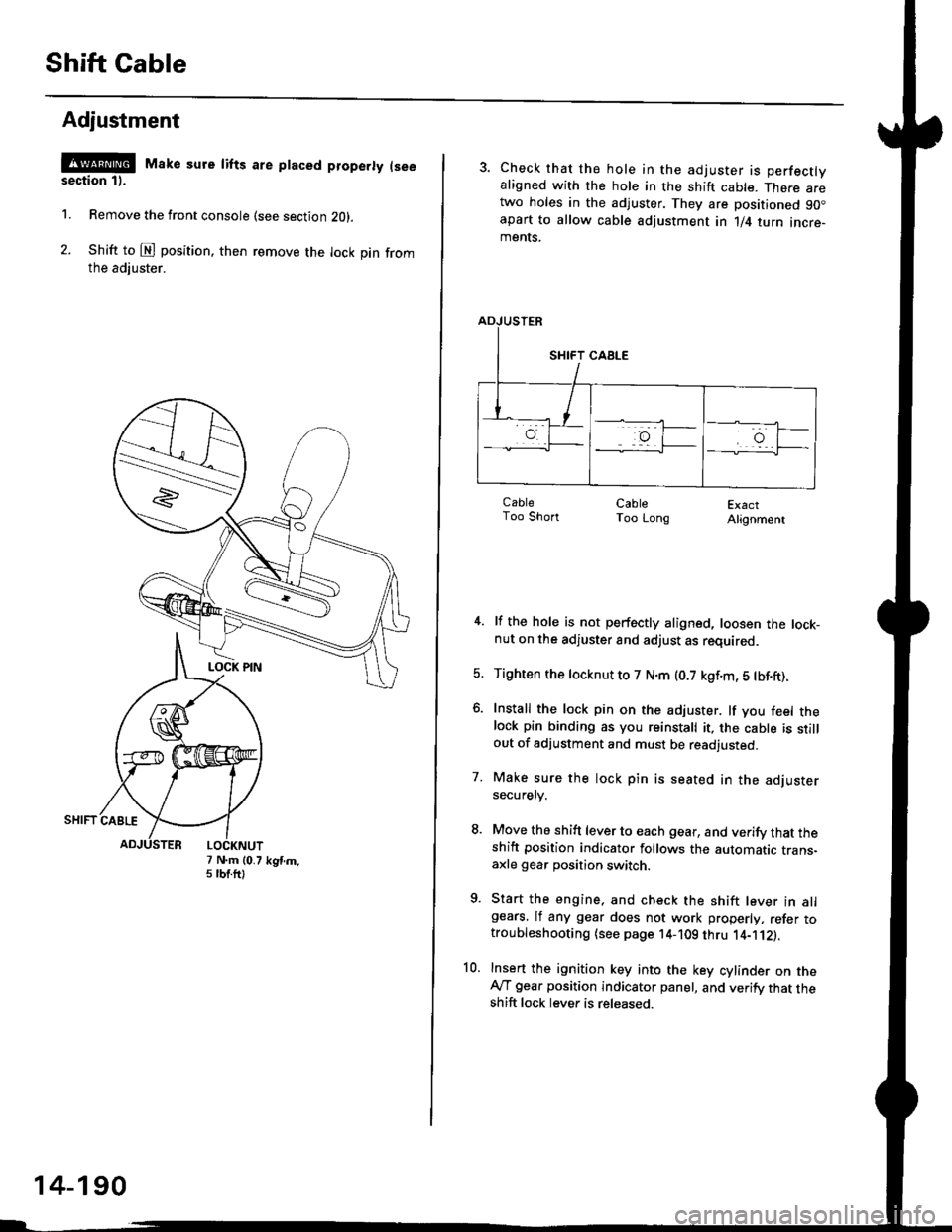
Adjustment
@ Make sure lifts are ptaced properly (see
section 1).
1. Remove the front console (see section Z0l.
2. Shift to @ position. then remove the lock pin fromthe adiuster.
7 N.m (0.75 tbtftlkgtm.
14-190
3. Check that the hole in the adjuster is perfectlyaligned with the hole in the shift cable. There aretwo holes in the adjuster. They are positioned 90.apart to allow cable adjustment in 1/4 turn incre-ments.
ExactAlignment
4. lf the hole is not perfectly aligned, loosen the lock-nut on the adjuster and adjust as required.
5. Tighten the tocknut to 7 N.m (0.7 kgf.m, 5 tbf.ft).
6. Install the lock pin on the adjuster. lf you feel thelock pin binding as you reinstall it, the cable is stillout of adjustment and must be readjusted.
7. Make sure the lock pin is seated in the adjustersecuretv.
8. Move the shift lever to each gear, and verify that theshift position indicator follows the automatic trans-axle gear position switch.
9. Start the engine, and check the shift lever in allgears. lf any gear does not work properly, refer totroubleshooting (see page 14-109 thru 1'4-'112).
10. Insert the ignition key into the key cylinder on theAy'T gear position indicator panel, and verify that theshift lock lever is released.
CableToo ShortCableToo Long
Page 869 of 2189
Shift Lever
PUSH KNOB SPRING
SILICONE GREASE
SCBEWN.m {0.3 kgtm.2 lbf ft)
Apply non-hardening thread lock sealant
SCREW3 N.m {0.3 kgif m,2 lblft)
GEAR POSITION INDICATOR PANEL
COVER
SHIFT LEVER ASSEMBLY
SHIFT INDICATOR
BUSHING
-61SILICONE GREASELEVERSHIFT LOCK
SCREW3 N.m {0.3
g
6x1.0mm9.8 N.m {1.0 kgf.m,7.2 tbt.ft)
A/T GEAR POSITION
PLATE
SHIFT LEVER BRACKET BASE
SHIFT LEVER
2/""*"
,.@* _.\__r.\
-Rt \ooru.r.,
A/T GEAR POSITION SWITCH
6x1.0mm9.8 N.m 11.0 kgf.m.7.2lbf.ft)
BASE COLLAA
14-191
Page 874 of 2189

Description
(cont'd)
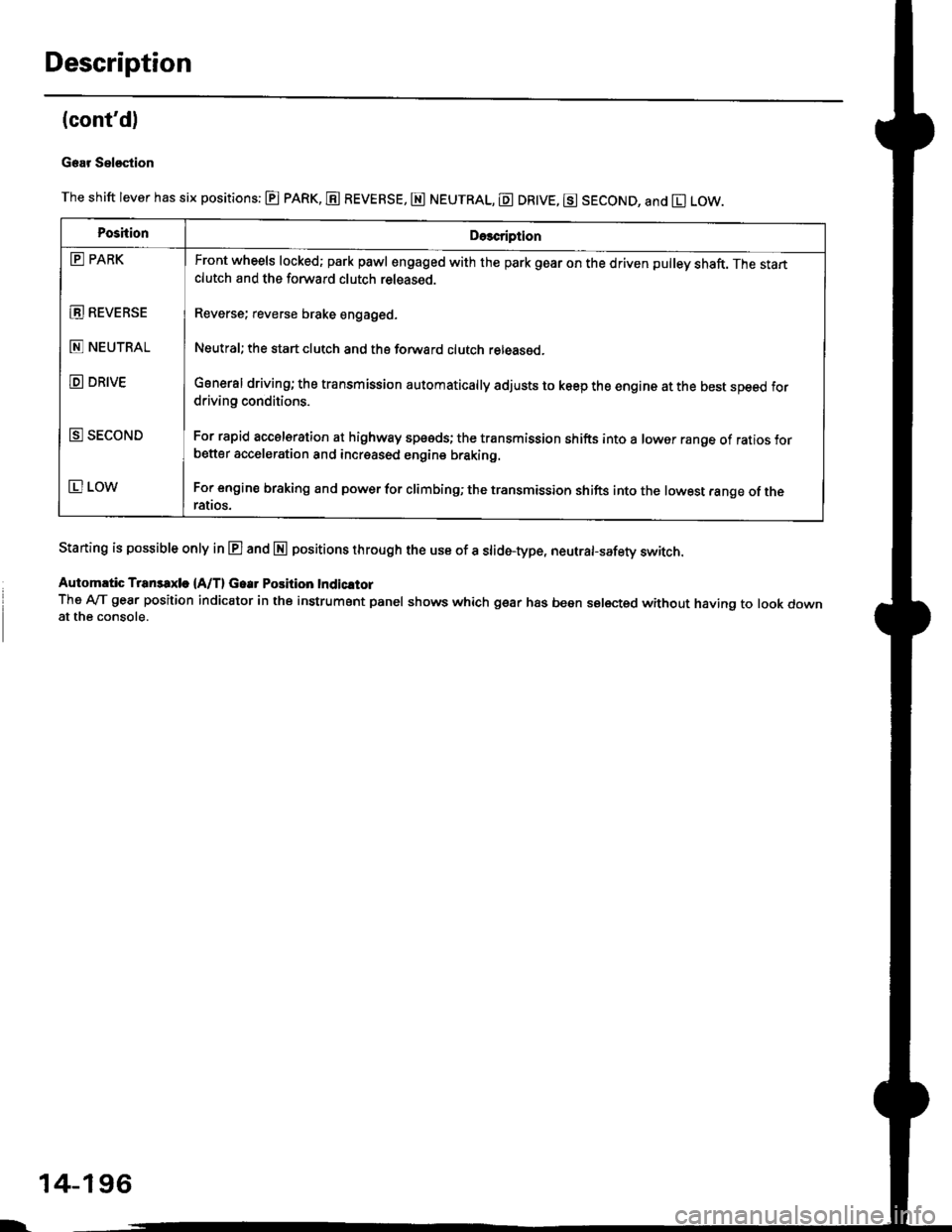
Gear Sel€stion
The shift lever has six positions: @ pARK, E REVERSE, E NEUTRAL, E DR|VE, g SECOND, and El LOW.
Staning is possible only in E and E positions through the use of a slid6-type, neutrafsafety switch.
Automrtic Transaxle {A/T} Gear Position Indicltor
The A-lT gear position indicator in the instrument panel shows which gear has been selected without having to look downat the console.
PoshionDe3cription
E PARK
E REVEBSE
E NEUTRAL
D DRIVE
E SECOND
E LOW
Front wheels locked; park pawl engaged with the park gear on the driven pulley shaft. The startclutch and the forward clutch released.
Reverse; reverse brake engaged.
Neutral; the start clutch and the forward clutch released.
General driving; the transmission automatically adjusts to keep the engine at the best speed fordriving conditions.
For rapid accelsration at highway speeds; the transmission shifts into a lower range of ratios forbetter acceleration and increased engine braking.
For engine braking and power for climbinO; the transmission shifts into the lowest range of theralros.
l-
14-196
Page 876 of 2189

Description
Clutches/Reverse Brake/Planetary Gear/Pulleys
Clulches/Reverse Brake
The CVT uses the hydraulically-actuated clutches and brake to engage or disengage the transmission gears. When
hydraulic pressure is introduced into the clutch drum and the reverse brake piston cavity, the clutch piston and the reverse
brake piston move. This presses the friction djscs and the steel plates together, locking them so they don't slip. Power is
then transmitted through the engaged clutch pack to its hub-mounted gear. and through engaged ring gear to pinion
gears.
Likewise, when the hydraulic pressure is bled from the clutch pack and the reverse brake piston cavity, the piston releases
the friction discs and the steel plates, and they are free to slide past each. This allows the gear to spin independently on its
shaft, transmitting no power.
Start Clutch
The start clutch, which is located at the end of the driven pulley shaft, engages/disengages the secondary drive gear.
The start clutch is supplied hydraulic pressure by its ATF feed pipes within the driven pulley shaft.
Forward Clutch
The forward clutch, which is located at the end of the drive pulley shaft, engages/disengages the sun gear.
The forward clutch is supplied hydraulic pressure by its ATF feed pipe within the drive pulley shaft.
Reverse Brake
The reverse brake, which is located inside the inte.mediate housing around the ring gear, locks the ring gear in E posi-
tion. The reverse brake discs are mounted to the ring gear and the reverse brake plates are mounted to the intermediate
housing. The reverse brake is supplied hydraulic pressure by a circuit connected to the internal hydraulic circuit.
Planetary Gear
The planetary gear consists of a sun gear, a carrier assembly, and a ring gear. The sun gear is connected to the input shaft
with splines. The pinion gears are mounted to the carrier which is mounted to the fo.ward clutch drum. The sun gear
inputs the engine power via the input shaft to the planetary gear, and the carrier outputs the engine power. The ring gear
is only used for switching the rotation direction of the pullev shafts,
In E. E, and E positions (forward range), the pinion gears don't rotate and revolve with the sun gear, so the carrier
rotates. In E] positjon {reverse range), the reverse brake locks the ring gear and the sun gear drives the pinion gears to
rotate. The pinion gears rotate and revolve in the opposite direction from the rotation direction of the sun gear, and the
carrier rotates with pinion gear revolution.
Pulleys
Each pulley consists of a movable face and a fixed face, and the effective pulley .atio changes with engine speed. The
drive pulley and the driven pulley are linked by the steel belt.
To achieve a low pulley ratio, high hydraulic pressure works on the movable face of the driven pulley and reduces the
effective diameter of the drive pulley. and a lower hydraulic pressure works on the movable face of the drive pulley to
eliminate the steel belt slippage. To achieve a high pulley ratio, high hydraulic pressure works on the movable face of the
drive pulley and reduces the eifective diameter of the driven pulley, and a lower hydraulic pressure works on the movable
face of the driven pulley to eliminate the steel belt slippage.
b
14-198
Page 878 of 2189
Description
Power Flow
E Position
. Start Clutch: released
. Forward Clutch: released
. Reverse Brake: released
Hydraulic pressure is not applied to the start clutch. forward clutch, and the reverse brake. Power is not transmitted to the
secondary drive gear.
E Position
. Start Clutch: released
. Forward Clutch: released
a Reverse Brake; released
Hydraulic pressure is not applied to the start clutch, forward clutch, and the reverse brake. Power is not transmitted to the
secondary drive gear. The secondary drive gear is locked by the park pawl interlocking the park gea..
FI-YWHEELFORWARD
INPUT SHAFT
SUN GEAR
START CLUTCHORIVEN PULLEY
FINAL ORIVEGEAR
PARK GEAR
FINAL DRIVEN GEAR
D
14-200
Page 895 of 2189
E position
The flow of fluid up to the drive pulley, the driven pulley' and the clutch reducing valve is the same as in E position The
pulley ratio is low b"car"" tt " o riu",i'prti"vi"""v"" t'igtr pressure.(pH) and the drive pulley receives low pressure {PL).
The manual valve is shifted into the B position, and it uncovers the port that leads reverse brake pressure (RVS) to the
reverse inhibitor valve. The inhibitoi Jenoid turns off by means of the TcM or PcM, and reverse inhibitor pressure (Rl) is
appliedtotherightendofthe,"u",""int,iui.o,u,|ve.Thereverseinhibitorva|vemovestothe|eftside,anduncoversthe
port that leads reverse brake pr"a"ur" tivst,o,he reverse brake. clutch reducing pressure (cR) becomes reverse brake
pressure (RVS) at the manuat *r"-, "nJ tro*" to the reverse brake. The reverse brake is engaged, and it locks the ring
gear.
NOTE: When used, "|eft" or "right" indicates direction on the hydraulic circuit'
(cont'd)
14-217
Page 899 of 2189
E] position, when the elestronic Gontrol system is faulty'
The flow of tluid up to the drive pulley, the driven pulley' and the start clutch is the same as in El position
The manual valve is shifted into the lE position' and it uncovers the port that leads reverse brake pressure {RVS} to the
reverse inhibitor valve. Reverse ,"nlu-i,"ip*r""i" (Rl) is applied to.the right end of the reverse inhibitor valve because of
afaultyinhibitorsolenoid.The'"t'",""inftiUito'valvemovestotheleftside'anduncoverstheportthatleadsreverse
brake pressure {RVS) to the ,"u"r." ir"t"- cru,ch reducing pressure (cR) becomes reverse brake pressure (RVS) at the
manual valve, and,lows to the ,e
"rs" lr"re. ttre reverse brake is engaged and locks the ring gear' This allows the vehi-
cle to drive in reverse.
NOTE: When used, "left" or "right" indicates direction on the hydraulic circuit'
14-221