Page 1805 of 2189
Airbag
)Replacement
After a collision in which the airbags were deployed' the
airbag assemblies and the SRS unit must be replaced'
!!!@ Store a removed airbag with the pad sur'
iFup. rr trt" airbag is improperly stored face down'
accidental deployment could propel the unit with
enough force to cause serious iniury'
CAUTION:
. Always disconnsct lhe airbag conn€ctor(s) when the
harness is disconnected.
. Do not disassemble or tamper with the ailbag'
NOTE:
. Do not install used SRS parts from another vehicle'
When repairing, use only new SRS parts'
o Carefully inspect the airbag before you install it Do
not insiall an airbag that shows signs oI being
dropped or improperly handled, such as dents' cracks
or deformation.
1. Disconnect the battery negative cable' then discon-
nect the positive cable from the battery' and wait at
least three minutes
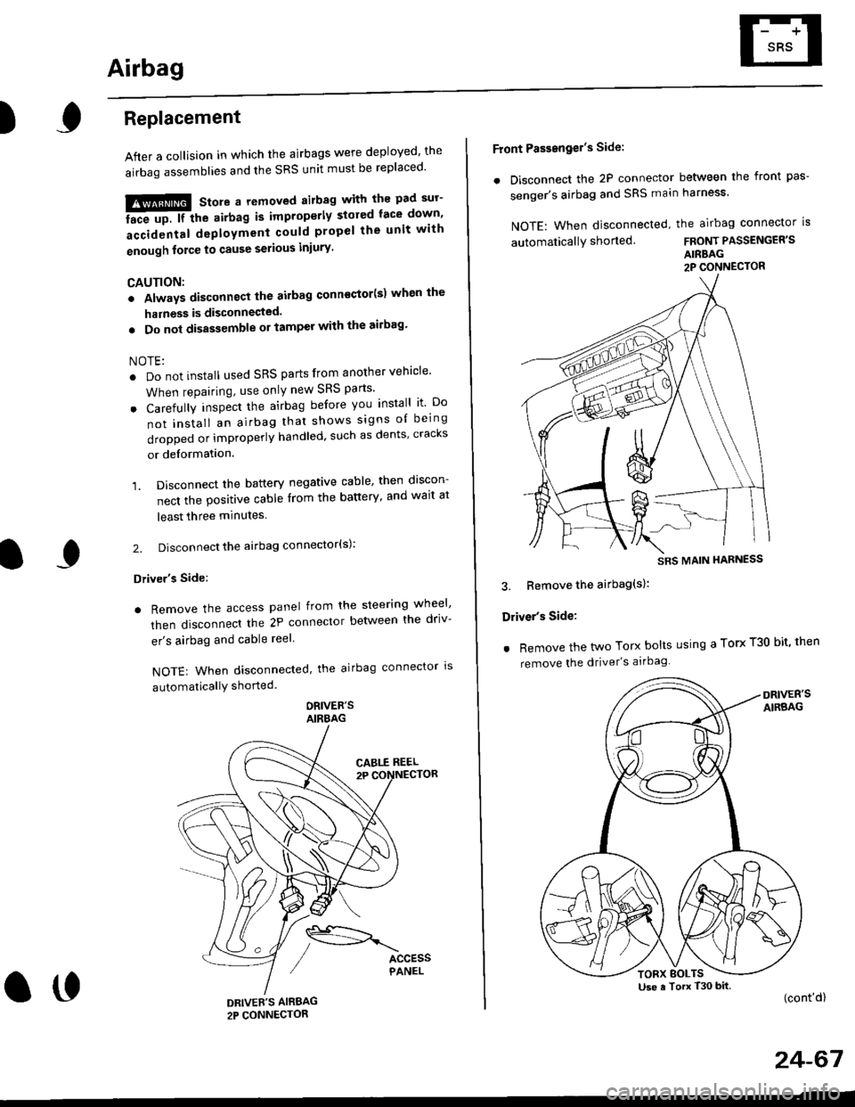
2. Disconnect the airbag connector(s):
Driver's Side:
. Remove the access panel from the steering wheel'
then disconnecl the 2P connector betlveen the driv-
er's airbag and cable reel
NOTE: When disconnected, the airbag connector ls
automaticallY shorted
ORIVER'SAIRBAG
DRIVEE'S AIRBAG2P CONNECTOR
oo
Front Passengel's Side:
. Disconnect the 2P connector between the front pas-
senger's airbag and SRS main harness'
NOTE: When disconnected, the airbag connector is
automaticallY shorted.FRONT PASSENGER'S
AIRBAG2P CONNECTOR
3. Bemove the airbag(s):
Driver's Side:
. Remove the two Torx bolts using a Torx T30 bit' then
remove the driver's airbag
(cont'd)
24-67
SRS MAIN HARNESS
Use a Torx T30 bitTORX BOLTS
Page 1808 of 2189
Airbag
Disposal
Before scrapping any airbags (including those in a wholevehicle to be scrapped), the airbags must be deployed. lfthe vehicle is still within the warranty period, before youdeploy the airbags, the Honda District Service Managermust give approval and/or special instructions. Onlv afterthe airbags have been deployed (as the result of vehiclecollision, for example), can they be scrapped.lf the airbags appear intact (not deployed). treat themwith extreme caution.
Follow this p.ocedure:
Deploying the Airbags: In.vehiclo
NOTE: lf an SRS vehicle is to be entirely scrapped, itsairbags should be deployed while still in the vehicle. Theairbags should not be considered as salvageable partsand should never be installed in another veh;cle.
!@ confirm thst oach airbag assembty issecurely mounted; otharwiso. sev€re personal iniurycould result lrom deployment.
1. Disconnect the baftery negative cable, then discon_nect the positive cable.
2. Confirm that the special tool is functioning properlyby following the check procedure on the tool labelor on page 24-'l'l .
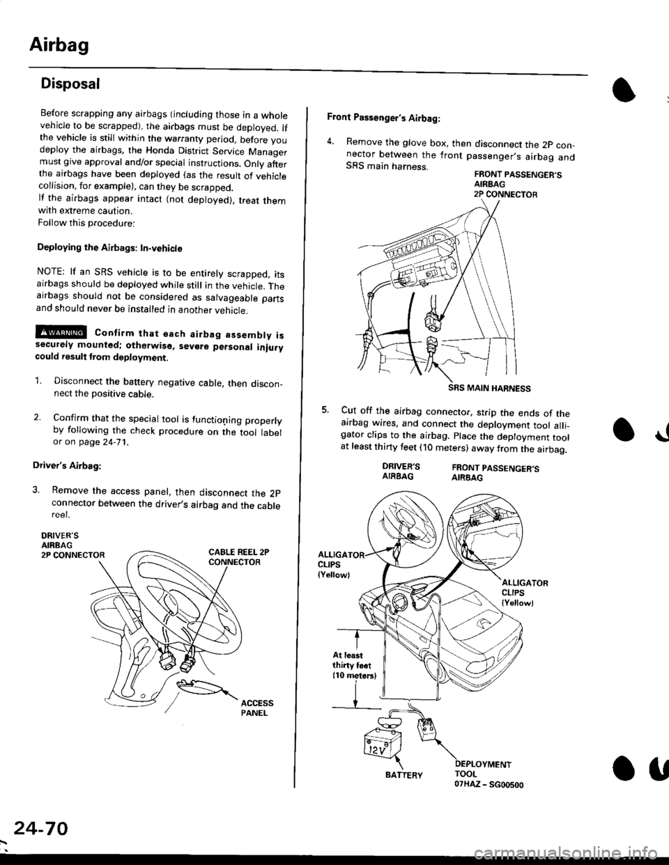
Driver's Airbag:
3. Remove the access panel, then disconnect the 2pconnector between the driver,s airbag and the cablereet.
DRIVER'SAIRBAG2P CONNECTOR
24-70
BATTERY.U
Front Passenger's Airbag:
4. Remove the glove box, then disconnect the 2p con-nector between the lront passenger,s airbag andSRS main harness.FRONT PASSENGER'SAIREAG2P CONNECTOB
SRS MAIN HARNESS
Cut off the airbag connector, strip the ends of theairbag wires, and connect the deployment tool alli_gator clips to the airbag. place the deployment toolat least thirty feet (10 meters) away from the airbag.
a!
DRIVER'SAIRBAGFRONT PASSENGER'SAIRBAG
ALLIGACLIPS(Yellow)ALLIGATORCLIPS{Yellowl
At loastthiny toet(10 metorsl
Page 1810 of 2189
Gable Reel
Replacement
!@@ store a .emove airbag assambly with thepad surtace up. lf the airbag is improperly stored face
down, accidental deploymont could propel the unit withenough force to cause sorious iniury.
CAUTION:
. Alwsys disconnect the airbag connoctor(s) when ih€harness is disconngcted.
. Do not disassemble or tamper with the airbag.
NOTE: Carefully inspect the airbag assembly beforeinstalling it. Do not install an airbag that shows signs ofbeing dropped or improperly handled. such as dents,cracks or deformation.
l.Disconnect the battery negative cable. then discon-nect the positive cable from the battery, and wait atleast three minutes.
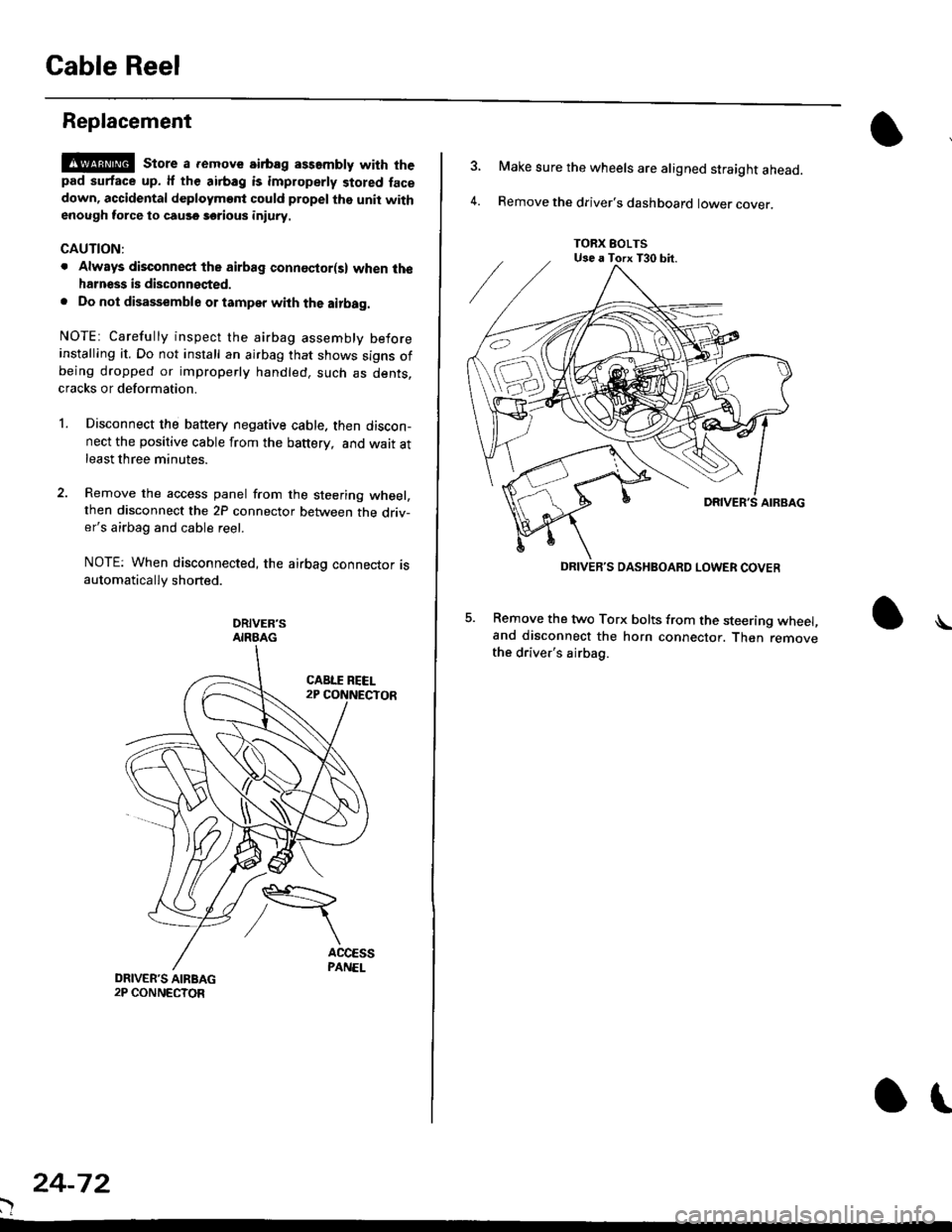
Remove the access panel from the steering wheel,then disconnect the 2P connector between the driv-er's airbag and cable reel.
NOTE: When disconnected, the airbag connector isautomatically shorted.
DRIVER'SAIRBAG
)
24-72
or
TORX EOLTSUse a Torx T30 bit.
DRIVEB'S DASHBOARD LOWER COVER
4.
Make sure the wheels are aligned straight ahead.
Remove the driver's dashboard lower cover.
5. Remove the two Torx bolts from the steering wheel,and disconnect the horn connector. Then removethe driver's airbag.
\
Page 1811 of 2189
\
6. Disconnect the connectors from the horn and cruise
control sevresume switches, then remove the steer-
ing wheel nut.
STEERINGNUT
CRUISE CONTROLSET/RESUMESWITCH CONNECTOR
)
HORN CONNECTOR
Remove the steerlng
pulrer.
CABLE REEL2P CONNECYOR
wheel using a steering wheel7.
STEERING WHEEL PULLEF
{Commerciallv_available)
)U
8. Remove the column covers.
Disconnect the 3P connector between the main wire
harness and cable reel sub-harness, 8nd the 2P con-
nector between the cable reel and SRS main harness'
CONNECTORHOLOER
SRS MAIN HARNESS2P CONNECTON
CABLE REEL SUBHARNESS3P CONNECTOR
10. Remove the cable reel from the column {cont'd}
24,73
--/
CABLE REEL
Page 1812 of 2189
Cable Reel
Replacement (cont'd)
11.
NOTE:
. Before installing the steering wheel, the front
wheels should be aligned straight ahead.. Be sure to install the harness wires so that theyare not pinched or interfering with other parts.. After reassembly. confirm that the wheels arestill turned straight ahead and that the steeringwheel spoke angle is correct (road test). lf minor
spoke angle adjustment is necessary, do so onlyby adjusting the tie-rods, not by removing andrepositioning the steering wheel.
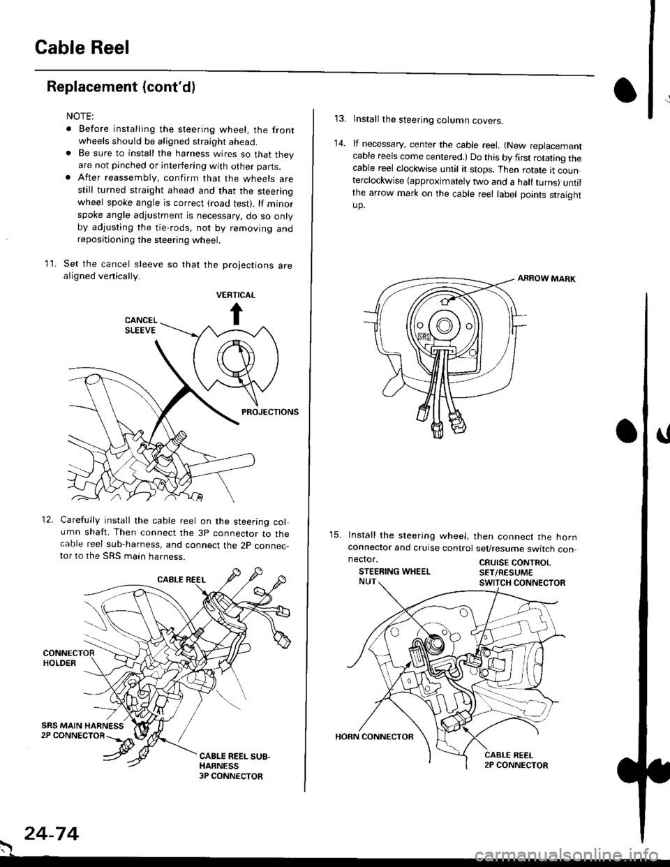
Set the cancel sleeve so that the projections arealigned venically.
PROJECTIONS
12. Carefully install the cable reel on the steering column shaft. Then connect the 3p connector to thecable reel sub-harness, and connect the 2p connec-tor to the SRS main harness.
. 24-74
Install the steering column covers.
lf necessary, center the cable reel. {New replacementcable reels come centered.) Do this by first rotating thecable reel clockwise until it stops. Then rotate tt counterclockwise (approximately two and a half turns) untilthe arrow mark on the cable reel label points straightup.
ARROW MARK
15. lnstall the sleering wheel, then connect the hornconneclor and cruise control sevresume switch con
14.
neclor.
STEERING WHEELCRUISE CONTROLSET/RESUM€
Page 1814 of 2189
SRS Unit
Replacement
CAUTION:
. Betore disconnoqting lny pErt of the SRS wire hal-ness, disconnect th9 airbag conn"ctorlsl.. During installltion or teplacemsnt. do not bump(impact w.cnch, hamm€r stc.l the area noar tho SRSunit.
NOTE:
o Do not damage the SRS unit terminals or connectors.. Do not disassemble the SRS unit; it has no service-able parts,
. Store the SRS unit in a clean, dry a.ea,. Do not use any SRS unit which has be€n subjected towater or shows signs of being dropped or improperlyhandled. such 8s dents, cracks or deformation.
1. Disconnect the bsttery negative cable. then discon-nect the positive cable from the battery, and wait atleast three minutes.
2. Disconnect the airbag connector{s}:
NOTE: When disconnected, the airbag connector isautomatically shorted,
Driver's Side:
. Remove the access panel from the steering wheel.then disconnect the 2P connector between the driv_er's airbag and cable reel (see page 24-11).
Front Passenge/s Side:. Disconnect the 2P connector between the tront oas_senger's airbag and SRS main harness (see page 24-11).
24-76
o\
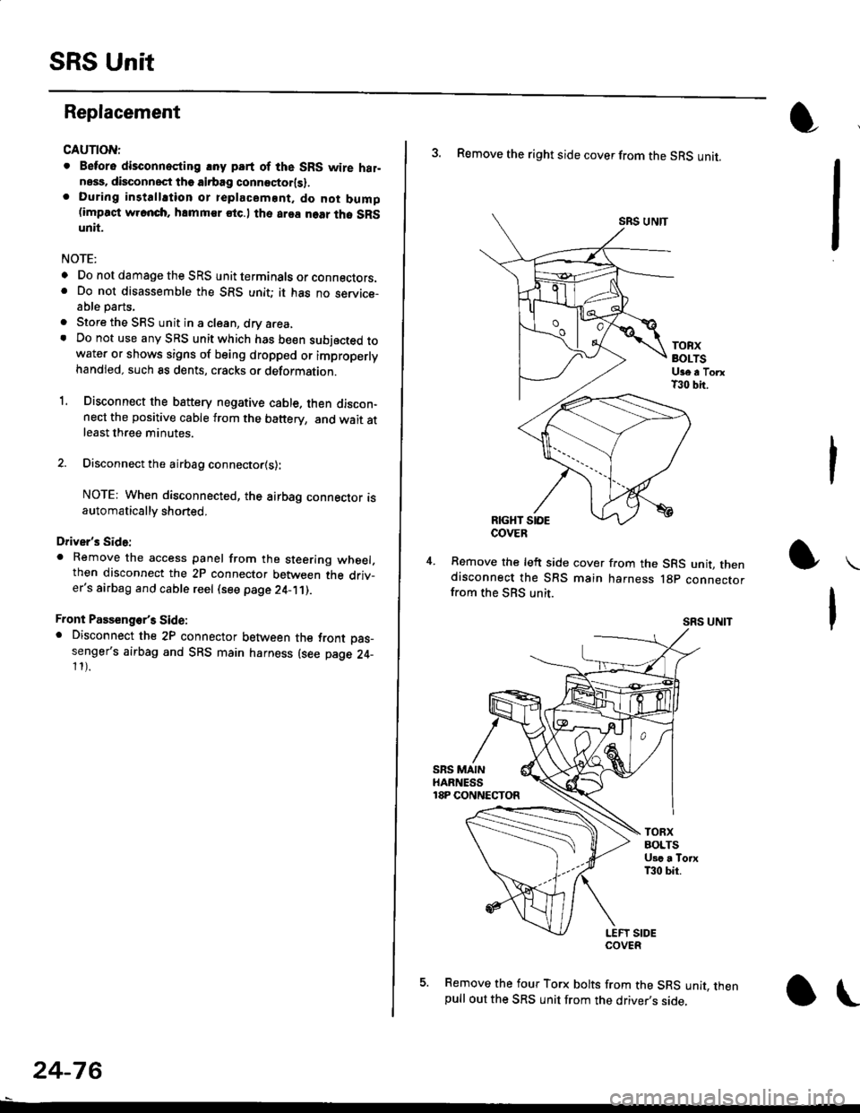
3. Remove the right side cover from the SRS unit.
SRS UNTT
TOBXBOLTSUge a TorxT30 bit.
RIGHT SIOE
Remove the left side cover from the SRS unit, thendisconnect the SRS main harness lgp connectorfrom the SBS unit.
SRS UNIT
5. Remove the four Torx bolts from the SRS unit, thenpull out the SRS unit from the driver,s side,
COVER
Page 1815 of 2189
6. Install the new SRS unit.
NOTE: Do not reuse a torx bolt that has red
threads. Replace the bolt with a new one.
)
7.
TORX BOLTS9.8 N.m l'1.0 kg{.m, 7.2 lbf.ft}Use a Torx T30 bit.
Connect the SRS main harness l8P connector to the
SRS uniu push it into posjtion until it clicks.
Install the SRS unit covers (ri9ht and left). Make
sure the covers snap together in the middle.
8.
TORX BOLTS9.8 N.m 11.0 kgf.m, 7.2 lbf.ft)U3e . Torx T30 bit.
SRS MAIN HARNESS
)(l
9.
10.
't2.
Reconnect the driver's aibag 2P connector to the
cable reel 2P connector, then reinstall the access
panel on the steering wheel.
Reconnect the tront passenger's airbag connector
to the SRS main harness.
Reconnect the battery positive cable, then the nega
tive cable.
After installing the SRS unit, confirm proper system
operation: Turn the ignition switch ON (ll); the SRS
indicator light should come on for about six seconds
and then go oif.
11.
24-77
.-
Page 1823 of 2189
How To Use This Manual
Component Locations
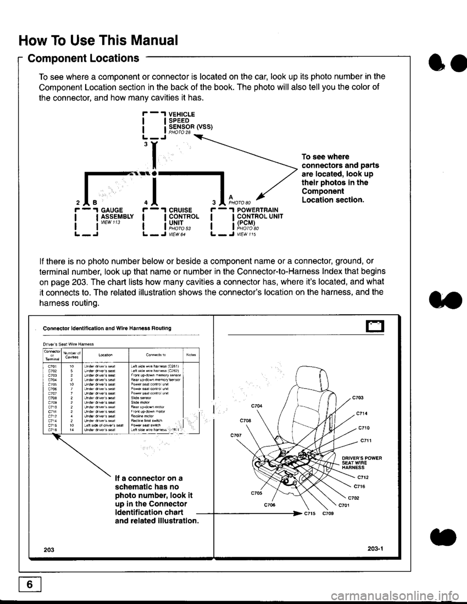
To see where a component or connector is located on the car, look up its photo number in the
Component Location section in the back of the book. The photo will also tell you the color of
the connector, and how many cavities it has.
To see where
connectors and parts
are located, look up
their photos in the
Component
Location section.
I
I
3
r - 1 GAUGE
| | I_S-9_EIBLY
lt''""'
r - 1 cRUtsE
! !fi':*
r - 1 POWERTRAIN
I I CONTROL UNrr
a i[i9#r,
lf there is no photo number below or beside a component name or a connector, ground, or
terminal number, look up that name or number in the Connector-to-Harness Index that begins
on page 203. The chart lists how many cavities a connector has, where it's located, and what
it connects to. The related illustration shows the connector's location on the harness, and the
harness routing.
Connactor ldontlticallon and Wke Harness Rouling
DFIVEF'S POWERSEAT WIAEHAFNESS
It a connector on a
schematic has no
photo number, look it
up in the Connector
ldentilication chart
c712
c7t6
c702c701
and related illustration.
203203.1
Drlvor s Sea! wne Harn€ss
Lefts'd.Hrc hatu$ 1c2611Loft s'd. src hamass 1c262)
F6ar up.dow^ n.morykisor
l
E
oo