Page 562 of 2189
I
\
\l
(From page 11-292i
Chock the tollowing parts tolleakage to aimosphero, and
ropaii or replaco if necess6.y:. fuel fill cap. fuel tank. fuel v.por pipe. EVAP two way valve. EVAP bypas solonoid valve. tuel tank pre3suae sen3or. EVAP control cankter. EVAP control canisier veni3hut valve. EVAP purge conttol solenoid
. ORVR vent 3hut valve. ORVB vaoor recirculation valve. vacuum hoses tnd connactions
(From page 11 292)
Check toi an opon in the wiro(2wBS linol:1. Turn the ignition switch OFF.2. Reconnect the 2P connectorto the EVAP bypass solenoid
3. Turn the ignition switch ON (ll).
4. Measure voltage betweenECM/PCM connector terminals43 and 82.
Reprir opan in tho wire be(wean
th. EVAP byp.is solonoid valve
rnd rhe EcM/PcM (A31.ls there baftery voltage?
(cont'd)
11-293
Page 585 of 2189

Transmission Assembly
I
Removal
@. Make sure iacks and safety stands are placed prop€dy,
and hoist brackets are atlach€d to correct position on
the enginc.
. Apply parking brake and block rear whosls so car will
nol roll olf stands and lall on you while working under
it.
CAUTION: Use fender covers to svoid damaging painted
surfaces.
1. Disconnect the negative {-) cable first, then the pos-
itive (+) cable from the battery'
Drain transmission oil {see page 13-3).
Remove the intake air tube. intake air duct and air
cleaner housing assembly (see section 5).
Disconnect the starter motor cables, transmission
ground wire and back-up light switch connector.
6x1.0 mm BACK-UP LIGHT
9.8 N.m (1.0 ksf.m, 7.2 lbI.ft) swlTcH CoNNECTOR
8x 1 .25 mm8.8 N.m {0.9 kgt.m,6.5 lbf.ftl
\
ARTER
5. Remove the wire harness clamps.
vssCONNECTOR
6. Disconnect the vehicle speed sensor (VSS) connec-
ror.
Remove the clutch line bracket, clutch line clamp,
and slave cvlinder.
CAUTION:
. Do not opsr.te tho clutdh pedal once the 3lavc
cylindor has b6on romoved.
. Tske care not to bend tha clutch lin6.
7.
(cont'd)
13-5
Page 628 of 2189

Transmission Assembly
l
,
{
Removal
@Make sure iacks and safoty stands are placad plop-
erly (3ee section l).
Apply parking braks and block rear wheels so car
will not roll off stands and fall on you while working
under il.
CAUTION: Us6 fonder cove6 to avoid damaging painted
sudaces.
Disconnect the negative (-) cable from the battery,
then the positive (+l cable.
Drain the transmission oil. then reinstall the drain
plug with a new washer (see page 13-47).
Remove the intake air duct and the air cleaner hous-
ing assembly (see s€ction 5).
Disconnect the back-up light switch connector and
the transmission ground wire.
Remove the lower radiator hose clamp from the
transmission hanger B.
L
8 x 1 .25 mm22Nm12.2kgl'm�,
LOWER RADIATORHOSE CLAMP
16 rbtft)
13-48
7.
Bemove the wire harness clamps.
Disconnect the starter motor cables and the vehicle
speed sensor (VSS) connector.
8 x 1.25 mm8.8 N.m (0.9 kgf.m,6.5 tbtftl
STARTERMOTORCABLES
8. Remove the clutch line bracket and the slav6 cylin-
oer.
NOTE: Do not operate the clutch pedal once the
slave cylinder has been removed.
\J
Page 728 of 2189
Troubleshooting Procedures
1.
2.
(cont'dl
Remove the kick panel on the passenger's side {see section 20}.
Remove the PCM. and turn the PCM over.
Inspect the circuit on the PCM according to the troubleshooting flowchart with the spocial tools and a digital multime-ter as shown.
How lo Use tha Backprobe Set
Connect the backprobe adapters to the stacking patch cords, and connect the cords to a multimeter. Using the wireinsulation as a guide for the contoured tip of the backprobe adapter, gently slide the tip into the connector from thewire side until it comes in contact with the terminal end ofthe wire.
BACKPROSE
BACKPROBE SET07saz - (xtl(xtoA
{two required)
DIGITAL MULNMEIER(Comm€rcially 6vailabl€l-aHM-32-003
t..
14-50
or equival€nt
Page 734 of 2189

Electrical Troubleshooting (,96 - gg Models)
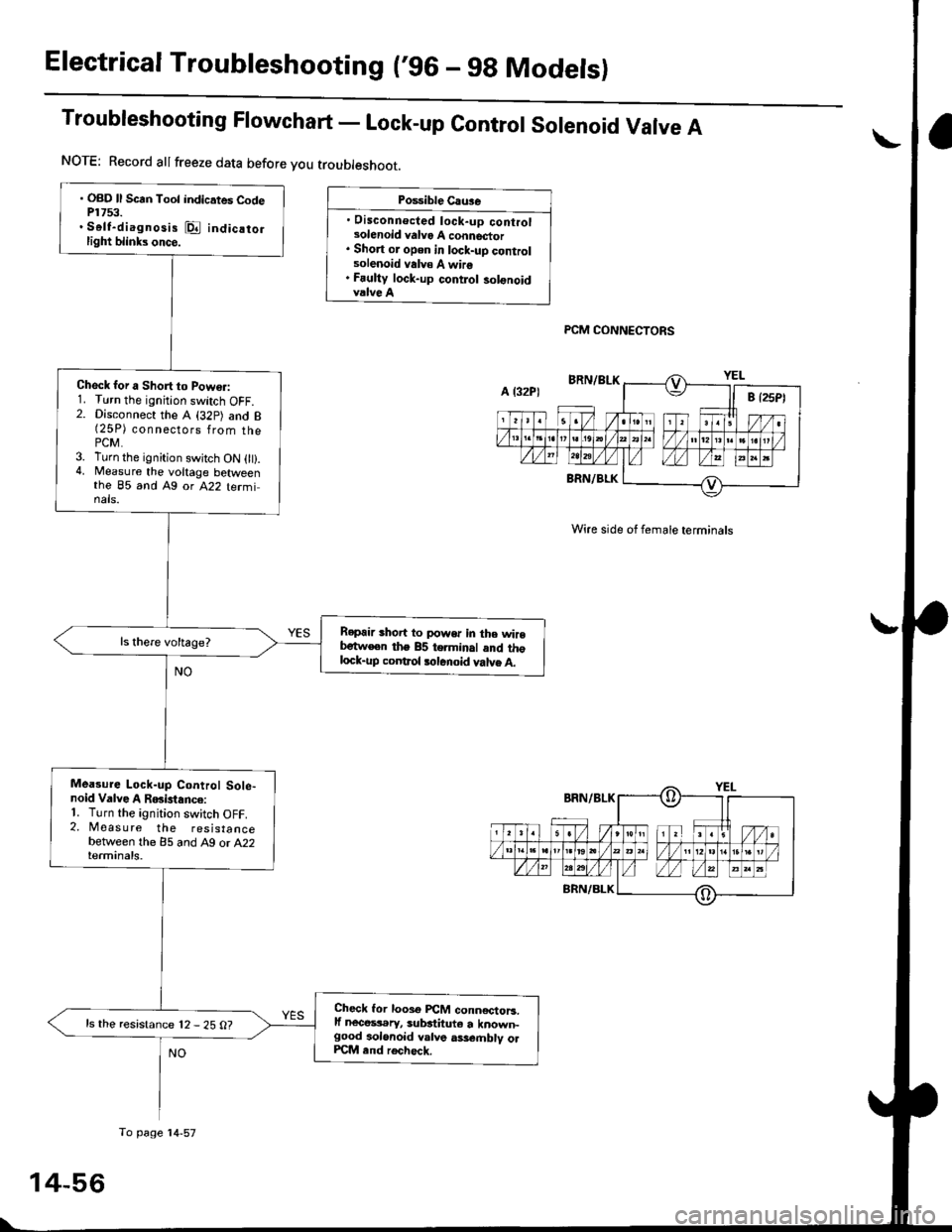
Troubleshooting Flowchart - Lock-up contror sorenoid Varve A
Po$ible Cau3e
. Disconnecled lock-up controlsolenoid valvo A connector. Short or open in lock-uD controlsolenoid valv€ A wire. Fauliy lock-up contlol solonoidvalve A
PCM CONNECTORS
Wire side of female terminals
. OBD ll Scrn Toot indicates CodeP1753.. Self-diagnosis @ indicatorlight blinks once.
Check for a Short to Powo.:1. Turn the ignition switch OFF.2. Disconnect the A (32p) and B(25P) connsgl6ps 1rq- thaPCM.3. Turn the ignition swjtch ON 0t).4, Measure the voltage betweenthe 85 and Ag or A22 terminals.
Repair shoit to power in the wirebetw€en the 85 terminal and thglock-up coDtrol tolenoid valve A.
Mea3ure Lock-up Control Sole-noid Valve A RGislance:'1. Turn the ignition switch OFF.2. Measure the resistancebetween the 85 and A9 or A22terminals.
Check lor looso PCM conn€ctoB.lf nece$.ry, substituto a known-good aolonoid valve ass€.nblv olPCM end rech6ck.
ls the resistance 12 - 25 O?
NOTE: Record allfreeze data before you troubleshoot.
A l32P)
To page'14-57
Page 735 of 2189
From page 14-56
Ch6ck Lock-up Control Solenoid
Valve A tor a Short Cilcuiti
1. Disconnect the 2P connector
lrom the lock-up control sole-
noid valve assemblY.2. Check for continuity between
the 85 and Ag or A22 termi-
nats.
Ropair 3hort to giound in iha wila
b.twoqn th6 85 terminrl rnd tho
locl-up control 3olanoid valvo A.
Mo..ura Lock-up Control Sole'
noid Velve A Reri3tanc. at tho
Solenoid Conn6cto.:Measure the resistance betweenthe No. 2 terminal of the lock-up
control solenoid connector and
body ground.
Chock for opan in tha wit.
ba(w.an tha 85 torminll lnd the
lock-uo control lolanoid vtlYa A.ls the resistance 12 _ 25 O?
Roplsce tho lock"up cont.ol 3ol€_
noid vllvo arsembly.
PCM CONNECIOBS
Wire side of lem6leterminals
LOCK.UP CONTROLSOrINOID CONNECTOR
YEL
Teaminal side of malo terminals
lml-,f
(o)
I
14-57
Page 736 of 2189

Electrical Troubleshooting ('96 - 9g Modelsl
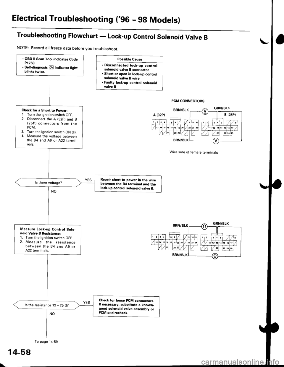
Troubleshooting Ftowchart - Lock-up control sorenoid Varve B
Possible Cause
. Disconnected lock-up controlsolenoid valve B connector' Short or open in lock-up controlsolonoid valve B whe. Faulty lock-up control solenoidvalve B
PCM CONNECTORS
Wire side of female terminals
. OBD ll Scan Tool indicrtes CodeP1758.. Self-diagnosis E indicrtor lightblinkstwice.
Check for a Shon to Power:1. Turn the ignition switch OFF.2. Disconnect the A (32p) and B(25P) connectors from thePCM,3. Turn the ignition switch ON t).4. Measure the voltage betweenthe 84 and A9 or A22 termi-nals.
Repeir short to power in the wirebetween the 84 teiminal and thelock-up control solenoid valve B.
Moasure Lock-up Control Sole-noid Valve B Resistance:1. Turn the ignition switch OFF.2. Measure the resistancebetween the 84 and Ag orA22 terminals.
Check for loose FCM connectors,lf necessary, substitute a known-good solenoid valve assembly olP1CM and rech6ck.
ls the resistance 12 - 25 O?
NOTE: Record all freeze data before you troubleshoot.
A {32P)
To page 14-59
t-
Page 737 of 2189
From page 14 58
Check Lock-up Control Solenoid
Valve B for a Short Circuh:
1. Disconnect the 2P connector
from the lock-uP control sole'
noid valve assefibly.
2. Check for continuity between
the 84 and A9 or A22 terma-
nals,
Rgprir 3hort to ground in tho wite
Hwoon the 84 torminal and the
lock-uo contlol solonoid valvs B.ls there continuity?
Measu.o Lock-uP Control Sole'
noid Valve I Resistance at tho
Solenoid Connector:Measure the resistance between
the No. 1 terminal o{ the lock-up
control solenoid connector and
body ground.
Chcck tor opcn in the wirs
b€tlve.n the 84 ierminal and tho
lock-up conttol solonoid vllvc B.ls the resistance 12 - 25 O?
Reolace the lock'up control sole-
noid valve assemblY.
PCM CONNECTORS
Wire side oI lemale terminals
LOCK.UP CONTROL
SOLENOID CONNECTOR
IFl;II-r:-]
6nn/eLKfi
I
Terminal sido ot male terminals
14-59