1999 HONDA CIVIC warning
[x] Cancel search: warningPage 1206 of 2189
e\
t
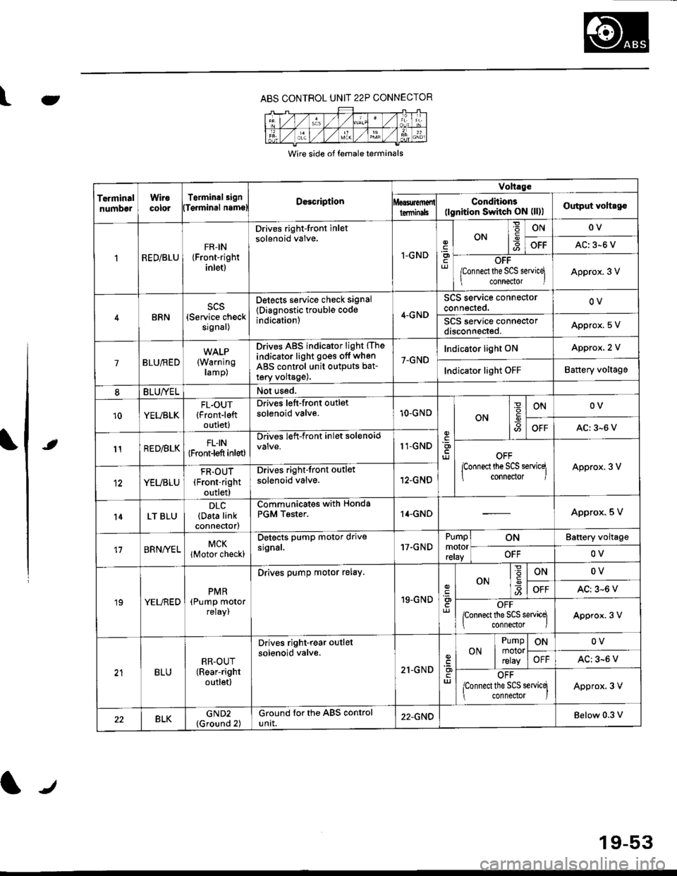
ABS CONTROL UNIT 22P CONNECTOR
Wire side of female terminals
TerminalnumbelWirocororTerminalsignDe3cription
Volt.ge
ConditionE(lgnition Switch ON (ll)lOutput voltagolTqrminal namslterminils
RED/BLUFR-IN{Front-rightinlet)
Drives right-front inletsolenoid valve.
I-GNDriJ
ON-9ONOV
OFFAC: 3-6 V
OFF
/Connect the SCS servicq
connector IApprox. 3 V
BRNscs(Service checksignal)
Detects service check signal
{Diagnostic trouble codeindication)4-GND
SCS service connectorconnected.OV
SCS service connectordisconneded.Appro)(. 5 V
7BLU/RED(Warning
ramp)
Drives ABS indicator light (The
indicator light go€s off when
ABS control unit outputs bat-
tery volta9e),
7-GND
Indicator light ONApprox, 2 V
Indicator light OFFBattery voltage
8BLU/YELNot used.
10YEUBLKFL.OUT{Front-leftoutlet)
Drives left-front outletsolenoid valve.10-GNOON
ONOV
OFFAC:3-6 V
11RED/BLKFLIN{Front-l€ft inlet)
Drives left-front inlet solenoid11-GNDOFF
lconnect the SCS servicq
connector IApprox. 3 V
YEUBLU
FR.OUT(Front-right
outlet)
Drives right-front outlet
solenoid valve.12-GNO
l4LT BLUDLC(Data linkconnector)
Communicates withPGM Tester.Honda14.GNDApprox. 5 V
17BRNA/ELMCK
lMotor check)
Detects pump motor drivesrgnal.17.GNDPumpmotorreray
ONBattery voltage
OFFOV
19YELREDPMR(Pump motorreray,
Drives pump motor relay.
19-GND
ONONOV
OFFAC: 3-6 V
OFFponnect the SCS sewicq
connedor lApprox. 3 V
BLURR-OUT(Rear-right
outletl
Drives right-rear outlel
solenoid valve.
21-GNDuJ
ON
Pumpmotorrelay
ONOV
OFFAC: 3-6 V
OFF
lconnect the SCS servicq
connedor )Approx. 3 V
22BLKGND2(Ground 2)Ground for the ABS controluntt.22-GNDBelow 0.3 v
19-53
Page 1207 of 2189
Troubleshooting Precautions
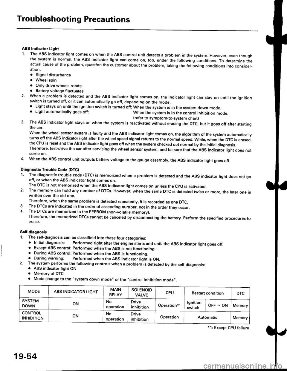
ABS Indicator Light
I The ABS indicator light comes on when the ABS control unit detects a problem in the system. However, even thoughthe system is normal, the ABs indicator light can come on, too, under the following conditions. To determine theactual cause of the problem, question the customer about the problem, taking the following conditions into consider-ation.
. Signal disturbance
. Wheel soin
. Only drive wheels rotate. Battery voltage fluctuates
2. When a problem is detected and the ABS indicator light comes on, the indicator light can stay on untat the ignitionswitch is turned off, or it can automatically go off, depending on the mode.. Lightstayson until the ignition switch isturned off;When the system is inthesvstem down mode.o Light automatically goes off:When the system is in the control inhibition mode.(refer to symptom-to-system chart)3 The ABS indicator light stays on when the system is reactivated without erasing the DTC, but it goes off after startingthe car.
when the wheel sensor system is faulty and the ABS indicator light comes on, the algorithm of the system automaticallyturns off the ABS indicator light after the wheel speed signal returns to the normal speed. while, when the DTC is erased,the CPU is reset and the ABS indicator light goes off when the system check€d out normal by the initial diagnosis.Therefore, test-drive the car after servicing the wheel sensor system, and be sure that the ABS indicator light does notcome on.
4. When the ABS control unit outputs battery voltage to the gauge assembty, the ABS indicator light goes off.
Diagnostic Trouble Code (DTC)
1. The diagnostic trouble code (DTC) is memorized when a problem is detected and the ABS indicator light does not gooff, or when the ABS indicator light comes on.The DTC is not memorized when the ABs indicator right comes on unress the cpU is activated.2. The memory can hold any number of DTCs. However, when the same DTc is detected twice or more, the later one iswritten over the old one.
Therefore. when the same problem is detected repeatedly, it is recorded as one DTC.3. The DTCS are indicated in the order of ascending number, not in the order thev occur.4. The DTCS are memorized in the EEpROM {non-volatile memorv}.Therefore, the memorized DTCS cannot be canceled by disconnecting the battery. perform the specified orocedures toerase.
Solf-diagnosis
1. The self-diagnosis can be classifield into these four categories:' Initial diagnosis; Performed right after the engine sta rts and untiltheABs indicator light goes off.o Except ABS control: Performed when the ABS is not functioning,. During ABS control: Performed when the ABS is functioning.. During warning: Performed when the ABS indicator light is ON.2 The system performs the following controls when a problem is detected by the self-diagnosis:. ABS indicator light ON. Memory of DTC
. Mode change to the "system down mode,, or the "control inhibition mode,,.
MODEABS INDICATOR LIGHTMAIN
RELAY
SOLENOID
VALVECPURestart conditionDTC
SYSTEM
DOWNONNo
operal|on
Drive
inhibitionOperation+rlgnition
switchOFF - ONMemory
CONTROL
INHIBITIONONNo
operat|on
Orive
inhibitionOperationAutomaticMemory
*1: Except CPU failure
19-54
Page 1300 of 2189
Dashboard
Gomponent Removal/lnstallation
(cont'd)
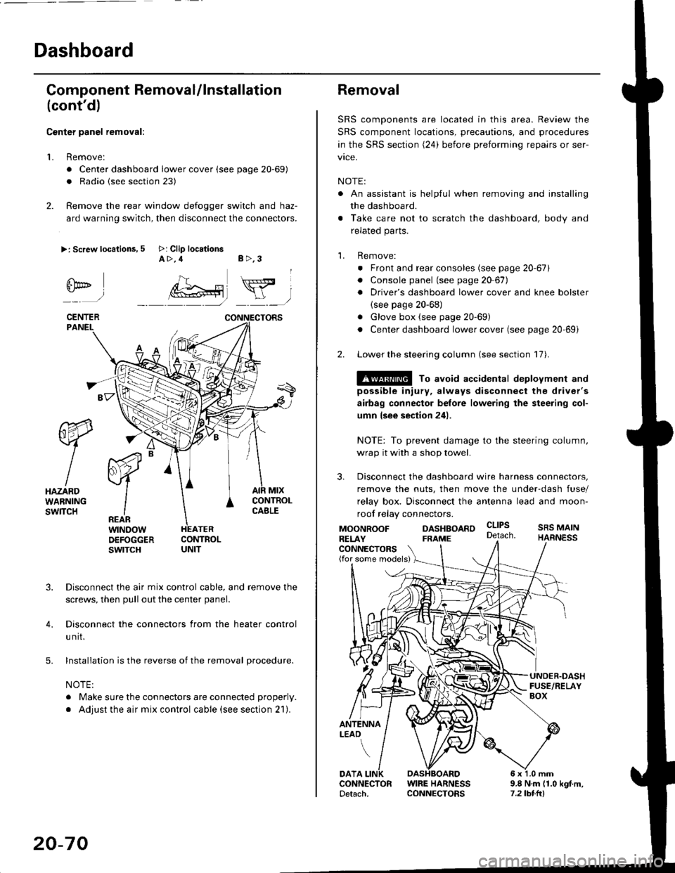
Center panel removal:
1. Remove:
. Center dashboard lower cover (see page 20-69)
. Radio {see section 23)
2. Remove the rear window defogger switch and haz-
ard warning switch, then disconnect the connectors.
>: Screw locations, 5 >: Clip locationsA>,4 B>,3
fii*-)
CENTERPANEI.
rt-xR.
W
IHAZARDWARNINGswlTcH
r44 "
F.IZvl
IIREARwtNoowOEFOGGERswtrcH
MtxCONTNOLCABLE
3. Disconnect the air mix control cable, and remove the
screws, then pull out the center panel.
4. Disconnect the connectors from the heater control
u nit.
5. Installation is the reverse of the removal procedure.
NOTE:
. Make sure the connectors are connected properly.
. Adjust the air mix control cable (see section 21).
20-70
Removal
SRS components are located in this area. Review the
SRS component locations, precautions, and procedures
in the SRS section (24) before preforming repairs or ser-
vice.
NOTE:
. An assistant is helpful when removing and installing
the dashboard.
. Take care not to scratch the dashboard, body and
related parts.
1. Remove:
o Front and rear consoles (see page 20-67)
. Console panel (see page 2O 67),
. Driver's dashboard lower cover and knee bolster(see page 20-68)
. Glove box (see page 20-69)
. Center dashboard lower cover (see page 20-69i
2. Lower the steering column (see section 17).
@ To avoid accidental deplovment and
possible injury, always disconnect the driver's
airbag connector belore lowering the steering col-
umn lsee section 241.
NOTE: To prevent damage to the steering column,
wrap it with a shop towel.
3. Disconnect the dashboard wire harness connectors,
remove the nuts, then move the under-dash fuse/
relay box. Disconnect the antenna lead and moon-
roof relay connectors.
DASHBOARD cltPs
CONNECTORS(for some models)
MOONROOFRELAY
ANTENNALEAO
FRAME
SRS MAINHARNESS
9.8 N.m (1.0 kgf m,7.2lbt.ltl
DATACONNECTOR WIRE HARNESSDetach. CONNECTORS
Page 1365 of 2189
DashboardBumpers
I
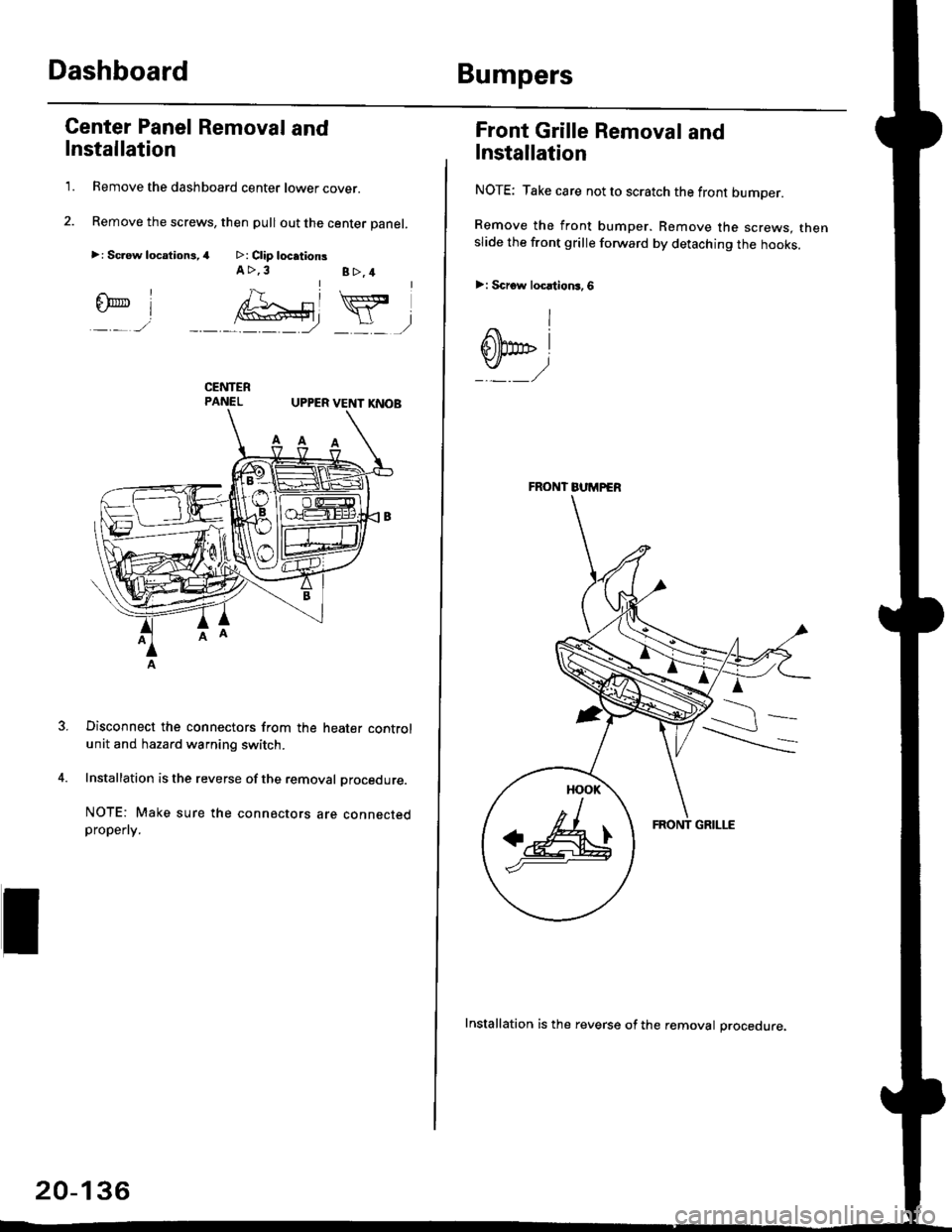
Center Panel Removal and
Installation
1. Remove the dashboard center lower cover.
2. Remove the screws, then pull out the center panel.
>: Sc.ew locationi,4 >: Clip locationsA >,3B>,4rl
@Y,
UPPER VENT I(NOB
Disconnect the connectors from the heater controlunit and hazard warning switch.
Installation is the reverse of the removal procedure.
NOTE: Make sure the connectors are connectedpropefly.
20-136
Installation is the reverse of the removal procedure.
FRONT BUMPER
a&
Front Grille Removal and
Installation
NOTE: Take care not to scratch the front bumper.
Remove the front bumper. Remove the screws. thenslide the front grille forward by detaching the hooks.
>: Scrow locltion3,6
I
dbp i
Page 1416 of 2189
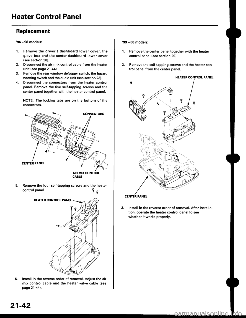
Heater Control Panel
'95 - 98 modolsi
Remove the driver's dashboard lower cover, the
glove box and the center dashboard lower cover(see section 20).
Disconnect the air mix control cabls from the heater
unit {see page 21-44).
Remove the rear window defogger switch, the hazard
warning switch and the audio unit (see section 23).
Disconnect the connectors from the heater control
panel. Remove the five self-tapping screws and the
center panel together with the heater control panel.
NOTE: The locking tabs are on the bottom of the
connecrors.
Install in the .everse order of removal. Adjust the air
mix control cable and the heater valve cable {seepage 21-44)..
Replacement
1.
Remove the four self-tapping screws and the heater
21-42
1.
'9!, - 00 modols:
Remove the center panel together with the heater
control panel (see section 20).
Remove the self-tapping screws and the heater con-
trol panelfrom the center Danel.
Install in the reverse order of removal. After
tion, operate the heater control panel to see
whether it works properly.
installa-
Page 1509 of 2189
D
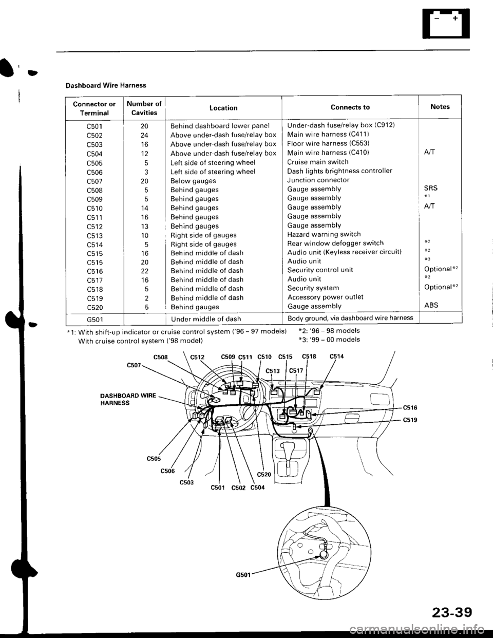
Dashboard Wire Harness
Connector ol
Terminal
Numbel of
CavitiesLocationConnects toNotes
c501
c502
c503
c504
c505
c507
c508
c509
c510
c513
c514
c515
c516
c518
c519
c520
20
24
to
12
5
3
20
5
5
14
r0
5
20
22
5
2
5
Behind dashboard lower panel
Above under-dash luse/relay box
Above under dash Iuse/relay box
Above under dash tuse/relay box
Left side of steering wheel
Left side of steering wheel
Below gauges
Behind gauges
Behind gauges
Behind gauges
Behind gauges
Behind gauges
Right side ot gauges
Right side oI gauges
Beh ind middle of dash
Behind middle of dash
Behind middle of dash
Behind middle of dash
Behind middle of dash
Behind middle of dash
Behind gauges
Under-dash {use/relay box (C912)
Main wire harness 1C411)
Floor wire harness (C553)
Main wire harness (C410)
Cruise main switch
Dash lights brightness controller
Junction connector
Gauge assembly
Gauge assembly
Gauge assembly
Gauge assembly
Gauge assembly
Hazard warning switch
Rear window defogger switch
Audio unit (Keyless receiver circuit)
Audio unit
Security control unit
Audio unit
Security system
Accessory power outlet
Gauge assembly
A"r
SRS
A,/r
Optio nal*'�
Option al*'�
ABS
G501Under middle ol dashBody ground, via dashboard wire harness
*1: With shiit-up indicator or cruise control system ('96 - 97 models)
With cruise control system ('98 model)
c509 C511 c510 c515
13 lc5l7
*2: '96 98 models*3: '99 - 00 models
c508
DASHSOARD WIREHARNESS
c501
c520
c502 c504
23-39
Page 1533 of 2189
(l'-
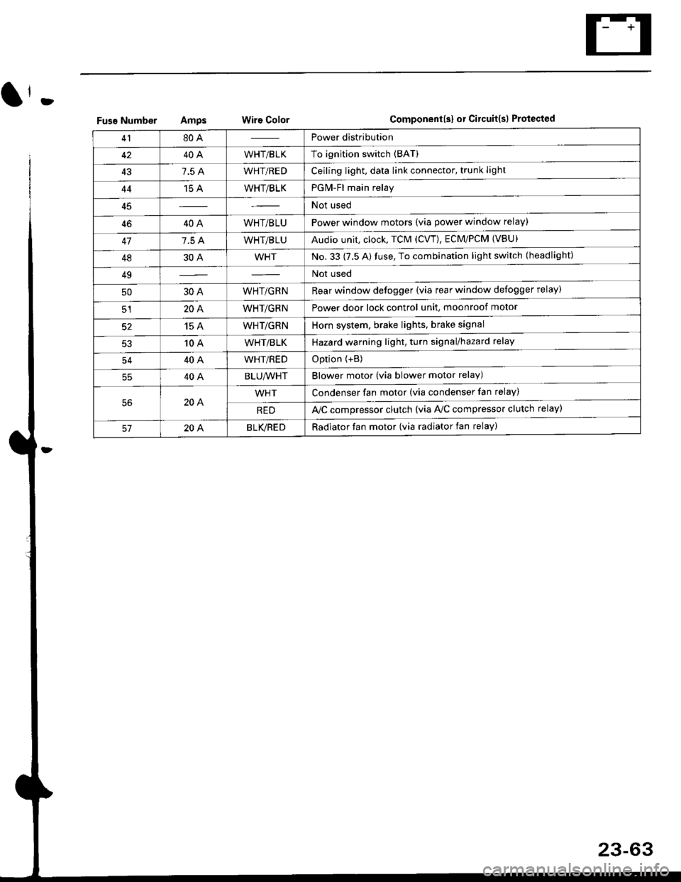
Fuse NumberAmpswire ColorComponent(s) or Circuitlsl Protect€d
4180APower distribution
4240AWHT/BLKTo ignition switch (BAT)
437.5 AWHT/REDCeiling light, data link connector, trunk light
4415 AWHT/BLKPGM-Fl main relay
Not used
4640AWHT/BLUPower window motors (via power window relay)
477.5 AWHT/BLUAudio unit, clock, TCM (CVT), ECM/PCM (VBU)
4830AWHTNo.33 (7.5 A) fuse, To combination light switch (headlight)
49Not used
5030AWHT/GRNRear window defogger (via rear window defogger relay)
cl20AWHT/GRNPower door lock control unit, moonroof motor
15 AWHT/GRNHorn system, brake lights, brake signal
10 AWHT/BLKHazard warning light, turn signal/hazard rclay
54404WHT/REDOption {+B)
5540ABLU,A/VHTBlower motor (via blower motor relay)
204WHTCondenser fan motor (via condenser fan relay)
REDl'lc compressor clutch (via IVC compressor clutch relay)
204BLVBEDRadiator fan motor (via radiator fan relay)
23-6
Page 1602 of 2189
![HONDA CIVIC 1999 6.G Workshop Manual Gauge Assembly
(Wnh lachomolgr)
I cNfldt--]I CONTRoL II MODULE
I 0cM) :
tvl
i.ll
|
-i;,
i
TURN SIGNAUHAZAROWARNINGswtTcH
Circuit Diagram {contd)
Fh"lurous @)- BLrcwHT + BLKryEL
fiSfvrous 16r.- veL HONDA CIVIC 1999 6.G Workshop Manual Gauge Assembly
(Wnh lachomolgr)
I cNfldt--]I CONTRoL II MODULE
I 0cM) :
tvl
i.ll
|
-i;,
i
TURN SIGNAUHAZAROWARNINGswtTcH
Circuit Diagram {contd)
Fh"lurous @)- BLrcwHT + BLKryEL
fiSfvrous 16r.- veL](/manual-img/13/6068/w960_6068-1601.png)
Gauge Assembly
(Wnh lachomolgr)
I cNfldt--]I CONTRoL II MODULE
I 0cM) :
tvl
i.ll
|
-i;,
i
TURN SIGNAUHAZAROWARNINGswtTcH
Circuit Diagram {cont'd)
Fh"lurous @)- BLrcwHT + BLKryEL
fi'Sfvrous 16r.- veLPAGE
RIGHT
V
IGR&ryE
LEFT
V
I
No.s (104)FUSE
V
IBEO/GRN
lru
8LU4RE0
ABSCONTROLUNIT
-rl
eLui'rvrr
G401G402G401G442
23-132