Page 1461 of 2189

Compressor (DENSO)
Replacement
1.lf the compressor is marginally operable, run the
engine at idle speed, and let the air conditioning work
for a few minutes, then shut the engine off
Disconnect the negative cable from the battery'
Recover the refrigerant with a recovery/recycling/
charging station lsee page 22-271
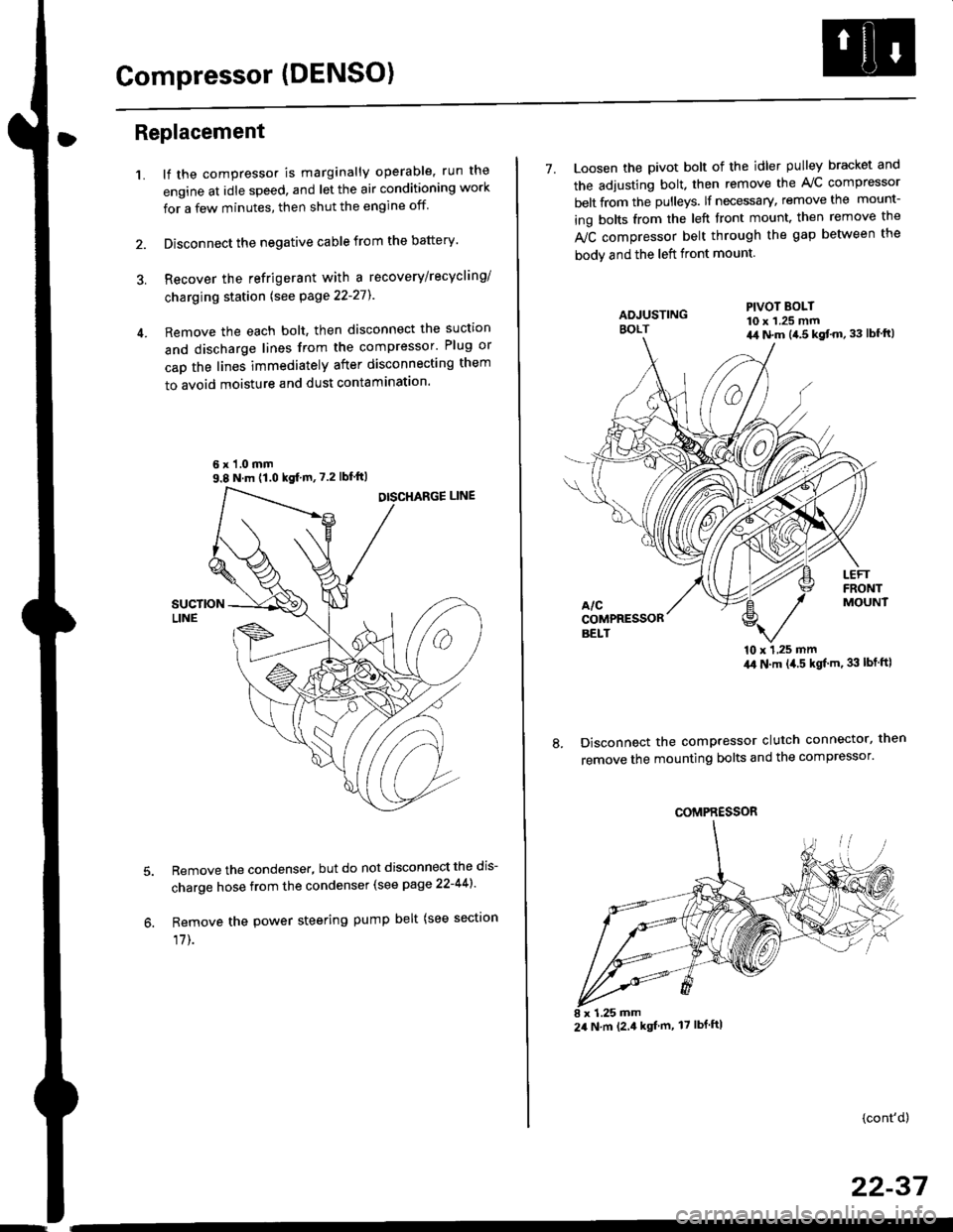
Remove the each bolt, then disconnect the suction
and discharge lines from the compressor' Plug or
cap the lines immediately after disconnecting them
to avoid moisture and dust contaminatlon.
6 x '1.0 mm9.8 N.m (1.0 kgf m,7.2 lbfft)
Remove the condenser, but do not disconnect the dis-
charge hose from the condenser (see page 22-441'
Remove the power steering pump belt (see sectron
17]-.
7. Loosen the pivot bolt of the idler pulley bracket and
the adjusting bolt. then remove the A,/C compressor
belt from the pulleys. lf necessary, remove the mount-
ing bolts from the left front mount. then remove the
fuC compressor belt through the gap between the
bodv and the left front mount.
'10 x 1,25 mm4,0 N.m (,1.5 kgf'm. 33 lbt ftl
Disconnect the compressor clutch connector, then
remove the mounting bolts and the compressor'
PIVOT BOLT10 x 1.25 mm4,1 N.m (4.5 kgt'm,33 lbfft)
COMPRESSOR
24 N.m (2.4 kgf m, 17 lbf ftl
(cont'd)
22-37
Page 1468 of 2189

Condenser
Replacement
1.Recover the refrigerant with a recovery/recycling/
charging station lsee page 22-271.
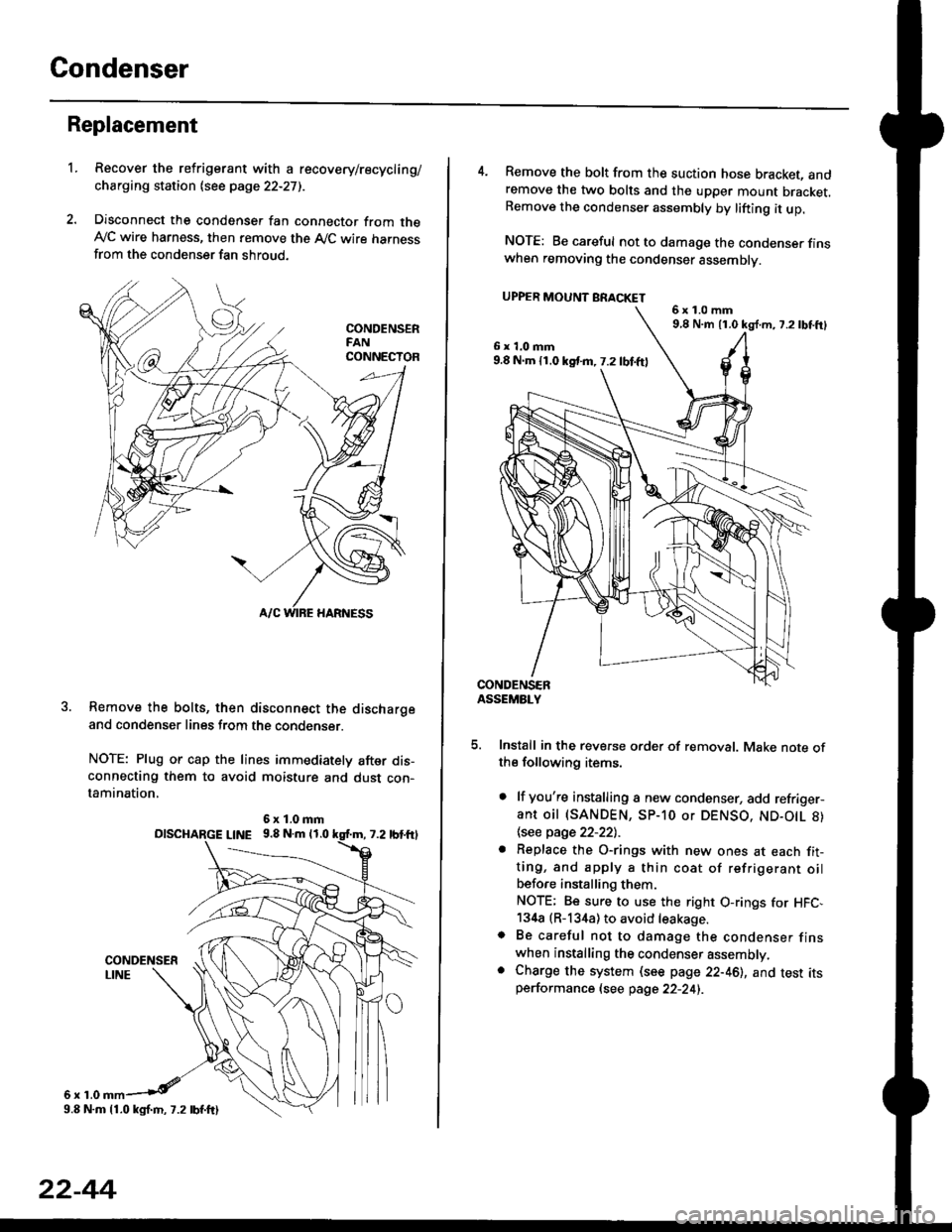
Disconnect the condenser fan connector from theAy'C wire harness, then remove the A,/C wire harnessfrom the condenser fan shroud.
Remove the bolts, then disconnect the dischargeand condenser lines from the condenser.
NOTE: Plug or cap the lines immediately after dis-connecting them to avoid moisture and dust con-tamination,
6r1.0
6x1.0mmolscHARGE L|NE 9.8 N.m 11.0
9.8 N.m 11.0 kgl.m, 7.2 lbf.ftl
22-44
4. Remove the bolt from the suction hose bracket, andremove the two bolts and the upper mount bracket.Remove the condenser assembly by lifting it up.
NOTE: Be careful not to damage the condenser finswhen removing the condenser assembly.
UPPER MOUNT BRACKET
5. Install in the reverse order of removal. Make note ofthe following items.
. lf you're installing a new condenser, add refriger-ant oil (SANDEN, SP-10 or DENSO, ND-O|L 8)
\see page 22-22l.-
. Replace the O-rings with new ones at each fit-ting, and apply a thin coat of refrigerant oilbefo.e installing them.
NOTE; Be sure to use the right O-rings for HFC,134a (R-134a) to avoid leakage.o Be careful not to damage the condenser finswhen installing the condenser assembly.. Charge the system (see page 22-46), and test itsperformance (see page 22-24i.
6x1.0mm9,8 N.m 11.0 kg{.m, 7.2lbtft}
6x1.0mm9.8 N.m 11.0 kst m, 7.2 lbf.ftl
Page 1957 of 2189

- How the Circuit Works
Battery voltage is supplied through tuse 56 to the
A,/C compressor clutch r€lay contacts at all times.
With the ignition switch in ON (ll), vollage is applied
to the coil of the A,/C compressor clutch relay
through fuse 17. When you push the A,/C switch
ON, and the heater fan switch is in position | , 2, 3,
or 4, a "ground" input is provided to the engine
control module (ECM) or powertrain control module
(PCM) through the l'lC thermostat and the l'lC
pressure switch.
The A,/C compressor clutch relay is grounded by the
engine control module (ECM) or powertrain control
module (PCM). When energized, the A'lC
compressor clutch relay allows battery voltage to
turn on the A,/C comDressor clutch.
The A,/C ON indicator light comes on when the A,/C
system is requested.
A,/C Thermostat
The A'lC thermostat is located on the evaoorator
housing. The A,/C thermostat turns off the A,/C
compressor clutch if the temperature at the
evaporator goes below 3'C (37'F). This prevents
condensation from freezing on the evaporator fins
and blocking the air delivery into the passenger
compartment. The blower motor will keep running
when the sensor turns off the comDressor.
A,/C Pressure Switch
The fuC oressure switch is located in the condenser
outlet line where refrigerant is in a high
temperature/high pressure liquid state. The switch
will sense abnormally high or low pressure, and
open the circuit. This removes ground, and the
compressor will stop running.
Thermal Protectot
The thermal protector, located on the A,/C
compressor, opens and turns the compressor off if it
senses high temperature. Once the compressor
cools, the switch will close and the compressor will
begin running again.
Refer to the Service Manual (Section 22,
Air Conditioning) for specific tests or
troubleshooting procedures.
62-3