Page 145 of 2189
Rocker Arms and Lost Motion Assemblies
Inspection (D16Y5, Dt6Y8 enginesl
NOTEr When reassembling the primary rocker arm,carefully apply air pressure to the oil passage of therocker arm.
1. Inspect the rocker arm piston. push it manually.- lf it does not move smoothly, replace the rockerarm assembty.
Dl6Y5 engine:
ROCKER ARM
TIMING PISTON
TIMING SPRING
SYNCHRONTZINGPISTON
SECONDARYROCKER ARM
MID ROCKER ARM
PRIMARY ROCKER
SYNCHRONIZINGPISTON A
NOTE:
. Apply oil to the pistons when reassembling.o Bundle the rocker arms with a rubber band to preventthem from separating.
6-34
(\
DI6YS engine:
NOTE: Set the timing plate and return spring as shownoerow.
RETURN
CAMSHAFT HOLDER
Dl6Yg engine:
2. Remove the lost motion assembly from the holderand inspect it. Test it by pushing the plunger withyour finger.- lf the lost motion assembly plunger does notmove smoothly, replace it.
LOST MOTION ASSEMBLY
\a
Pu3h
I
Page 148 of 2189

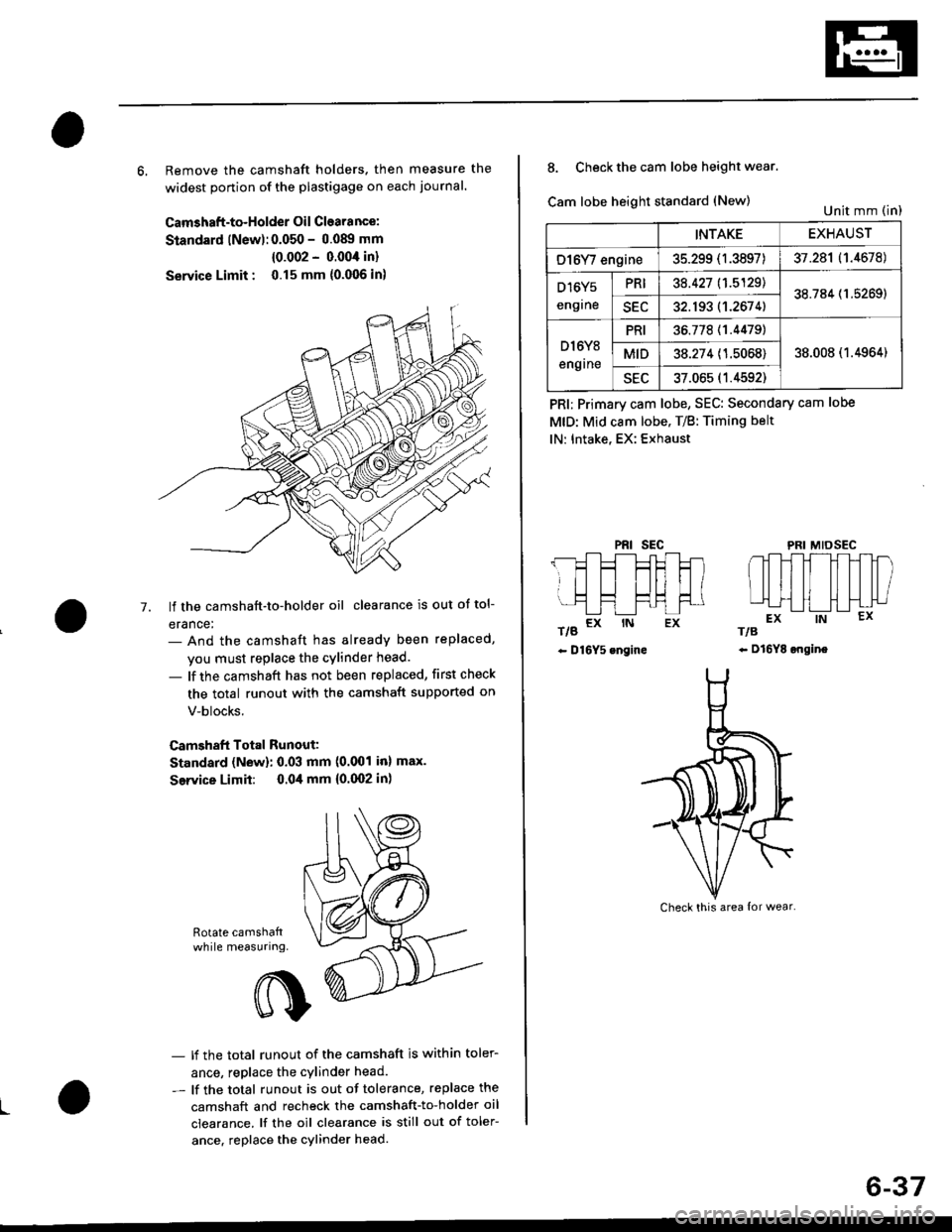
6, Remove the camshaft holders. then measure the
widest ponion of the plastigage on each journal.
Camshaft-to-Holder Oil Clearance:
Standard lNew):0.050 - 0.08!t mm
{0.002 - 0.004 in}
Service Limit : 0.15 mm {0.006 in)
lf the camshaft-to-holder oil clearance is out ot tol-
erance:- And the camshaft has already been replaced,
you must replace the cylinder head.
- lf the camshaft has not been replaced, first check
the total runout with the camshaft supported on
V-blocks.
Camshaft Total Runout:
Standard (New): 0.03 mm (0.001 inl max.
Service Limit: 0.04 mm {0.(X)2 in)
-7.
Rotate camshattwhile measuring.
L
- lf the total runout of the camshaft is within toler-
ance, replace the cylinder head.
- lf the total runout is out of tolerance, replace the
camshaft and recheck the camshaft-to-holder oil
clearance. lf the oil clearance is still out of toler-
ance. replace the cylinder head.
INTAKEEXHAUST
O16Y/ engine35.299 (1.3897)37.281 (1.4678)
D16Y5
engrne
PRI38.427 11.5129138.784 (1.5269)
SEC32.193 (1.2674)
D l6Y8
engrne
PRI36.77811.44791
38.008 (1.4964)MID38.274 (1.5068)
sEu37.065 (1.4592)
8. Check the cam lobe height wear.
Cam lobe height standard (New)
t/g a* rN Ex
- D16Y5 engine
PRI; Primary cam lobe, SEC: Secondary cam lobe
MtD: Mid cam lobe. T/B: Timing belt
lN: Intake, EX: Exhaust
PRIsEcMIDSEC
rts
- Dl6YE ongine
Unit mm (in)
Check this area {or wear.
6-37
Page 165 of 2189

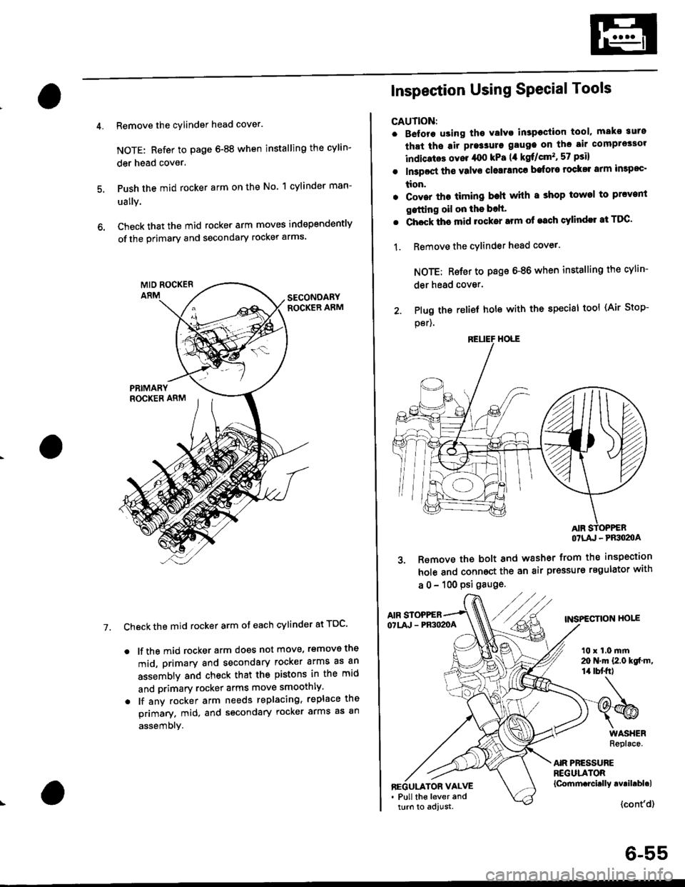
Remove the cylinder head cover.
NOTE: Refer to page 6-88 when installing the cylin-
der head cover.
Push the mid rocker arm on the No. 1 cylinder man-
ually.
Check that the mid rocker arm moves independently
of the primary and secondary rocker arms.
Check the mid rocker arm ot each cylinder at TDC'
. lf the mid rocker arm does not move, removs the
mid, primary and secondary rocker arms as an
assembly and check that the pistons in the mid
and primary rocker arms move smoothly.
. lf any rocker arm needs replacing, replace the
primary. mid, and secondary rocker arms as an
assembly.
7.
2. Plug the
per).
Inspection Using SPecial Tools
CAUTION:
. B€fore using tho Yalvo inspeciion tool, mako suro
that ths air pre3sure gauge on the air comprossor
indicatos ovor /rco kPa (,1 kgf/cm'�, 57 psi)
. In3poct ths valve closranca bafore rock$ arm impoc'
tion.
. Cover the timing beh whh I shop towel to prcvenl
gstting oil on the bolt'
. Chock ths mid rocker arm of each cylindll at TDC'
1. Remove the cYlinder head cover.
NOTE: Rsfer to page 6-86 when installing the cylin-
der head cover.
relief hole with the special tool (Air Stop-
OTLA' - PRSO2OA
3. Remove the bolt and washer from the inspection
hole and connoct the an air pressure regulator with
a 0 - 100 psi gauge.
AIF STOPPEBTNSPECTION HOIEOTLA' - PR3O2OA
t0 x 1.0 mrn20 N.m {2.0 kgf m,14 tbt'fr)
AIR PRESSUREREGULATOR{Cornm.rcirlly avril.bl.lBEGULATOR VALVE. Pull the lever andturn to adjust.{cont'd}
6-55
Page 166 of 2189
VTEC Rocker Arms
4.
Inspection Using Special Tools (cont,dl
Loosen the valve on the regulator and apply thespecified air pressure.
Specified Air Pressuro:
250 kPa {2.5 kgtlcm,, 36 psil- 490 kPa {5.0 kgtcm,, 7t psil
Make sure that the primary and secondary rockerarms are mechanically connected by the pistonsand that the mid rocker arms do no. move wnenpushed manually.
SECONDARYROCKER ARM
. lf any mid rocker arm moves independently ofthe primary and secondary rocker arms, replacethe rocker arms as a set.
Remove the tools.
Check the operation of the lost motion assembly bypushing on the mid rocker arm. The lost motionassembly should compress fully and operatesmoothly through its full stroke. Replace the assem_bly if it does not work smoothly.
After inspection. check that the Malfunction Indi_cator Lamp {MlL) does not come on.
7.
6-56
I
ll
;l
Page 179 of 2189
WATER BYPASS
HOSE
14. Remove the upper radiator hose, heater hose and
water bvpass hose.
HEATER
Remove the engine wire harness connectors and wlre
harness clamps from the cylinder head and the intake
manifold.
Four fuel injector connector
Engine coolant temperature (ECT) sensor connec-
tor
ECT gauge sending unit connector
ECT switch connector
ldle air control (lAC) valve connector
Manifold absolute pressure (MAP) sensor connec-
tor
Throttle position sensor connector
Primary Heated oxygen sensor (Primary HO2S)
connecror
VTEC solenoid valve connector
15.
a
a
a
a
a
\
16.
17.
Remove the spark plug caps and distributor form
the cylinder head.
Remove the upper bracket.
NOTE:
. Use a jack to support the engine before removing
the upp€r bracket is removed.
. Place a cushion between the oil panandthejack.
12 x 1.25 fin74 N.m 17.5 kgtm,
UPPER BRACKET
18. Remove the cylinder head cover.
{cont'd)
6-69
Page 183 of 2189
Rocker Arms and Lost Motion Assemblies
Inspection
NOTE: When reassembling the primary rocker arm, care-
fully apply air pressure to the oil passage of the rocker
arm.
PRIMARY ROCKER ARM
MID ROCKER ARM
Inspect each rocker arm piston. Push it manually
- lf it does not move smoothly. replace the rocker
arm assemDly.
1.
SECONDARY
Check prston movement
NOTE:
. Apply oilto the pistons when reassembling.
. Bundle the rocker arms with a rubber band to
keep them together as a set.
PISTONS
PRIMARY
\
6-73
2. Remove the lost motion assembly from the cylinder
head and inspect it. Test it by pushing the plunger
with your finger,
- lf the lost motion assembly does not move
smoothly, replace it.
LOST MOTION ASSEMBLY
Push
I
Page 184 of 2189
Rocker Arms and Shafts
Clearance Inspection
Measure both the intake rocker shaft and exhaust rocker
shaft.
1. Measure diameter of shaft at the first rocker loca-
tron.
2. Zero gauge to shaft diameter.
Surlace shor/ld be smooth.
MICROMETER
6-74
3. Measure the inside diameter of each rocker arm and
check for out-of-round condition
Rocker Arm-to-Shaft Clearance:
Intake and Exhaust
Standard {Newl: 0.025 - 0.052 mm
{0.0010 - 0.0020 in)
Service Limit: 0.08 mm {0.003 in)
Inspect rocker armface for wear.
Repeat for all rockers.- lf over limit, replace rocker shaft and all overtol-
erance rocker arms.
NOTE: lf any rocker arm needs replacement, replace
all three rocker arms in that set {primary, mid, and
seconoary).
Page 186 of 2189

Gamshafts
Inspection (cont'dl
7. lf the camshaft-to-holder oil clearance is out of tol-
erance:
- And the camshaft has already been replaced, you
must replace the cylinder head.- lf the camshaft has not been replaced, first check
the total runout with the camshaft supported on
V-blocks.
Camshaft Total Runout:
Standard (New): 0.03 mm {0.001 in} max.
Service Limit: 0.04 mm (0.002 inl
- lf the total runout of the camshaft is within toler,
ance, replace the cylinder head.- lf the total runout is out of tolerance. replace the
camshaft and recheck the camshaft to,holder oil
clearance. lf the oil clearance is still out of toler-
ance, replace the cylinder head.
INTAKEEXHAUST
PRIMARY33.088 mm
{1.3027 in)
32.785 mm
(1.2907 inl
MID36.267 mm(1.4278 in)
35.720 mm
{1.4063 in)
SECONDARY34.978 mm(1.3771 inl
3i1.691 mm(1.3658 in)
8. Check the cam lobe height.
Cam lobe height standard (New):
Cam Position
I
INTAKE
MID
EXHAUST
SEC MID PRI
TIB
T/B: TIMING BELTPRI: PRIMARYMID: MID
Check thrs area lor wear.