1999 HONDA CIVIC junction
[x] Cancel search: junctionPage 1819 of 2189
How To Use This Manual
Circuit Schematics
oa
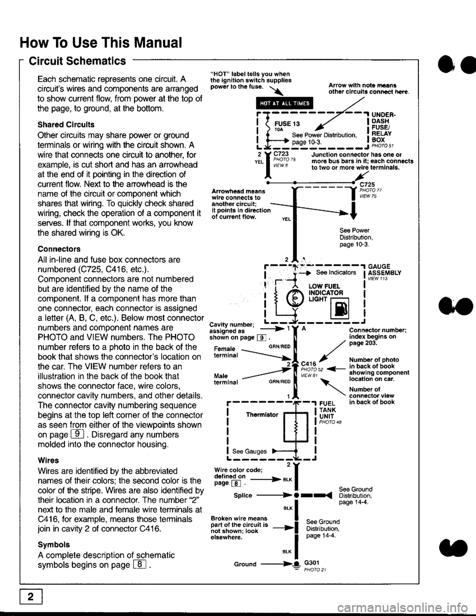
Each schematic represents one circult. A
circuit's wires and components are arranged
to show current flow, from power at the top of
the page, to ground, at the bottom.
Shared Circuits
Other circuits may share power or ground
terminals or wiring with the circuit shown. A
wire that connects one circuit to another, for
example, is cut short and has an arrowhead
at the end of it pointing in the direction of
current flow. Nelit to the anowhead is the
name o{ the circuil or comoonent which
shares that wiring. To quickly check shared
wiring, check the operation of a component it
serves. lf that component works, you know
the shared wiring is OK.
Connectors
All in-line and fuse box connectors are
numbered (C725, C416, etc.).
Component connectors are not numbered
but are identiJied by the name of the
component. lf a componenl has more than
one connector, each connector is assigned
a letter (A, B, C, etc.). Below most connector
numbers and comDonent names are
PHOTO and VIEW numbers. The PHOTO
number refers to a Dhoto in the back of the
book that shows lhe conneclor's location on
the car. The VIEW number refers to an
illustration in the back of the book that
shows the connector face, wire colors,
connector cavity numbers, and other details.
The connector cavity numbering sequence
begins at the top left corner oJ the connector
as seen from either of the viewooints shown
on page ffl . Disregard any numbers
molded into the connector housino.
Wires
Wires are identilied by the abbreviated
names of their colors; the second color rs the
color of the stripe. Wires are also identified by
their location in a connector. The number '2"
next to the male and female wire terminals at
C416, for example, means those terminals
join in cavity 2 of connector C416.
Symbols
A complete description of schematic
symbols begins on page | 8
"HOT" label tells you whenthe ignition switch suppliespower to the fuse. \
Artowhead meanswire connects toanother circuit;
Arrow with note rErngother circuils conncct h€re.
it .a
llu":: ^,{ ii t See Power Distribution, .I t----t oaqe tO-3. IL*--:--------J2 Y C723 Junction connectorYEL I Pao'o'8 more bus bars in it;
I - " " to two or more wire
l,/
-t>?
See PowerDistribution,page 10-3.
UNDER.DASHFUSE/RELAYBOX
has one oleach connactgterminala.
it ooints in directionof current flow.
TheImletor
t_I
Cavity number; L ---
Jiili'iJi!--' -----> '
shoin on page S .
Maleterminal
L?*?l?,-
"'"'I
c725
vlEUt/ 75
Connector number;index begins onpage 203.
Number ot photoin back ol bookshowing componentlocation on cat.
Number ofconneclor viewin back of book
7
GBN/FEO
See Ground
Soe Indicators I ASSEMBLY
:-------J
LOW FUELINDICATOFLIGHT r-l
EI
A
"o'r"/PHOTO 52 <-
\
FUELTANKUNIT
Splice ---------) O rr
".* I Page 14'4'
IBroken wire means | --^ -
iar";J.'It,;,rJ;ii; -----i Bffi,Bili*l
elsewhere. I 0a0e tn-a
IBrK Icround --->lL c301: ptioro 21
Page 1862 of 2189
- G402
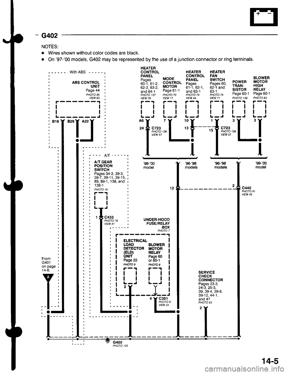
NOTES:
. Wires shown without color codes are black.
. On '97-'00 models, G402 may be represented by the use of a junction connector or ring terminals.
with ABS - - - - - I
. ABS CONTROL I' ultt '
HEATERCONTROL HEATER HEATER
iili, BB-'fi",. Eiff* 5fi::g PowER i,8;g'"'
;;; ;;; MoroR ;il--"'. ;;1-;; rRAN- H|GH
!if,6f1- ease ot-t Ino b5-.t ' fi i *- slsroR FELAY- ,pHaTa t3z pHoro 70 photoT. iioro ^ Page 60-1 Page 60-1vtEw 76 vlEW 17 V|EW 44 V|EW11 PHOTO139 PHOTO 83
r-1r-.!r-1r-1r-.|r-1
| | | | | | rl I lll
| | | | | | I ll ll IL-J L-J L-J L.J L-J L-J
Page 44PHOTO 85vtEW 63
I
I------J
I""IJ
Ifnn*"1 r'[
1"""LI'--- A/l ---_r
i , m cean; I POStflON, : swrrcH :' , Pages 34-3, 39-3, :' | 39-7,39-11,39-15,;: ' 89, 89-1, 138, and ,
; : 138-1| | PHO|OIA :' , F-'t .
'99-'00
mooel
'96-'�98
moo€ts
'9G'S
mod6ls
'99-'00
modol
a
12c440
vtEw 45
FromG401on page14-6.
v
l-
SERVICECHECKCONNECTORPages 23-3,24-3,25-3,39, 39-4, 39-8,39-12,44-1,afid 47
c402
I
I
3 cass
l;l:,12,
li
rc i UNDER-HOOD, FUSE/RELAYBOXPHAfa 7
I elecrRrca- |I LOAD BLOWER I: DETECTOR MOTOR iI (ELD) RELAY II UNlf Paoe 60 |
a W.': :;ffil iI r-r F-'r I
tt | | | |
tr | | | |I L-J L-J I
i 'r Y iL--+---J--J
I
'I&%,14.,I
14-5
Page 1958 of 2189
Fans
- AllModels\,1 |
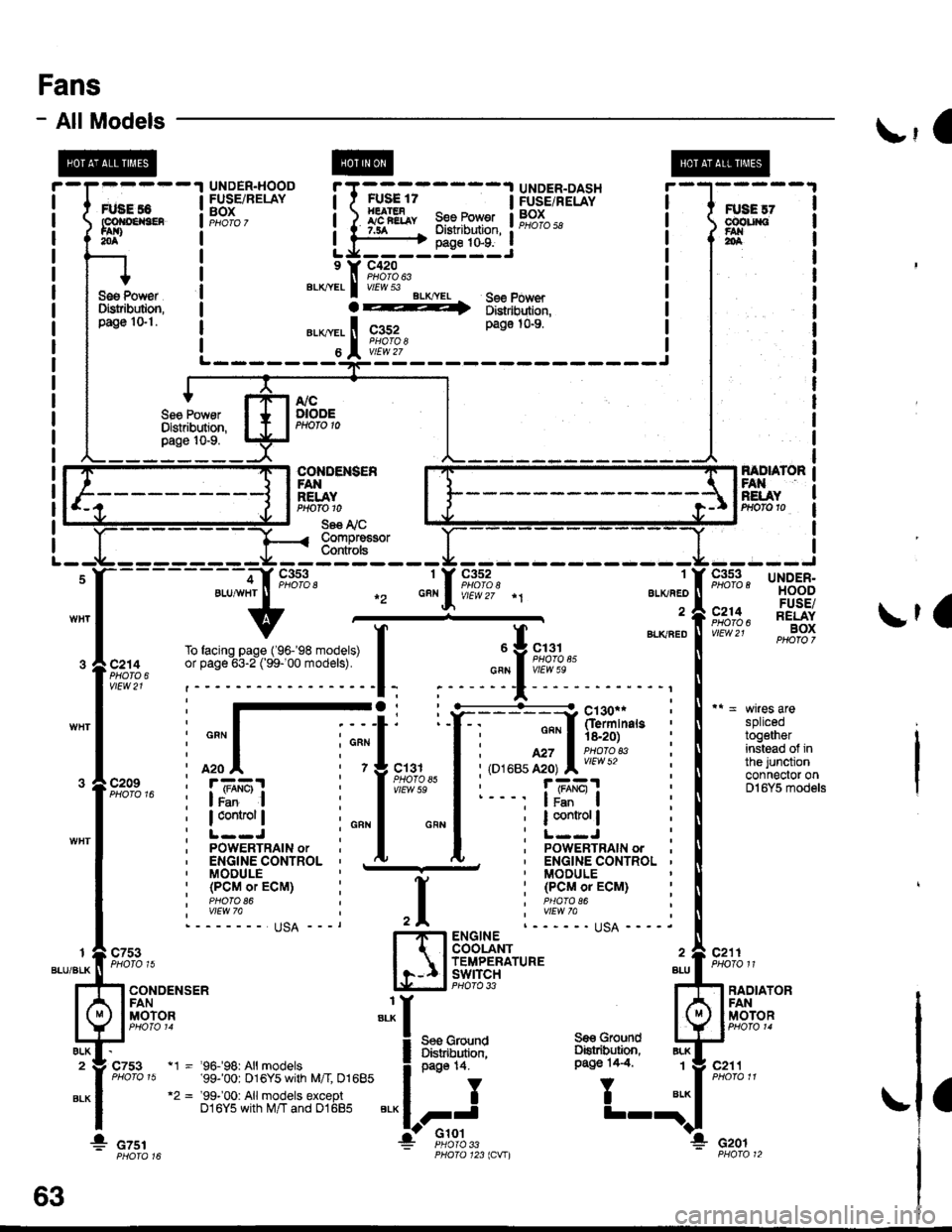
splicedtogetherinstead of inthe junctionconnector onDl6Y5 models
c211PHOTO 11
FANRELAYPrtofo 10
Se€ I'i CCompre€sorCont ols
1
ALKAED
a
c352
f BLKaEou Y 9,;%,.cFN I vIEw 5e
;
"'
T
";::-:.."-!
Y:. ---::Y h!ii'in"," :
I : ""'I 'is.2o) :
I i,o''ur,ff;, l;l:'l?'* i
I r- - -, |JBEI :
I ; I control | ;
I :L--J :I ' PoWERTRAIN ordu. ' ENGINE CONTROL '' MODULE
: (PCMoTECM) :I PHAfO 86I wEw 7allqA ----.ENGINECOOLANTTEMPERATUREswtrcH BLLPHO|O 33 ?
Ses GrolndDiskibution,oaqe 14.
,I
H
:I
i:
"'*
1_l
c7531
BLU/BLK
ALK2
BLK
RADIATORFANMOTORI
BLK
BLK1
ELK
c753
CONDENSERFANMOTOR
a
* czsr
page 14.
II
FJ'Glot
c211
Gro!nd
T
Se€ GroundOstribution,Pago 14.4"t1 - '96.f98: All models'99-'00: 016Y5 with M/I 01685"2 = '99-'00: Allmodels exceptD16Y5 with M/T and 01685
cof{oENs€R
* czor33123lCVIl
63
Page 2117 of 2189
Connector Views (cont'd)
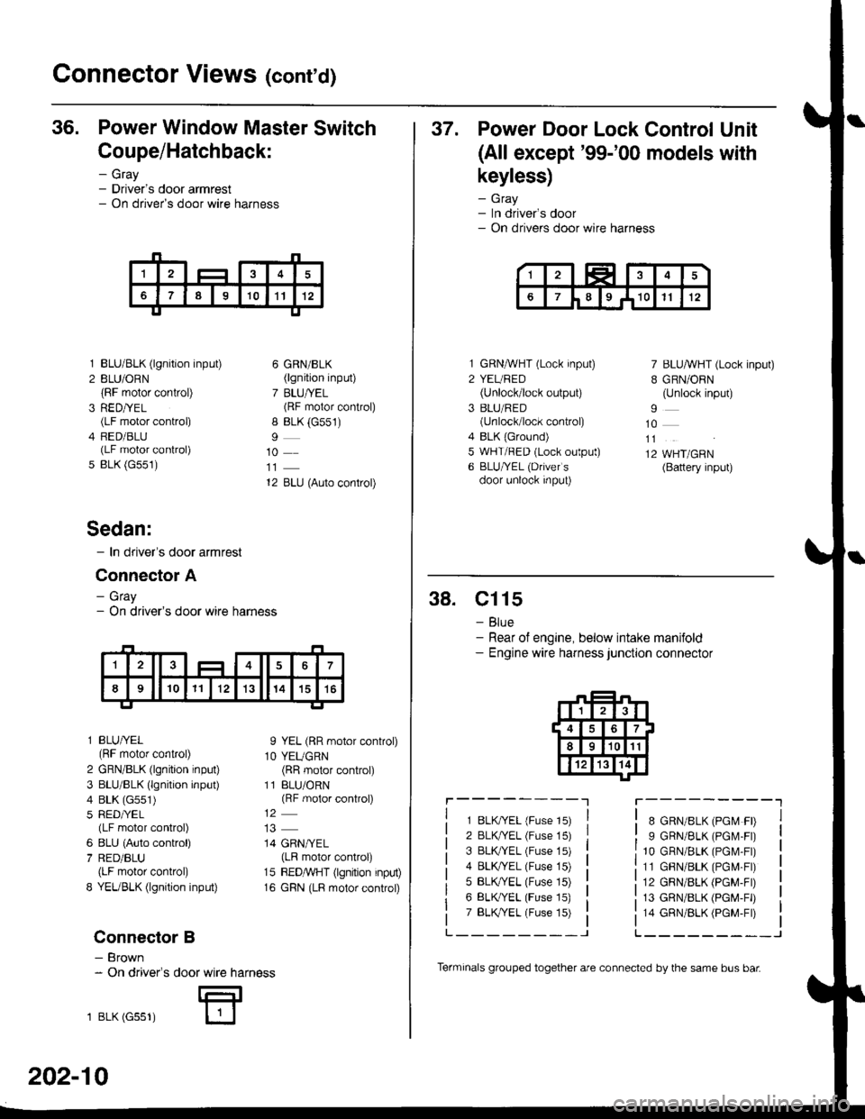
36. Power Window Master Switch
Coupe/Hatchback:
- Gray- Driver's door armrest- On driver's door wire harness
3
5
BLU/BLK (lgnition input)
BLU/ORN(RF motor control)
RED/YEL(LF motor control)
FED/BLU(LF motor control)
BLK (G551)
6 GRN/BLK(lgnition input)
7 BLU/YEL(RF motor control)
8 BLK (G551)
10
12 BLU (Auto control)
I YEL (RR motor control)
1O YEUGRN(RR motor control)
11 BLU/ORN(RF motor control)
14 GRN/YEL(LR motor control)
15 REDMHT (lgnition input)
16 GRN (LR motor control)
Sedan:
- In driver's door armrest
Connector A
- Gray- On driver's door wire harness
l BLU/YEL(RF motor control)
2 GRN/BLK (lgnition input)
3 BLU/BLK (lgnition input)
4 BLK (G551)
5 RED/YEL(LF motor control)
6 8LU (Auto control)
7 RED/BLU(LF motor control)
8 YEUBLK (lgnition input)
Connector B
- Brown- On driver's
1 BLK (Gss1)
door wire harness
E
202-10
Terminals grouped together are connected by the same bus bar
37. Power Door Lock Control Unit
(All except'99-'00 models with
keyless)
- Gray- In driver's door- On drivers door wire harness
1 GRNMHT (Lock input)
2 YEURED(Unlock/lock output)
3 BLU/RED(unlock/lock control)
4 BLK {Ground)5 WHT/RED (Lock output)
6 BLU/YEL (Drivefs
door unlock input)
7 BLU/WHT (Lock input)
B GRN/ORN(Unlock input)
10
11
12 WHT/GRN(Battery input)
38. Cl15
- Blue- Rear of engine, below intake manifold- Engine wire harness junction connector
r----------lr---------"1
1 8LK?ryEL (Fuse 15)
2 BLK/YEL (Fuse 15)
3 BLK TEL (Fuse 15)
4 BLK/YEL (Fuse 15)
5 BLK,/YEL (Fuse 15)
6 BLK/YEL (Fuse 15)
7 BLK,TYEL (Fuse 15)
8 GRN/8LK (PGM FD
9 GRN/BLK (PGM.FD
10 GRN/BLK (PGr\,4-Fr)
11 GBN/BLK (PGM-Fr)
12 GRN/BLK (PGM-FD
13 GRN/BLK (PGM-FD
14 GRN/BLK (PGM-Fr)
L_______-JL______--_J
Page 2118 of 2189
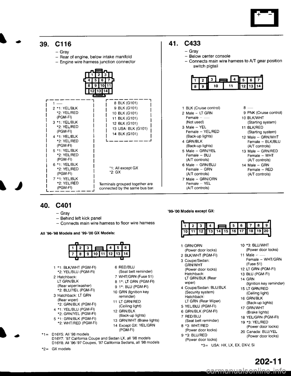
-39. Cl16
- Gray- Rear ol engine, below intake manifold- Engine wire harness junction connector
41. C433
- Gray- Below center console- Connects main wire harness to A'/T gear position
switch pigtail
i-'-j-----lr-:-_-::::^-_---'18 BLK (G101)
s BLK (G101)
10 BLK (G101)
11 BLK (G101)
12 BLK (G101)
13 USA: BLK (G101)
14 BLK (G101)
L___-----J
2 *1: YEL/BLK*2iYEURED
(PGM-Fr)
3 *1: YEUBLK
(PGl\4-Fr)
4 *l:YEUBLK*2T YEURED(PGr\4-F|)
5 *1i YEL/BLK*2: YEURED(PGM-Fr)
6 *1: YEUBLK*2: YEURED(PGM Fr)
7 *1: YEUBLK*2: YEURED
1 BLK (Cruise conlrol)
2 l\,1ale - LT GRNFemale(Not used)
3 Male - YELFemale - YEURED(Back-up lights)
4 GRN/BLK(Back-up lights)
5 f,rale - GRN/YELFemale - BLU(A,/T controls)
6 l\.4ale - GRN/BLUFemale GRN(A,/T controls)
7 Male - GRN/ORNFemale - YEL(A/T conkols)
9 PNK (Cruise control)
1O BLI(WHT(Starting system)
11 BLI(RED(Starting system)
12 Male - GRNIVHTFemale - BLK/BLU(A,/T controls)
13 Male - GRN/REDFemale - WHT(A,/T controls)
14 Male - GRNFemale - RED(A,/T controls)
L_i9yj'L____i
'1: Allexcept GX'2: GX
Terminals grouped together areconnected by the same bus bar.
40. c401
- Gray- Behind left kick panel- Connects main wire harness to floor wire harness
All '96-'98 Models and '99100 GX Models:
1 *1: BLKWHT (PGM-F|)*2:YEL/BLU (PGl\4'Fl)
2 HatchbackiLT GRN/BLK(Rear wiper/washer).2: BLU/YEL {PGM-Fl)
3 Hatchback: LT GRN(Rear wiper).2: GRN/BLK (PGM'Fl)
4 *1:YEUBLU (PGM Fl)*2: GRN/VEL (PGl,I-Fl)
5 *1: GRN/BLK (PGM-FI)*2: WHT/RED (PGl\4-Fl)
*1= D16Y5iAll '98 modelsD16Y7r '97 California Coupe and Sedan LX, all '98 models
D16Y8: All '96-97 Coupes, '97 Calilornia Sedans, all '98 models
*2= GX models
'99-'00 Models except Gx:
6 BED/BLU(Seat belt reminder)
7 WHT/GRN (Fuse 51)
8 1.: LT GRN (PGM'F|)
I 1.i BLU (PGl\.4-Fl)
10 GRN (lgnition keyremrnoer)
11 LT GRN/RED(Ceiling light)
12 GRN/BLK(Back-up lights)
13 GFN,TVHT (Brake lights)
14 Except GX: YEUGBN
{PGM-Fr)
1 GRN/ORN(Power door locks)
2 BLK,ryVHT (PGM-Fl)
3 Coupe/SedaniGRNA/VHT(Power door locks)Hatchback:LT GRN/BLK (Rear
wiper)
4 Coupe/Sedan: BLU/BLK(Security system)Hatchback:LT GRN (Rear wipeo
5 YEUBLU (PGl\4-Fl)
6 GRN/BLK (PGM,FD
7 RED/BLU(Seat belt reminder)
8 *3: WHT/RED(Power door locks)
9 *3: BLU/RED(Power door locks)
10 '3: BLU^VHT(Power door locks)
11 l\.4ale -
Female - WHT/GRN(Fuse 51)
12 LT GRN (PGM-FD
13 BLU (PGr\4 Fr)
14 GRN(lgnition key reminder)
15 LT GRN/RED(Ceiling light)
16 GRN/BLK(Back-up lights)
17 GRN,ryVHT(Brake lights)
18 YEUGRN (PGI\4.FD
19 *3: YEURED(Power door locks)
20 Canada: BLU/YEL(Power door locks)-
*3= USA HX, LX, EX OX-V Si
202-11
Page 2122 of 2189
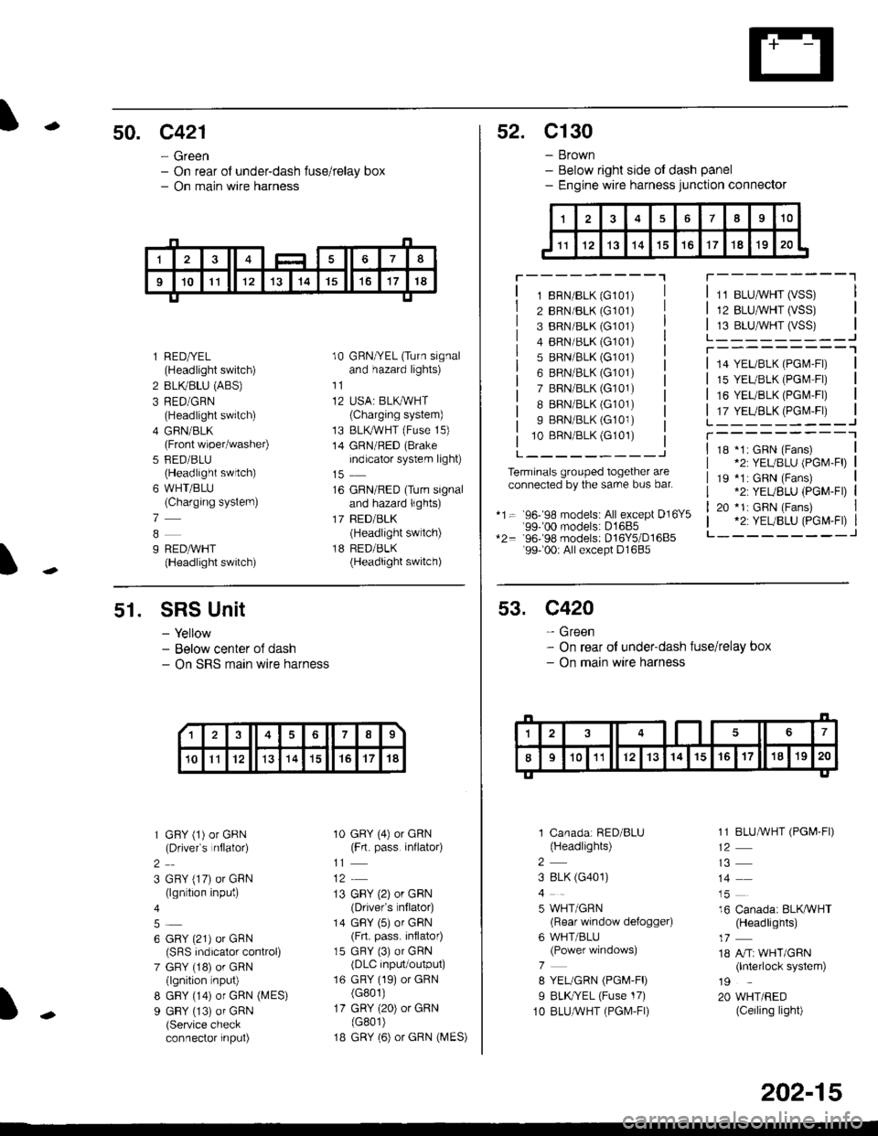
-50. c421
- Green- On rear of under-dash fuse/relay box- On main wire harness
I
l RED/YEL(Headlight switch)
2 BLIVBLU (ABS)
3 RED/GRN(Headlight switch)
4 GFIN/BLK(Front wiper/washer)
5 FED/BLU(Headlight swrtch)
6 WHT/BLU(Charging systern)
7
9 REDAVHT(Headlight switch)
10 GRN/YEL (Turn signaland hazard lights)
11
12 USA: BLKAVHT(Charging system)
13 BLKryVHT (Fuse 15)
14 GRN/RED (Brake
indicator system light)
16 GRN/RED (Turn signaland hazard lights)
17 BED/BLK(Headlight switch)
18 RED/BLK(Headlight switch)
52. C130
- Brown- Below right side ot dash panel- Engine wire harness junction connector
T---------"1
1 8RN/BLK (G101)
2 BRN/BLK (G101)
3 BRN/BLK (G101)
4 BRN/BLK (G101)
5 BRN/BLK (G101)
6 BRN/BLK (G101)
7 BRN/BLK (G101)
I BRN/BLK (G101)
9 BRN/BLK (G101)
10 BBN/BLK (G101)
L---------J
Terminals grouped together areconnected by the sarre bus bar.
*1= 96- 98 models: All except D16Y5'99-'00 models: D1685*2= 96-98 models: D16Y5/D1685'99- 00r All except D1685
11 BLUMHT (VSS)
12 BLU,ryVHT (VSS)
13 BLU,^/VHT (VSS)L_-_____--Jr---------'1
14 YEL/BLK (PGl\4-Fl)
15 YEL/BLK (PGr\4'Fr)
16 YEUBLK (PGI\4,FI)
17 YEUBLK (PGr\4,Fr)L______---JT----------118 *1: GRN (Fans)*2: YEUBLU (PGM-Fl)
19 *1: GRN (Fans).2: YEUBLU (PGM-Fl)
20 *1: GRN (Fans).2: YEUBLU (PGM-Fl)_______--J
51. SRS Unit
- Yellow- Below center oJ dash- On SRS marn wire harness
1 GFY (1) or GRN(Drivefs nflator)
2
3 GRY (17) or GRN(lgn tion input)
6 GRY (21) or GRN(SRS indicalor control)
7 GRY (18) or GRN(lgnition nput)
8 GBY (14) or GRN (MES)
9 GBY (13) of GRN(Service checkconnector input)
10 GRY (4) or GRN(Frt. pass. inflato4
11
13 GBY (2) or GRN(Drivefs nflator)
14 GBY (5) or GRN(Frt. pass. inflator)
15 GRY (3) or GRN(DLC input/output)
16 GRY (19) or GRN(G801)
17 GRY (20) or GRN(G801)
1B GRY (6) or GRN (MES)
13678
10Il12131415't7't8
53. C420
- Green- On rear of under-dash fuse/relay box- On main wire harness
1 Canadar RED/BLU(Headlights)
2
3 8LK (G401)
5 WHT/GRN(Rear window defogger)
6 WHT/BLU(Power windows)
7
8 YEL/GRN (PGM-FD
I BLK//EL (Fuse 17)
1O BLUAVHT (PGM,FI)
1 1 BLUMHT (PGI,4-FI)
14
16 Canada: BLKAVHT(Headlights)
18 A/Tr WHT/GRN(lnterlock system)
19
20 WHT/RED(Ceiling light)
202-15
Page 2123 of 2189
Connector Views (cont'd)
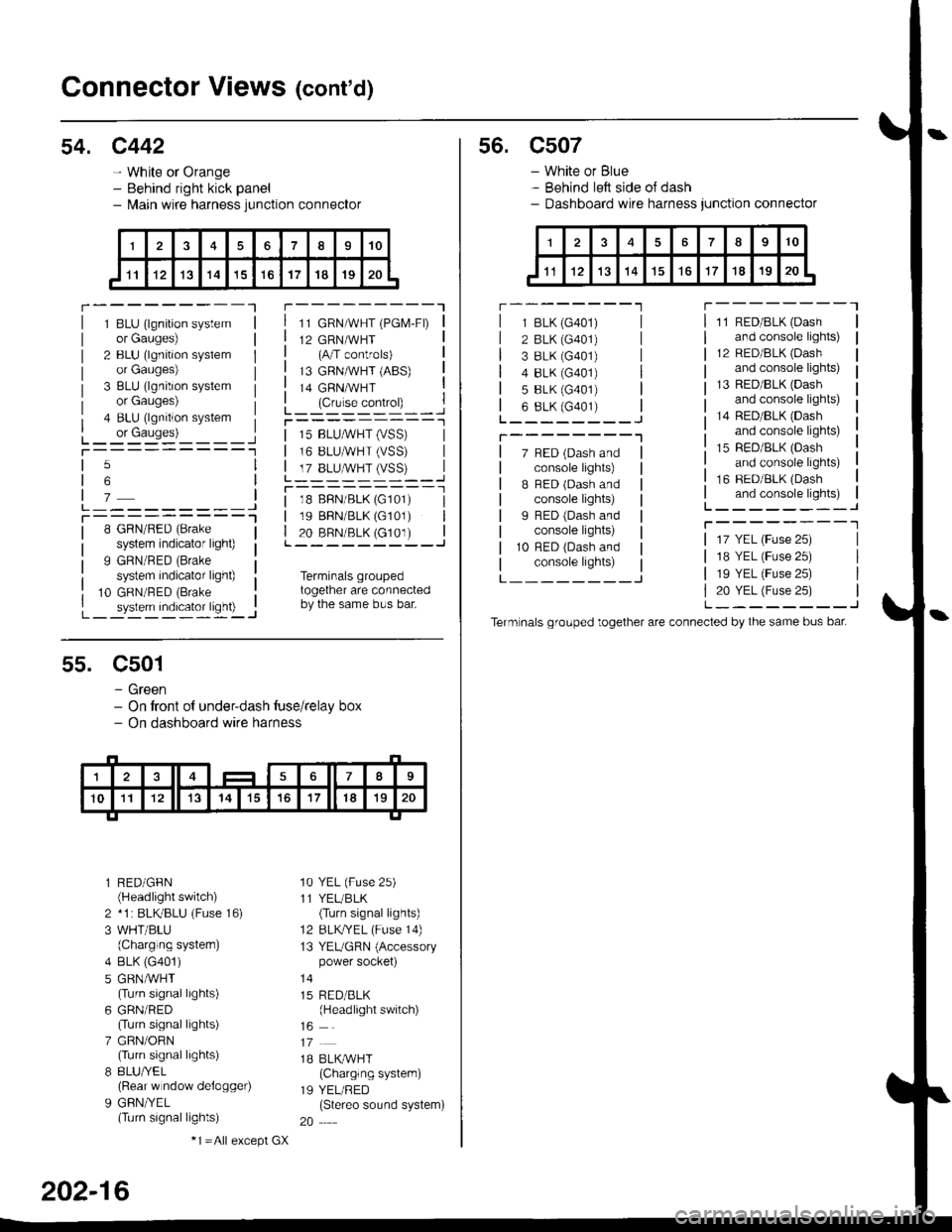
54. c442
- White or Orange- Behind right kick panel- l\,lain wire harness junction connector
r---------Tr---------"1
1 BLU (lgnition systemor Gauges)
2 BLU (lgnition syslemor Gauges)
3 BLU (lgnition systemor Gauges)
4 BLU (lgnition system
L_ or causes)L_-:-:::'-'�____Jt-----------1
11 GRN/WHT (PGM-FD
12 GRN/WHT(A/T controls)
13 GRNMHT (ABS)
14 GRNMHT
L_ lc,r'." .oIr"D_ _ _.jr----------_l
5
6
7L---------JT----------l8 GRN/RED (Brake
system indicator light)
9 GRN/RED (Brake
system indicator light)
10 GRN/RED (Brake
_ system indicator ligh0 -..1
| 15 BLUMHT (vSS) |I 16 BLUMHT (VSS) I
L T?_BLUSTrySS)--..]
l--------- - -l
| 18 BFN/BLK (G101) I| 19 BBN/BLK (G101) || 20 BRN/BLK (c101) |L---------J
Terminals groupedtogether are connectedby the same bus bar.
55. C501
- Green- On tront of under-dash tuse/relay box- On dashboard wire harness
l RED/GFN(Headlight switch)
2 *1 : BLKBLU (Fuse 16)
3 WHT/BLU(Charging systern)
4 BLK (G401)
5 GRNMHT(Turn signal lights)
6 GRN/RED(Turn signal lights)
7 GRN/ORN(Turn signal lights)
8 8LU/YEL(Rear w ndow delogger)
9 GFN/YEL(Turn signal lights)
'10 YEL (Fuse 25)
11 YEL/BLK(Turn signal lights)
12 BLKTYEL (Fuse 14)
13 YEUGRN (Accessorypower socket)
15 RED/BLK(Headlight switch)
1B BLK/WHT(Charglng system)
19 YEL/RED(Stereo sound system)
20
202-16
-1 =All e),cept GX
s6. c507
- White or Blue- Behind left side oJ dash- Dashboard wire harness junction connector
r --------'lT---------l
7 BED (Dash andconsole lights)
B BED (Dash andconsole lights)
I RED (Dash andconsole lights)
10 RFD (Dash andconsole lights)
11 RED/BLK (Dash
and console lights)
12 RED/8LK (Dash
and console lights)
13 RED/BLK {Dashand console lights)
14 RED/BLK (Dash
and console lights)
15 RED/BLK (Dash
and console lights)
16 RED/BLK (Dash
and console lights)L--------J
T--------T
L---_---_J
1 BLK (G401)
2 BLK (G401)
3 8LK {G401)4 8LK (G401)
5 BLK (G401)
6 8LK (G401)L________J
T--------"1
17 YEL (Fuse 25)
18 YEL (Fuse 25)
19 YEL (Fuse 25)
20 YEL (Fuse 25)L--------J
Term nals grouped together are connected by the same bus bat
Page 2143 of 2189
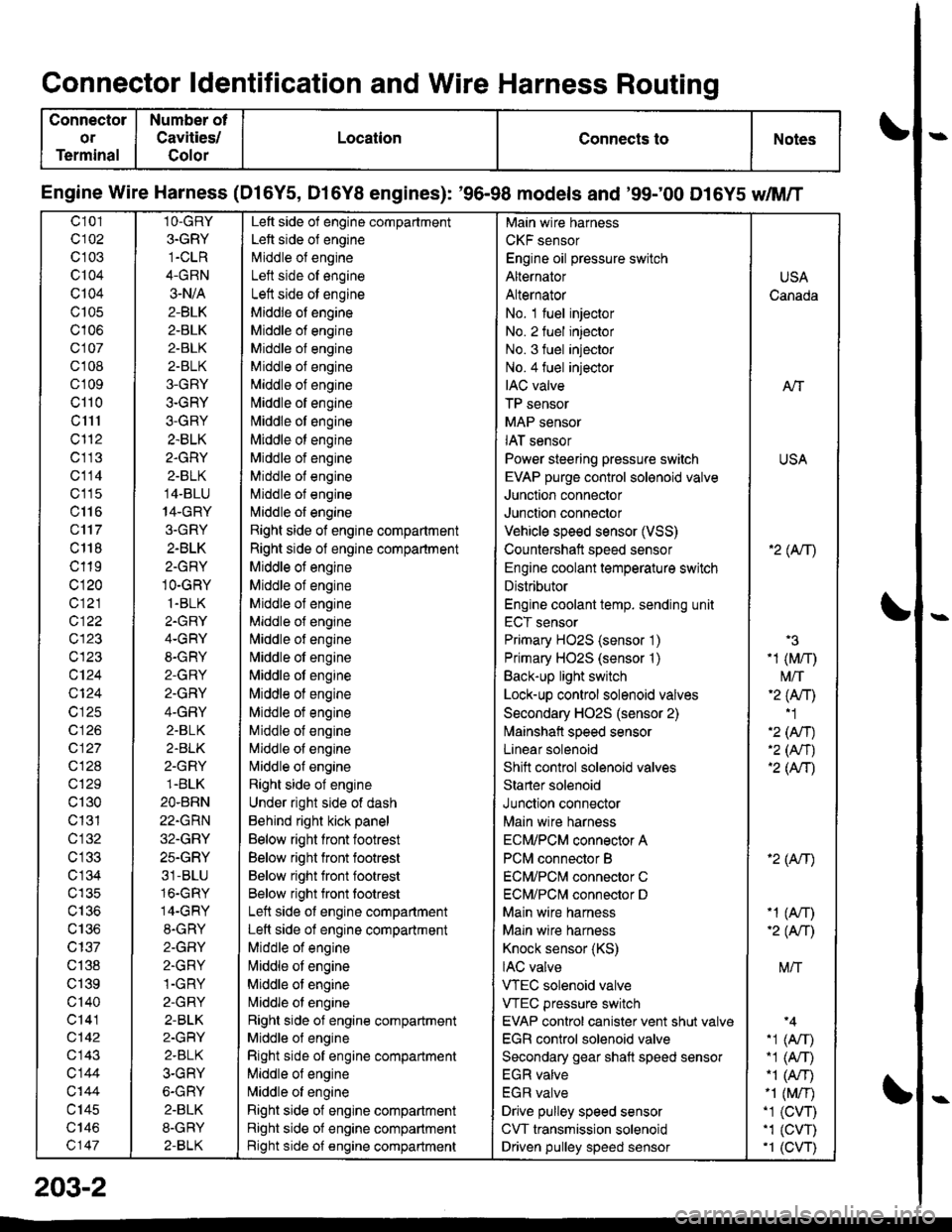
Connector ldentification and Wire Harness Routing
Connector
or
Terminal
Number ot
Cavities/
Golor
LocationConnects toNotes
Engine Wire Harness (Dl6Y5, D16Y8 engines): '96-98 models and '99;00 D16Y5 dM/T
c101
c102
c 103
c104
Q104
c105
c106
c107
cl 08
cl09
cl10
c1l1
cl'12
c113
c114
c'115
c116
c'117
c 118
c119
c120
c121
c122
c123
c123
c124
Q124
c125
c 126
c127
c128
c129
c130
c131
cl32
c 134
c135
c136
c137
c138
c139
c'140
c141
c142
c143
c144
c'|44
c145
c146
c147
1O-GRY
3.GRY
1-CLR
4-GRN
3-N/A
2-BLK
2-BLK
2-BLK
2-BLK
3-GRY
3-GRY
3-GRY
2.BLK
2.GRY
2-BLK
14-BLU
14-GRY
3.GRY
2-BLK
2-GRY
1O-GRY
1.BLK
2.GRY
4-GRY
8-GRY
2-GRY
2.GRY
4-GRY
2.BLK
2.BLK
2-GRY
1.BLK
2O.BRN
22.GRN
32.GRY
25.GRY
31-BLU
16.GRY
14-GRY
8.GRY
2-GFIY
2.GRY
1-GRY
2-GRY
2-BLK
2-GRY
2.BLK
3-GRY
6-GRY
2.BLK
8-GRY
2-BLK
Left side of engine compartment
Left side of engine
Middle of engineI att .i.la ^f an^i^6
Left side ot engine
Middle of engine
Middle of engine
Middle of engine
Middle of engine
Middle of engine
[,liddle of engine
Middle ot engine
Middle ot engine
Middle of engine
Middle of engine
Middle of engine
l\,liddle of engine
Right side of engine compartment
Right side of engine compartment
Middle ot engine
Middle of engine
Middle of engine
Middle of engine
l\,liddle of engine
Nliddle of engine
Middle ot engine
Middle of engine
Middle ot engine
Middle of engine
Middle of engine
Nliddle of engine
Right side of engine
Under right side of dash
Behind right kick panel
Below right front footrest
Below right front footrest
Below right front footrest
Below right front tootrest
Left side ot engine compartment
Left side of engine compartment
Middle of engine
liliddle ot engine
Middle of engine
Nriddle ol engine
Right side of engine compartment
Middle ol engine
Right side of engine compartment
Middle of engine
N,liddle of engine
Right side of engine compartment
Right side of engine compartment
Bight side of engine compartment
Main wire harness
CKF sensor
Engine oil pressure switch
Alternator
Alternator
No. 1 fuel injector
No. 2 fuel injector
No. 3 fuel injector
No.4 fuel injector
IAC valve
TP sensor
MAP sensor
IAT sensor
Power steering pressure switch
EVAP purge control sol€noid valve
Junction connector
Junction connector
Vehicle speed sensor (VSS)
Countershatt speed sensor
Engine coolant temperature switch
Distributor
Engine coolant temp. sending unit
ECT sensor
Primary HO2S (sensor '1)
Primary HO2S (sensor '1)
Back-up light switch
Lock-up control solenoid valves
Secondary HO2S (sensor 2)
lvlainshafl speed sensor
Lanear solenoid
Shift control solenoid valves
Starter solenoid
Junction connector
Main wire harness
ECM/PCM connector A
PCM connector B
ECM/PCNI connector C
ECM/PCl\,,| connector D
Main wire harness
Maln wire harness
Knock sensor (KS)
IAC valve
VTEC solenoid valve
VTEC pressure switch
EVAP control canister vent shut valv€
EGR control solenoid valve
Secondary gear shatt speed sensor
EGR valve
EGR valve
Drive pulley speed sensor
CVT transmission solenoid
Driven pulley speed sensor
USA
Canada
AlT
USA
'2( tr\
'3
-1 (M/r)
t\4/T'2 (Anl'1
'2 (An)'2 (Nr)'2 (AtT)
'2 (Atr)
-1 (An)-2( fi|
M/T
.1 (Arr).1 (A,T)"1 (A/r)-1 (M/r).1 (CVT),1 (cw)'1 (CVT)
203-2