Page 1014 of 2189
Transmission
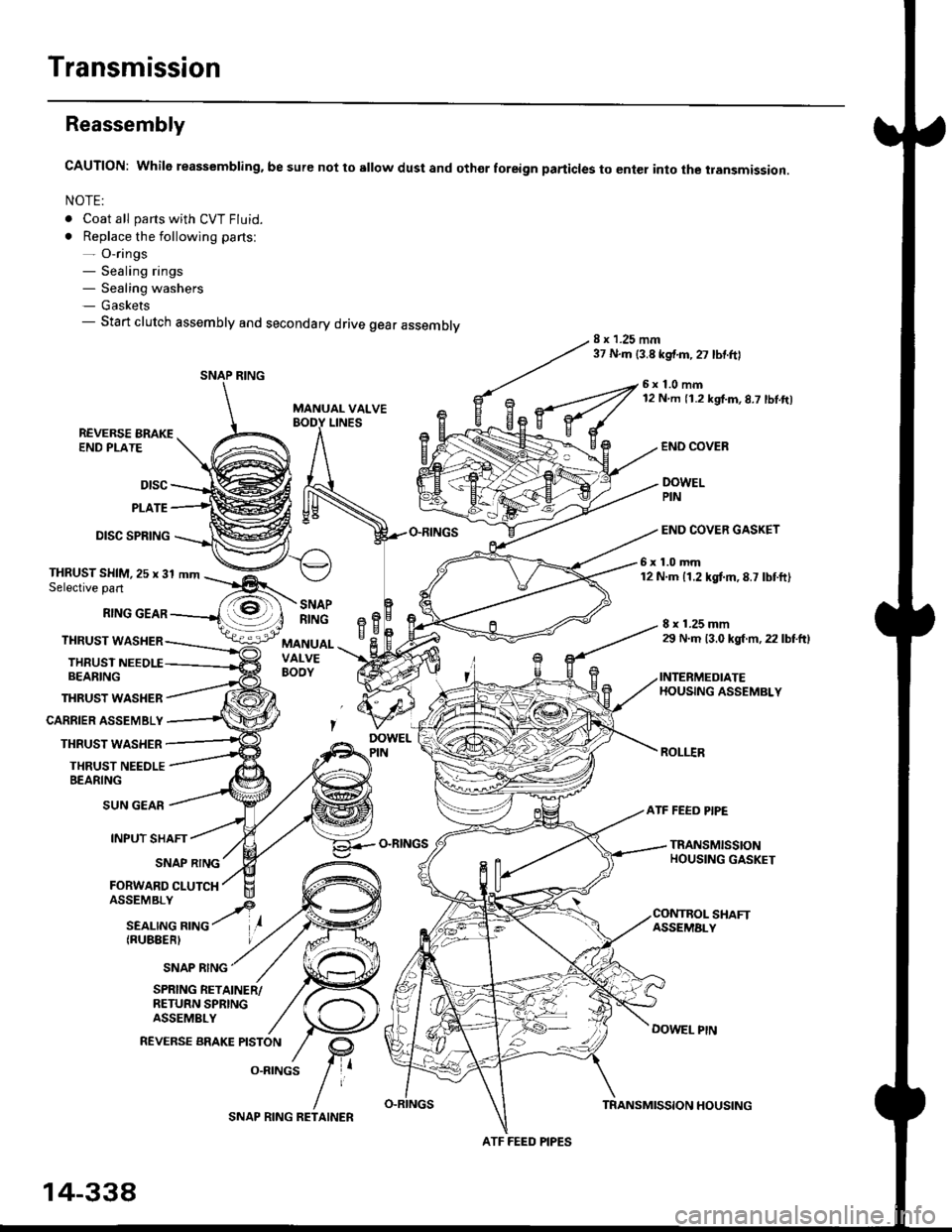
Reassembly
CAUTION: While reassembling. be sure not to sllow dust and othor foreign particles to enter into the transmission.
NOTE:
. Coat all parts with CVT Fluid.
. Replace the following parts:- O-rings- Sealing rings- Sealing washers- Gaskets- Start clutch assembly and secondary drive gear assembly8 x 1.25 mm37 N.m {3.8 kgf.m,27 lbtftl
MANUAL VALVE
6x1.0mm12 N m 11.2 kgf.m,8.7 lbl.ft)
LINESREVERSE BRAKEEND PLATE
Dtsc
PLATE
DISC SPRING
THRUST WASHER
CARRIER ASSEMBLY
THRUST WASHER
THRUST NEEDLEBEARING
END COVEB
DOWELPIN
END COVER GASKET
6x1.0mm12 N.m 11.2 kgtm,8.7 lbtft)THRUST SHIM,25 x 31 mmSelective part
RING GEAR
THRUST WASHER
THRUSTBEARING
8 x 1.25 mm29 N.m 13.0 kgl m, 22 lbtftl
INTERMEDIATEHOUSING ASSEMBLY
ROLI.IR
SNAPRINGeBH^cMANUALVALVEBOOY
SUN GEAR
INPUT SHAFT
(RUBEERI
ATF FEED PIPE
O-RINGSTRANSMISSIONHOUSING GASKETSNAP RING
FORWARD CLUTCH
SNAP RING
SHAFTASSEMALY
DOWEL PtN
SPRING RETAINER/RETURN SPRINGASSEMBLY
REVERSE BRAKE PISTON
O.RINGS
SNAP RING
ATF FEED PIPES
14-338
SNAP RING RETAINERTRANSMISSION HOUSING
Page 1015 of 2189
1.
7.
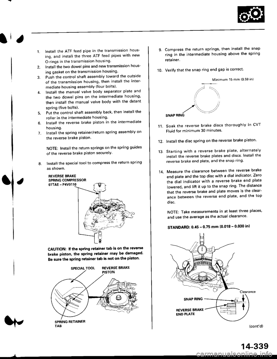
lnstall the ATF feed pipe in the transmission hous-
ing, and install the three ATF feed pipes with new
O-rings in the transmission housing,
Install the two dowel pins and new transmission hous-
ing gasket on the transmission housing.
Push the control shaft assembly toward the outside
of the transmission housing, then install the inter-
mediate housing assembly (four bolts).
lnstall the manual valve body separator plate and
the two dowel pins on the intermediate housing,
then install the rnanual valve body with the detent
spring (five bolts).
Put the control shaft assembly back, then install the
roller in the intermediate housing.
lnstall the reverse brake piston in the intermediate
housing.
Install the spring retainer/return spring assembly on
the reverse brake Piston.
NOTE: Installthe return springs on the spring guides
of the reverse brake piston securely
tnstall the special tool to compress the return spring
as shown.
REVERSE BRAKESPRING COMPRESSOR07TAE - P4V0110
6.
L
1
CAUTION: lf the spring retainer tab is on the reverse
brakc piston, the spring rstainer may be damaged'
Be sure the spring retainer tab is not on the piston'
rp
SPECIALTOOL REVERSEBRAKE
-^
14-339
10.
9.
14.
Compress the return springs, then install the snap
ring in the intermediate housing above the spring
retainer.
Verify that the snap ring end gap is correct'
Mini
/,,- '-t,,,,.
// \i/ ',r
'1 ,
.r' //'/. .-J?RINGSNAP
mum 15 mm 10.59 in)
Soak the reverse brake discs thoroughly in CVT
Fluid for minimum 30 minutes.
Installthe disc spring on the reverse brake piston'
Starting with a reverse brake plate, alternately
install the reverse brake plates and discs lnstall the
reverse brake end plate, and the snap ring'
Measure the clearance between the reverse brake
end plate and the top disc with a dial indicator' Zero
the dial indicator with a reverse brake end plate
lowered, and lift it up to the snap ring The distance
that the reverse brake and plate moves is the clear-
ance between the reverse end plate, and the top
disc.
NOTE: Take measurements in at least three places'
and use the average as the actual clearance'
STANDARD: 0.45 - 0.75 mm (0.018 - 0'030 in)
{cont'd)
11.
12.
13.
Page 1018 of 2189
Transmission
Reassembly (cont'd)
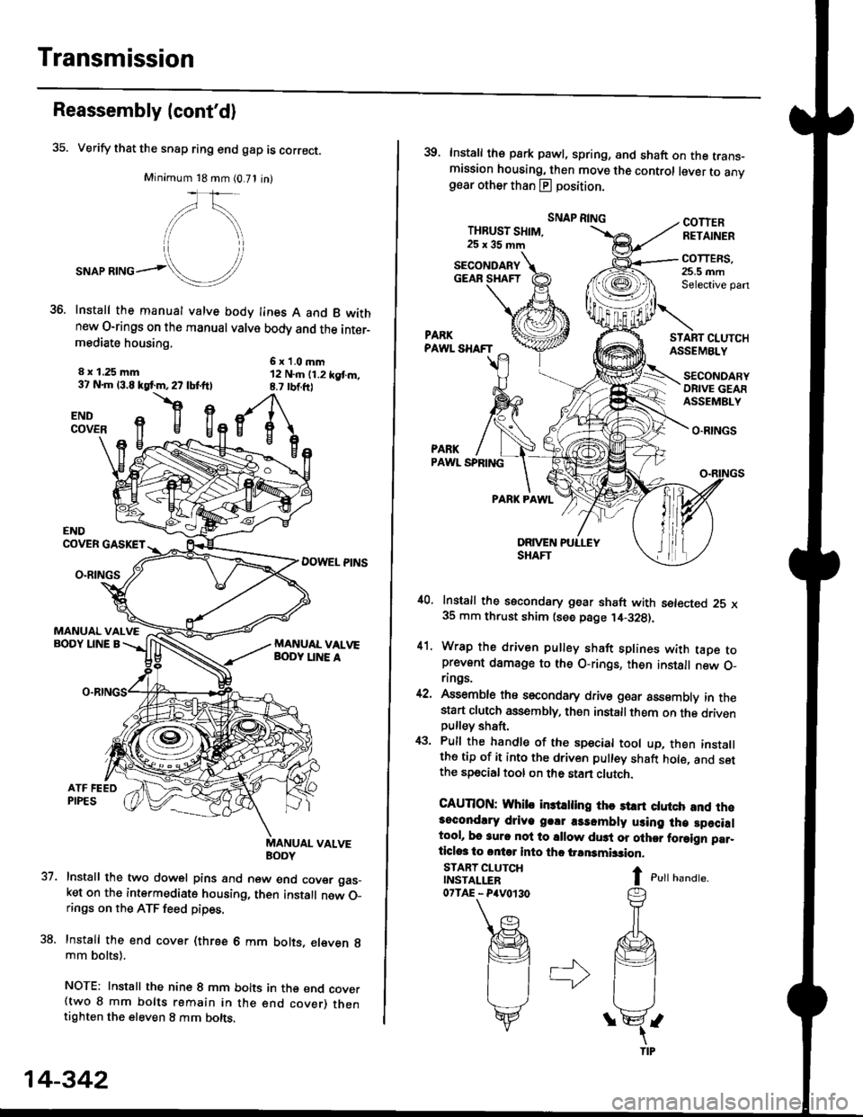
35. Verify that the snap ring end gap is correct.
Minimum 18 mm (0.71 in)
,/\,
."or**ol!/'
Install the manual valve body lines A and B wkhnew O-rings on the manual valve body and the inter-mediate housing.
6x1.0mm12 N..n (1.2 kgt m,8.7 rbtft)
8 x 1.25 mm37 N.m 13.8 kgf.m,27 lbf.ftl
flgENDCOVER
37.
ENDCOVER GASKET
DOWEL PINSO-RINGS
MANUAL VALVEBODY LINE A
uaNYuAL VALVE
Install the two dowel pins and new end cover gas_ket on the intermediate housing, then install new O_rings on the ATF feed pipes.
Install the end cover (three 6 mm bolts, eleven g
mm bolts).
NOTE: Install the nine 8 mm bolts in the end cover(two 8 mm bolts remain in the end cover) thentighten the eleven 8 mm bolts.
14-342
39. Install the park pawl, spring, and shaft on the trans-mission housing, then move the control lever to anvgear other than E position.
THBUST SHIM,25x35mm
SNAP RINGCOTTERRETAINER
COTTERS,25.5 mmSelective pan
START CI.UTCHASSEMBLY
O.RINGS
PARKPAWL SPRING
PARK PAWL
,10, Install the secondary gear shaft with setected 25 x35 mm thrust shim (see page ,14-328).
41. Wrap the driven pulley shaft splines with taDe toprevent damage to the O-rings, then install new O_rings.
42, Assemble ths secondary drive goar assembly in thestart clutch assembly, then installthem on the drivenpulley shaft,
43. Pull the handle of the special tool up, then installthe tip of it into the driven pulley shaft hole, and setthe special tool on the stan clutch.
CAUTION: Whib in3trling thc st rt ctutch and rh.3ocondlry driye g.!r a3sombly using lh€ specialtool, bo 3urc nol to sllow du3t or olher foraign par_ticlos to ontq into tho iransmbsion.
I c,rr r,unar".
SECONDARYGEAR SHAFT
START CLUTCHINSTALLER07TAE - P4V0r30
SECONDARYORIVE GEAFASSEMBLY
Page 1052 of 2189
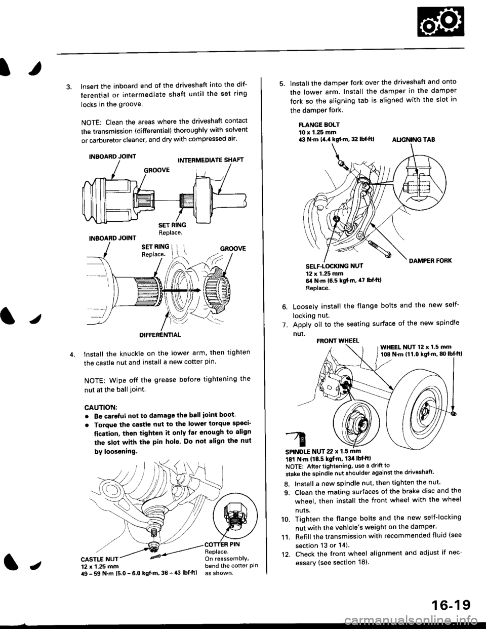
3. lnsert the inboard end of the driveshaft into the dif-
terential or intermediate shaft until the set ring
locks in the groove
NOTE: Clean the areas where the driveshaft contact
the transmission (differential) thoroughly with solvent
or carburetor cleaner, and dry with compressed air'
INBOARD JOINT
INBOARD JOINTReplace.
GROOVE
an
DIFFERENTIAL
lnstall the knuckie on the lower arm. then trghten
the castle nut and install a new cotter pin
NOTE: wipe off the grease before tightening the
nut at the ball ioint.
CAUTION:
. Be careful not to damago the ball ioint boot'
. Torque the castle nut to the lower torque sp€ci-
fication, thsn tighten it only far enough to align
the slot with th€ pin hol6. Do not align the nut
by loosening.
CASTLE NUT12 x 1 .25 mm
COTTER PINReplace.On reassemblY,bend the cotter pinJi$ - 59 N.m 15.0 - 6.0 kgl m,35 - 43 lbf ftl
16-19
5. lnstall the damper tork over the driveshaft and onto
the lower arm. Install the damper in the damper
fork so the aligning tab is aligned with the slot in
the damPer fork.
FLANGE BOLTl0 r 1.25 mmrit N.m t4.a kgf.m, 32 lbf.ft) AIIGN|NG TAB
1.
SELF-LOGKING NUT12 x 1.25 mm6,1N.m 16.5 kgi.m, a7 lbfftl
Replace.
Loosely install the flange bolts and the new self-
locking nut.
Apply oil to the seating surface of the new spindle
nut.
181 N m 118.5 kgt'm, 13il lbt'ftl
NOTE: Aftortightening, use a drift to
stake the spindle nut shoulder against the drivoshaft'
8. Install a new spindle nut, then tighten the nut'
9. Clean the mating surfaces ot the brake disc and the
wheel. then install the front wheel with the wheel
nuts.
10. Tighten the flange bolts and the new self-locking
nut with the vehicle's weight on the damper.
11. Refill the transmission with recommended fluid (see
section 13 or 14).'t2. Check the front wheel alignment and adjust if nec-
essary (see section 18),
FRONT WHEEL
SPINDLE NUT 22 x 1.5 mm
WHEEL NUT 12 x 1.5 mm108 N.m (11.0 kgl'm, g) lbl ftl
Page 1053 of 2189
Intermediate Shaft
Removal
Drain the transmission oil or fluid {see section 13 or
r 4).
Remove the left driveshaft (see page 16-3).
Remove the three dowel bolts.
OOWEL BOLTS'10 x 1.25 mm
Remove the intermediate shaft from the differential.
CAUTION: Hold the intermsdiate shaft horizontal
until it is clear of lhe dilterential to prevent damage
to the differential oil seal.
'1.
2.
3.
INTERMEDIATE SHAFT
16-20
Disassembly
NOTE: Be careful not to damage the metal rings on theintermediate shaft during disassembly.
1. Remove the set ring.
2. Remove the intermediate shaft outer seal from theDeaflng suppon.
3. Remove the external circlip,
Page 1054 of 2189
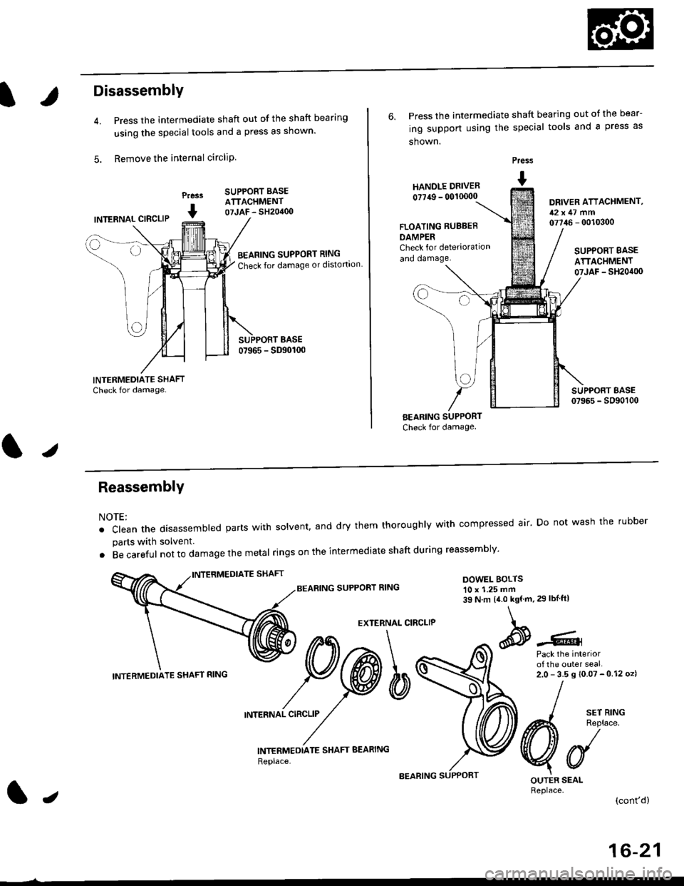
Disassembly
Press the intermediate shaft out of the shaft bearing
using the special tools and a press as shown.
Remove the internal circliP
Press
I
SUPPORT BASEATTACHMENT07JAF - SH20400INTERNAL CIBCLIP
BEARING SUPPORT RING
Check for damage or distortion
6. Press the intermediate shaft bearing out ot the bear-
ing support using the special tools and a press as
shown.
HANOLE DRIVER
0?749 - 00'�10000
Press
I
DRIVER ATTACHMENT,12x47 mm07746 - 0010300FLOATING RUBBEB
DAMPERCheck for deterioration
and oamage.SUPPORT BASE
ATTACHMENT07JAF _ SH20it00
BEARING SUPPORT
Check for damage
I sErR'NG
A4 Reolace
VUOUTER SEALReplace.(cont'd)
ReassemblY
NOTE:
. clean the disassembted parts with solvent, and dry them thoroughly with compressed air' Do not wash the rubber
parts with solvent.
. Becareful not to da mage the metal ringson the intermediate shaftduring reassembly'
BEARING SUPPORT RINGDOWEL BOLTS10 x 1.25 mm39 N.m 14.0 kgf.m,29 lbIftl
EXTERNAL CIRCLIP
Pack the interiorof the outer seal.2.0-35s10.07-012oz)
INTERNAL CIRCLIP
INTERMEDTATE SHAFT BEARING
Replace,
INTERMEDIATE SHAFT RING
lJ
16-21
Page 1055 of 2189
lntermediate Shaft
Reassembly (cont'd)
1. Press the intermediate shaft bearing into the bear-ing support using the special tools and a press asshown.
Prass
I
DRIVER ATTACHMENT,52x55mm07746 - 001 0(X)
Seat the internal circlip in the groove of the bearingsuppon.
Press the intermediate shaft into the shaft bearingusing the special tools and a press.
Praa.r
I
@---
LJ
INTERMEDIATE SHAFT
DRIVER ATTACHMENT,35 mm LD.
16-22
Seat the external circlip in the groove of the inter-mediate shaft.
Install the outer seal into the bearing support usingthe special tools as shown.
NOTE: Install the seal ftush with the bearing sup-port.
Pre$
t HANDr.r DRTVER- 0011r(x)0
Pack the Interiorof the ouler seal.2.0- 3.5 g {0.07 -0.12 ozl
OUTEN SEAL
Install the new set ringgroove.
ORIVER ATTACHMENT,52x55mm077i16 - 0010/O0
in the intermediate shaft
Page 1056 of 2189
lnstallation
1. lnsert the intermediate shaft assembly into the dif-
ferential.
CAUTION: Hold the intermodiate shaft horizontal
to prevent damag€ to the difterential oil seal'
NOTE: Clean the areas where the intermediate shaft
contacts the transmission (differential) thoroughly
with solvent or carburetor cleaner, and dry with com-
Dressed air,
2. Install the three dowel bolts, then tighten them'
DOWEL BOLTS10 x 1.25 mm39 N.m {i1.0 kgf'm, 29 lbf'ftl
lz
16-23