Page 195 of 2189

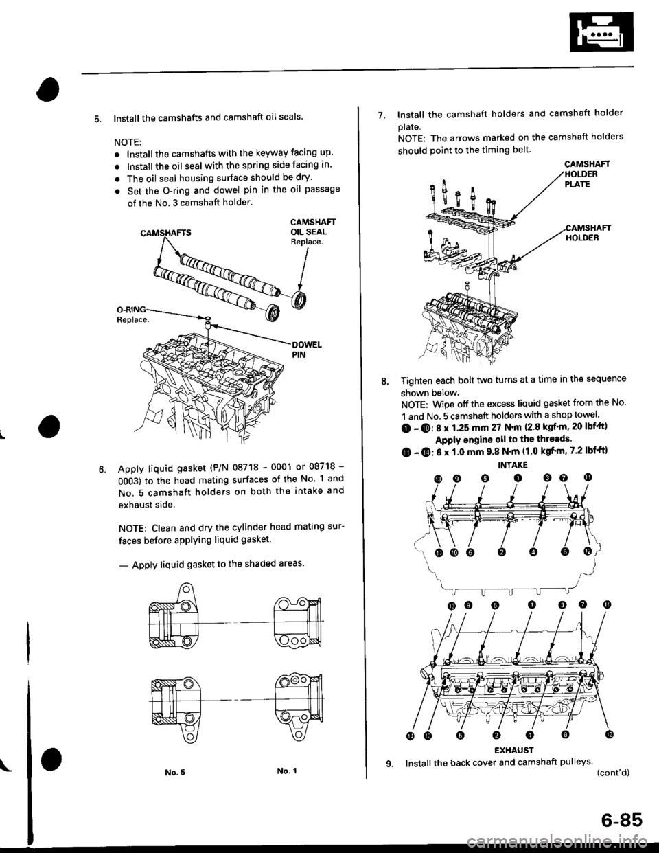
5. lnstall the camshafts and camshaft oil seals.
NOTE:
. lnstallthe camshafts with the keyway facing up.
. lnstall the oil seal withthespring side facing in.
. The oil seal housing surface should be dry'
. Set the O-ring and dowel pin in the oil passage
of the No, 3 camshaft holder'
CAMSHAFTOIL SEALReplace.
Apply liquid gasket (P/N 08718 - 0001 or 08718 -
0OO3) to the head mating surfaces of the No. 1 and
No. 5 camshaft holders on both the intake and
exhaust side.
NOTE: Clean and dry the cylinder head mating sur-
faces before applying liquid gasket.
- Apply liquid gasket to the shaded areas'
7- lnstall the camshaft holders and camshaft holder
plaIe.
NOTE: The arrows marked on the camshaft holders
should point to the timing belt.
Tighten each bolt two turns at a time in the sequence
shown below.
NOTE: Wipe off the excess liquid gasket from the No.
1 and No. 5 camshaft holders with a shop towel
(D - @: 8 x 1.25 mm 27 N.|n (2.8 ksf'm, 20 lbf'ft)
Apply ongine oil to the throads.
O - O: 6 x 1.0 mm 9.8 N'm (1.0 kgfrm, 7.2 lbf'ft)
INTAKE
(D o o o oo o
EXHAUST
lnstall the back cover and camshaft pulleys.
{cont'd)
oooo0o@
CAMSHAFT
6-85
Page 196 of 2189

Cylinder Head
Installation (cont'dl
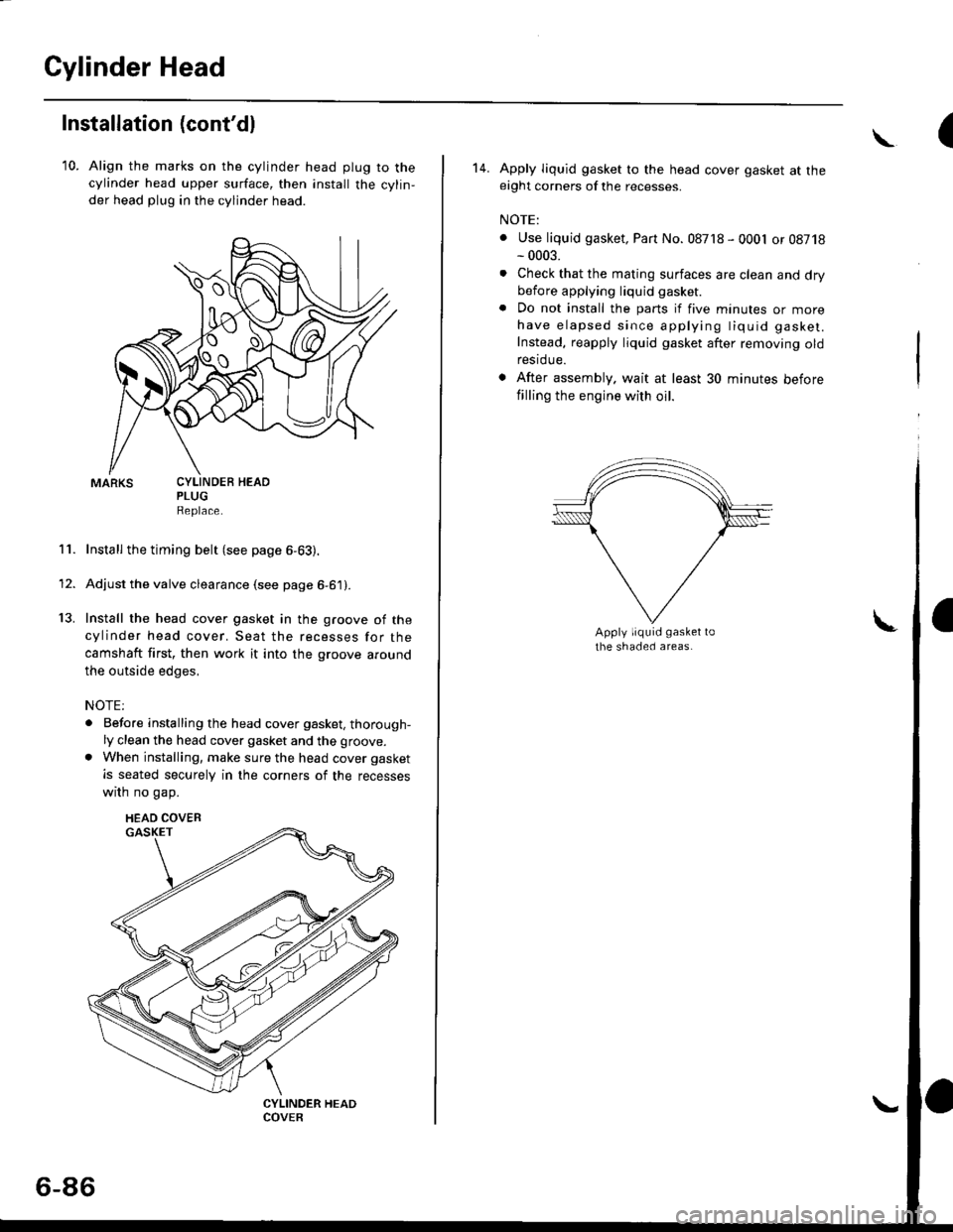
10. Align the marks on the cylinder head plug to thecylinder head upper surface, then install the cylin,
der head plug in the cylinder head.
PLUGReplace.
Install the timing belt (see page 6-63).
Adjust the valve clearance (see page 6-61).
Install the head cover gasket in the groove of the
cylinder head cover. Seat the recesses for the
camshaft first, then work it into the groove around
the outside edges,
NOTE:
. Before installing the head cover gasket, thorough-ly clean the head cover gasket and the groove.
. When installing, make sure the head cover gasket
is seated securely in the corners of the recesses
wrrn no gap.
11.
13.
1'
CYLINDEB HEAD
HEAD COVEB
6-86
(\
14. Apply liquid gasket to the head cover gasket at theeight corners of the recesses.
NOTE:
. Use liquid gasket, Part No. 08718 - 0001 or 08718- 0003.
. Check that the mating surfaces are clean and drybefore applying liquid gasket
. Do not install the parts if five minutes or morehave elapsed since applying tiquid gasket.
Instead, reapply liquid gasket after removing oldrestdue.
. After assembly. wait at least 30 minutes before
filling the engine with oil.
Page 197 of 2189
15. When installing the cylinder head cover, hold the
head cover gasket in the groove by placing your fin-
gers on the camshaft holder contacting surfaces
(toD of the semicircles).
Once the cylinder head cover is on the cylinder
head, slide the cover slightly back and forth to seat
the head cover gasket.
NOTE:
. Be{ore installing the cylinder head cover, clean
the cvlinder head contacting surfaces using a
shoP towel.
. Oo not touch the parts where liquid gasket was
applied.
. Replace any washer taht is damaged or deter'o-
rated.
t
\
6-A7
16. Tighten the nuts in two or three steps. In the final
step, tighten all nuts, in sequence, to 9 8 N'm {1 0
kgf.m, 7.2 lbf.ft).
NOTE: After assembly, wait at least 30 minutes
before filling the engine with oil.
After installing, check that all tubes' hoses and con-
nectors are installed correctly.17.
Page 461 of 2189

ldle Control System
ldle ControlSystem
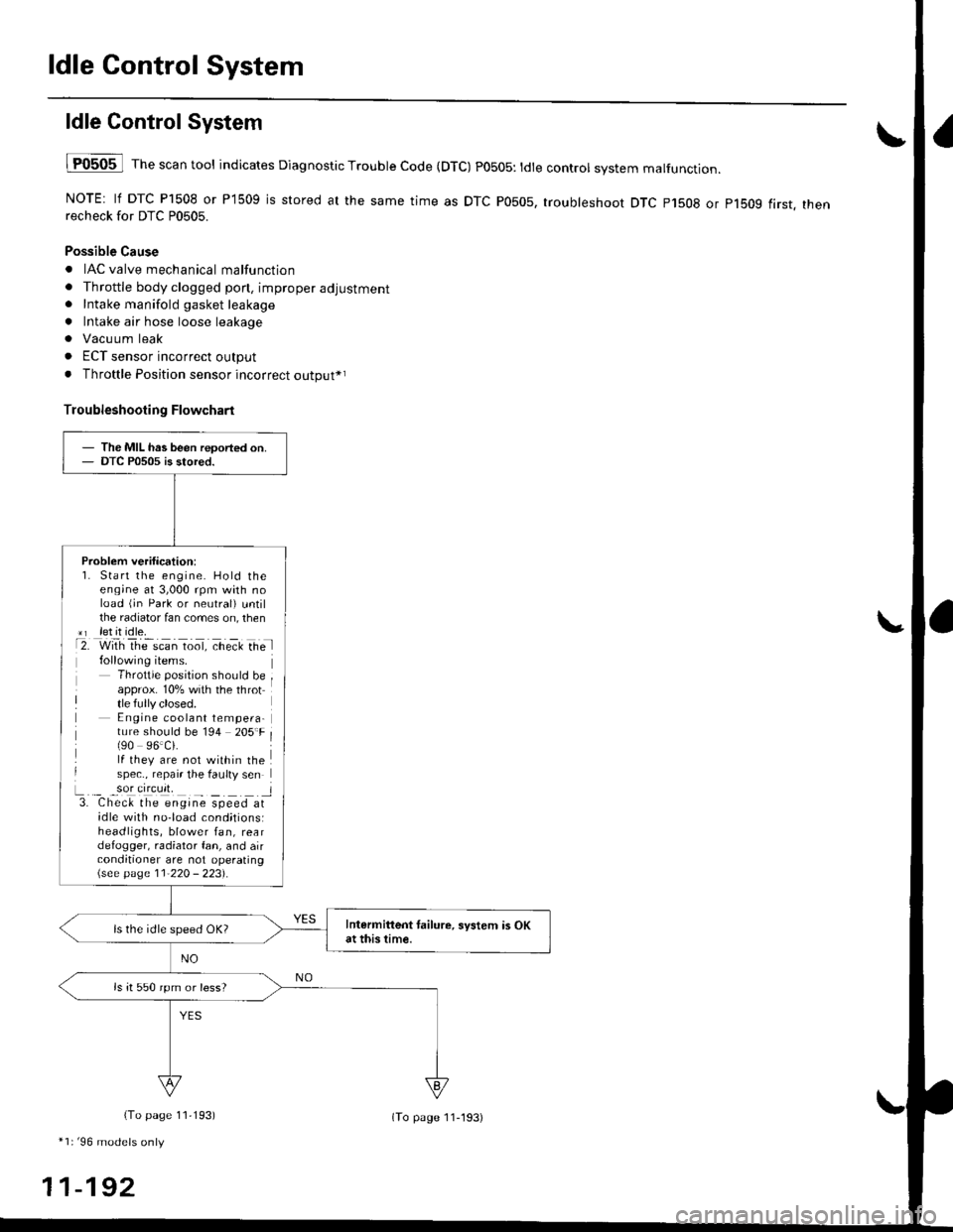
lF0505 l Th" """n tool indicates Diagnostic Trouble Code (DTC) PO5O5: tdte controt system malfunction.
NOTE: lf DTC P1508 or P1509 is stored at the same time as DTC P0505, troubleshoot DTC p1508 or p1bog first. thenrecheck for DTC P0505.
Possible Cause
. IAC valve mechanical malfunction
. Throttle body clogged pon, improper adjustment. Intake manifold gasket leakage
. Intake air hose loose leakage
. Vacu um leak
. ECT sensor incorrect output
. Throttle Position sensor incorrect output*r
Troubleshooting Flowchart
The MIL has been reoorted on.DTC P0505 is stored.
Problem verification:1. Start the engine. Hold theeng;ne at 3,000 rpm with noload (jn Park or neutral) untilthe radiator fan comes on, then*r let it idle.t2. with rhe scan toot, ct'eit Ge l
Throttle position should beapprox. 10% with the throttle fully closed.E ngine coolant tempera-ture should be 194 205'F(90 96.Ci.lf they are not within thespec., repair the faulty sen
L._ _9oI9[cr]41 l3. Chec& the engine speed atidle with no-load cond;tionsiheadlights, blower fan, reardefogger, radiator fan, and airconditioner are not operating\see page l1-22O - 223).
Intermittent tailure, system is OKat this time.ls the idle speed OK?
ls it 550 rpm or less?
(To page 11,193)
*1r'96 models only
11-192
(To page ll-193)
Page 857 of 2189

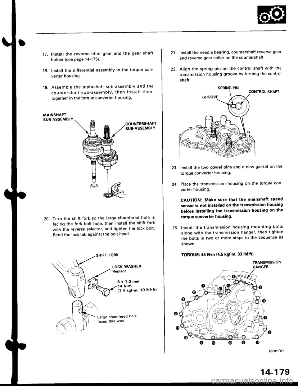
17.
18.
19.
lnstall the reverse idler gear and the gear shaft
holder (see page 14-175).
lnstall the differential assembly in the torque con-
verter housing.
Assemble the mainshaft sub-assembly and the
countershaft sub-assembly, then install them
together in the torque converter houslng
MAINSHAFTSUB-ASSEMBLY
20,
COUNTERSHAFTSUB.ASSEMBLY
Turn the shift fork so the large chamfered hole is
tacing the fork bolt hole, then install the shift fork
with the reverse selector, and tighten the lock bolt'
Bend the lock tab against the bolt head
SHIFT FORK
LOCK WASHERReplace.
6 x 1.0 mm4 N.m('l.4 kgl'm, 1O lbt'ft)
Large chamtered hole
21.
22.
lnstall the needle bearing, countershaft reverse gear
and reverse gear collar on the countershaft.
Align the spring pin on the control shaft with the
transmission housing groove by turning the control
shaft.
CONTROL SHAFT
Install the two dowel pins and a new gasket on the
torque converter housing.
Place the transmission housing on the torque con-
verter housing.
CAUTION: Make sure that lhe mainshaft speed
sensor is not installed on the transmission housing
before installing the transmission housing on the
torque conv€rter housing.
lnstall the transmission housing mounting bolts
along with the transmission hanger, then tighten
the bolts in two or more steps in the sequence as
shown.
TOROUE: ,l,t N'm l{.5 kgf'm, 33 lbf'ft}
TRANSMISSIONHANGER
24.
o
(cont'di
SPRING PIN
14-179