1999 HONDA CIVIC coolant hose
[x] Cancel search: coolant hosePage 289 of 2189
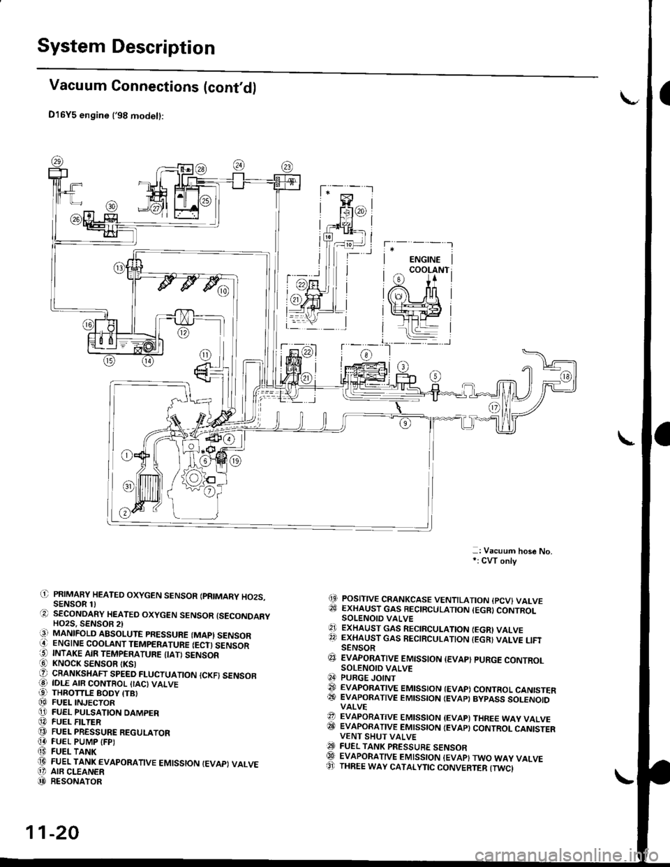
System Description
Vacuum Connections (cont'd)
D16Y5 engine ('98 modet):
-: Vacuum hose No,*: CW only
(9 POSITIVE CRANKCASE VENTILATION {PCV} VALVE?!J EXHAUST GAS BECIRCULATION (EGR}CONTROLSOLENOIO VALVE'1 ExHAUST GAs RECIRCULATIoN IEGRI VALVE22 EXHAUST GAS RECIRCULATION {EGR} VALVE LIFISENSOR€J EvApoRATtvE EMtsstoN {EvAp} puRGE coNTRoLSOLENOID VALVEq4 PURGE JOINT@ EVAPoRATIVE EMIssIoN {EVAP) coNTRoL CANISTER@� EVAPORATIVE EMISSION IEVAP} BYPASS SOLENOIDVALVE?? EVAPORATIVE EMISSION {EVAP) THREE WAY VALVEITII EVAPORATIVE EMISSION IEVAP} CONTROL CANISTERVENT SHUT VALVEO FUEL TANK PRESSURE sENsoRQlI EVAPORATIVE EMISSION {EVAP}TWO WAY VALVE8' THREE WAY CATALYTIC CONVERTER {TWCI
il) PRIMAFY HEATED OXYGEN SENSOR IPRIMARY HO2S.SENSOR 1)O SECoNDARY HEATEo oxYGEN sENsoR {sEcoNDARYHO2S. SENSOB 2)iq] MANIFOLD ABSOLUTE PRESSURE (MAPI SENSORO ENGINE COOLANT TEMPERATURE IECT) SENSOR5 INTAKE AIR TEMPERATURE {IATI SENSOR! KNOCK SENSOR tKSlO CRANKSHAFT SPEED FLUCTUATIoN {cKF) sENsoFO IDLE AIR coNTRoL {IAc) vALvE99 THROTTLE BODY ITBI@ FUEL INJECToRO FUEL PULSATION DAMPER@ FUEL F -TER@ FUEL PRESSURE REGULAToR[4 FUEL PUMP IFPI(9 FUEL TANK(D FUEL TANK EVAPoRATIVE EMIssIoN IEVAPI VALVEO' AIR CLEANER(D RESoNAToR
11-20
Page 355 of 2189
Troubleshooting
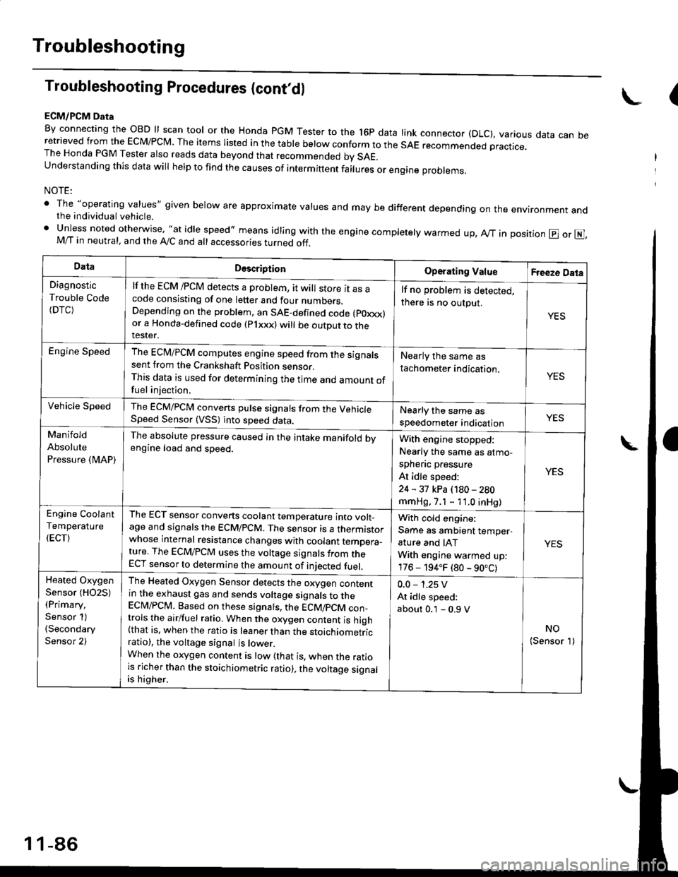
Troubleshooting Procedures (cont,dl
ECM/PCM Data
By connecting the OBD ll scan tool or the Honda pGM Tester to the l6p data link connector (DLC), various data can beretrieved from the EcM/PcM. The items Iisted in the table below conform to the sAE recommended practice.The Honda PGM Tester also reads data beyond that recommended bv SAE.understanding this data wil help to find the causes of intermittent fairures or engine probrems,
NOTE:
' The "operating values" given below are approximate values and may be different depending on the environment andthe individual vehicle.. Unless noted otherwise, "at idle speed,, means idling with the engine completely warmed up, Ay'T in position @ or E],M/T in neutral, and the Ay'C and all accessories turned off.
(
DataDescriptionOperating ValueFreeze Data
Diagnostic
Trouble Code(DTC)
lf the ECM /PCM detects a problem, it will store it as acode consisting of one letter and four numbers.Depending on the problem, an SAE-defined code (poxxx)or a Honda-defined code (Plxxx) will be outDut to therester.
lf no problem is detected,
there is no output.
YES
Engine SpeedThe ECM/PCM computes engine speed from the signalssent from the Crankshaft Position sensor.This data is used for determining the time and amount offuel injection,
Nearly the same as
tachometer indication.YES
Vehicle SpeedThe ECM/PCM converts pulse signals from the VehicleSpeed Sensor (VSS) into speed data.Nearly the same as
speedometer indicationYES
Manifold
Absolute
Pressure {MAP)
The absolute pressure caused in the intake manifold bvengine load and speed.With engine stopped:
Nearly the same as atmo-
spheflc pressure
At idle speed:
24 - 31 kPa (180 - 280
mmHg, 7.1 - 11.0 inHg)
YES
Engine Coolant
Temperature
(ECT)
The ECT sensor converts coolant temperature into volt_age and signals the ECM/PCM. The sensor is a thermistorwhose internal resistance changes with coolant temDera_ture. The ECM/PCM uses the voltage signals from theECT sensor to determine the amount of iniected fuel.
With cold engine:
Same as ambient temper,
ature and IAT
With engine warmed up:
176 - 194.F (80 - 90.C)
YES
Heated Oxygen
Sensor {HO2S)(Primary,
Sensor 1)(Secondary
Sensor 2)
The Heated Oxygen Sensor detects the oxygen contentin the exhaust gas and sends voltage signals to theECI\4/PCM. Based on these signats, the ECM/pCM con_trols the airlfuel ratio. When the oxygen content is high(that is, when the ratio is leaner than the stoichiometricratio), the voltage signal is lower.When the oxygen content is low (that is, when the ratiois richer than the stoichiometric ratio), the voltage signalis higher.
0.0 - 1.25 V
At idle speed:
about 0.1 - 0.9 V
NO(Sensor 1)
1 1-86
Page 397 of 2189
PGM-FI System
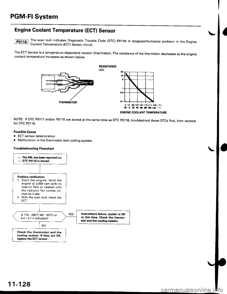
Engine Coolant Temperature (ECTI Sensor
The scan tool indicates Diagnostic Trouble code (DTC) P0116; A range/performance problem in the EngrneCoolant Temperature (ECT) Sensor circuit.
The ECT Sensor is a temperature dependant resistor (thermistor). The resistance of the thermistor decreases as the enginecoolant temperature increases as shown oetow.
RESISTANCE(ko)
NOTE: lf DTC P0117 and/or P01'18 are stored at the same time as DTCfor DTC P0116.
Possible Cause
. ECT sensor deterioration. Malfunction in the thermostat and cooling system
Troubleshooting Flowchart
-a 32 68 r0a la0l?6 2t2 2481'rr-20 o 20 ao o D r@ Il, r'c)
ENGINE COOLANT IEMPERATURE
P0116, troubleshoot those DTCS first. then recheck
11-128
THERMISTOR
- The MIL has bogn reported on.- DTC P0116 is stored.
Problem verification:1. Start the engine. Hotd theengine at 3,000 rpm with noload (in Park or neutral) untilthe radiator fan comes on,then let it idle.2. With the scan tool, check the
Intermiftent lailure. system is OKai thi. time. Ch.ck the thc.mo-stat 6nd thc cooling system.
is 176 200'F {80 - 93'C)or0.0-0.TVindicated?
Check the thermostat and thecooling system. ll they als OK,raplace the ECT sensor.
Page 460 of 2189
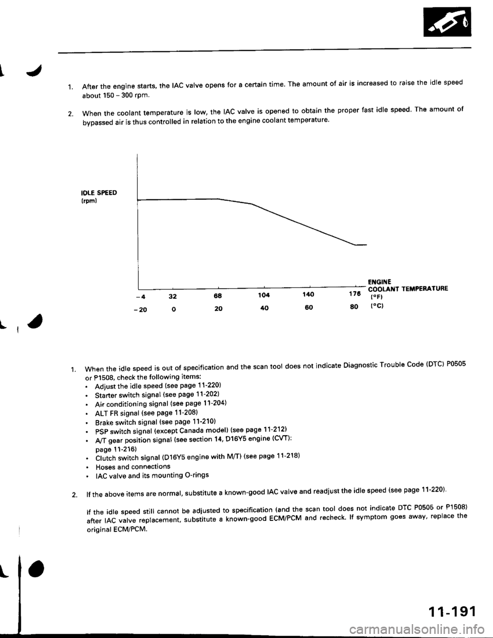
1.After the engine starts, the lAc valve opens for a certain time. The amount of air is increased to raise the idle speed
about 150 - 300 rpm.
When the coolant temperature is tow, the IAC valve is opened to obtain the proper fast idle speed. The amount of
bypassed air is thus controlled in relation to the engine coolant temperature'
IOLE SPEED
lrpml
176
80
ENGI ECOOLANI TEMPERATURE
t" Fl
toc)
ll
't.Whentheid|espeedisoutofspeciiicationandthescantoo|doesnotindicateDiagnosticTroub|ecode(DTc)P0505
or P1508. check the following items:
. Adiust the idle speed {see page 11-220}
. Starter switch signal (see page 11-202)
. Air conditioning signal (see page l1-204)
. ALT FR signal (see Page 11-2081
' Brake switch signal (see page 11-210)
. PSP switch signal (excapt Canada model) (see page 11-212)
. A,/T gear position signal {see section 14, Dl6Y5 engine (CVT):
page 11-216). Clutch switch signal (D16Y5 engine with M/T) (see page 11-218)
. Hoses and connections
' IAC valve and its mounting O-rings
lf the above items are normal, substitute a known-good IAC valve and readjust the idle speed (see page 11-220)
|ftheid|espeedsti||cannotbeadjustedtospecification(andthescantoo|doesnotindicateDTcP0505orP]50S)
after IAC valve replacement. substitute a known-good ECM/PCM and recheck. lf symptom goes away, replace the
original ECM/PCM.
Page 461 of 2189
ldle Control System
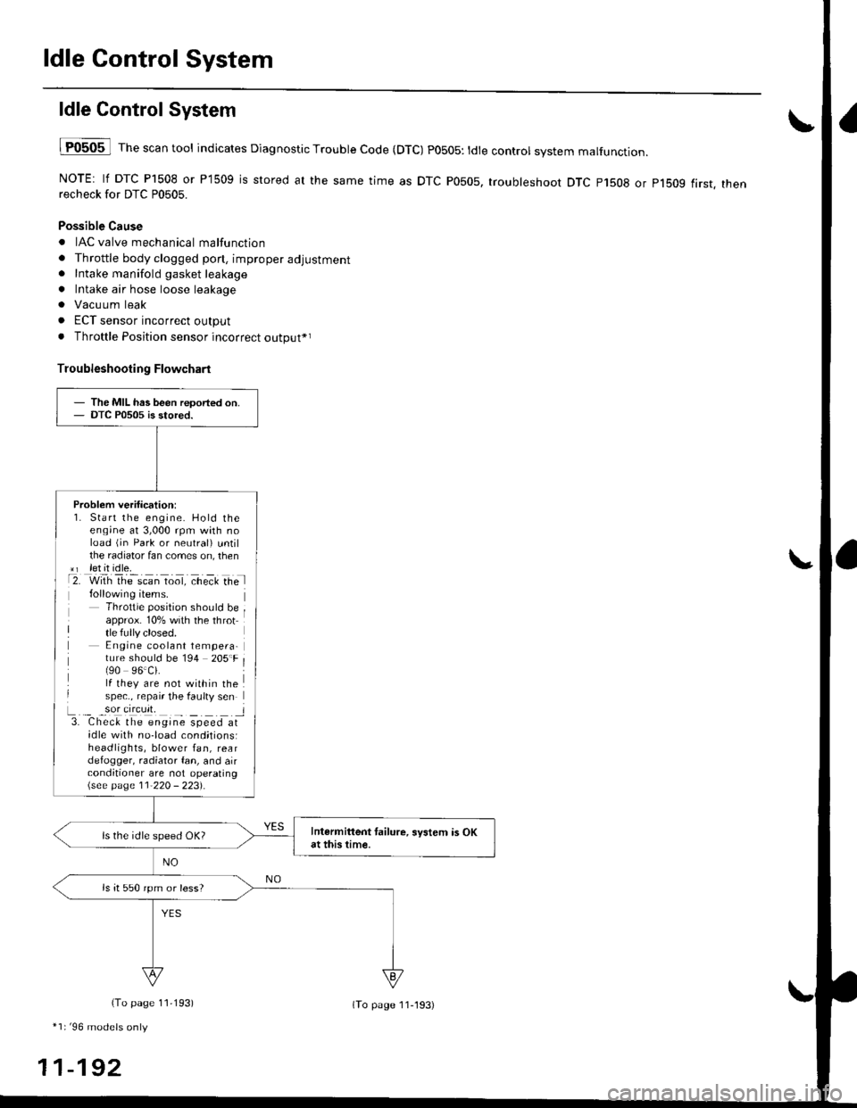
ldle ControlSystem
lF0505 l Th" """n tool indicates Diagnostic Trouble Code (DTC) PO5O5: tdte controt system malfunction.
NOTE: lf DTC P1508 or P1509 is stored at the same time as DTC P0505, troubleshoot DTC p1508 or p1bog first. thenrecheck for DTC P0505.
Possible Cause
. IAC valve mechanical malfunction
. Throttle body clogged pon, improper adjustment. Intake manifold gasket leakage
. Intake air hose loose leakage
. Vacu um leak
. ECT sensor incorrect output
. Throttle Position sensor incorrect output*r
Troubleshooting Flowchart
The MIL has been reoorted on.DTC P0505 is stored.
Problem verification:1. Start the engine. Hold theeng;ne at 3,000 rpm with noload (jn Park or neutral) untilthe radiator fan comes on, then*r let it idle.t2. with rhe scan toot, ct'eit Ge l
Throttle position should beapprox. 10% with the throttle fully closed.E ngine coolant tempera-ture should be 194 205'F(90 96.Ci.lf they are not within thespec., repair the faulty sen
L._ _9oI9[cr]41 l3. Chec& the engine speed atidle with no-load cond;tionsiheadlights, blower fan, reardefogger, radiator fan, and airconditioner are not operating\see page l1-22O - 223).
Intermittent tailure, system is OKat this time.ls the idle speed OK?
ls it 550 rpm or less?
(To page 11,193)
*1r'96 models only
11-192
(To page ll-193)
Page 520 of 2189
\J
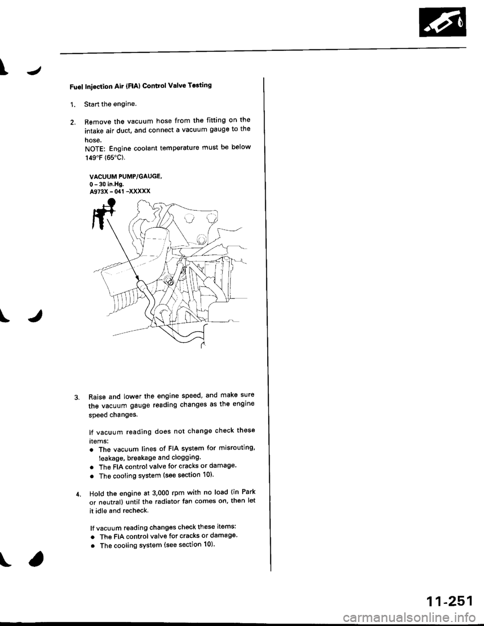
Fuol Iniection Air {FlA) Contlol Valve T$ting
1. Start the engine.
2. Remove the vacuum hose from the fitting on the
intake air duct, and connect a vacuum gauge to the
nose.
NOTE: Engine coolant temperature must be below
149"F (65"C).
VACUUM PUMP/GAUGE,
0-30 in.Hg.A973X - 041 -XXXXX
Raise and lower the engine speed, and make sure
the vacuum gauge reading changes as the engine
speed changes.
lf vacuum reading does not change check these
rtems:
. The vacuum lines of FIA system for misrouting,
leakage, breakage and clogging.
. The FIA controt valve for cracks or damage
. The cooling system (see section 10).
Hold the engine at 3,OOO rpm with no load (in Park
or neutral) until the radiator fan comes on, th€n let
it idle and recheck.
lf vacuum reading changes check these items:
a The FIA control valve for cracks or damage.
. The cooling system (see section 10).
11-251
Page 553 of 2189

Emission Control System
Evaporative Emission (EVAPI Controls (cont'dl
1
EVAP CONTROLCANISTER VENT SHUTVALVE 2P CONNECTOR IC141}
lltrt+ rcl
o) (8LK/YErl
I
temale terminalsWire side ot
ECM/PCM CONNECTOR A (32PI
VSV ILT GRN/WHT}
'l'
Wiro side of lemaletgrminals
VACUUMPUMP/GAUGE,0 - 30 in.Hg4973X -
041 - XXXXX
(From page 1l-283)
{To page 1l-285}
Check the vacuum whon cold:1. Disconnect the vacuum hoseshown from the EVAP controlcanrster and connect a vacuumgauge to the hose,2. Start the engine and allow itto idle.NOTE: Engine coolant tem-perature must be below 154oF(68'C) or lVC switch OFF.3. Ouickly raise the engine speedto 3,000 rpm.
(From page l1-283)
Check for an open in tho wire(lGl line):1. Turn the ignition switch OFF.2. Disconnect the 2P connectorlrom the EVAP control canis-ter vent shut valve.3. Turn the ignition switch ON (ll).4. Measure voltage between theEVAP controlcanister vent shutvalve 2P connector terminalNo. 2 and body ground.
Repair open in the wire betwe€nthe EVAP control c.ni3tei ventshut valve and th6 No. 15 ALTER-NATOR SP SENSOR 17.5 Al fuse.
Cfisck tor an opon in the wire (VSVline):1. Turn the ignition switch OFF.2. Beconnect the 2P connectorto the EVAP control canistervent shut valve.3. Turn the ignition switch ON (ll).4. Measure voltage betweenECM/PCM connector termi-nals A29 and Al0.
Rep.ir open in the wire betwoonthe EVAP control canister ventshut valve and th€ ECM/PCMtA29t.
ls there battery voltage?
Replace th6 EVAP control canis-ter vent 3hut valve.
PGT (BLKI
:lI23l'ltl'l lelsl ro Ir I1213t6€lnltlr@/lzzl zs f il
25
11-284
Page 558 of 2189

\
EVAP CONTROLCANISTER VENT SHUTVALVE 2P CONNECTOR IC141I
Wire side of temale terminals
ECM,/PCM CONNECTORS
tG1IBLK/WHT}
A973X -
0/r1 - XXXXX
Wire side of femaletermrnats
\
?,T-t
fl
VACUUMPUMP/GAUGE, 0 -30 in.Hg
\(cont'd)
11-289
{From page l1 288}
{To page 11-290)
Ch€ck the vac[um when cold:1, Disconnect the vacuum hoseshown from the EVAP controlcanister and connect a vacuumgauge to the hose.2. Start the engine and allow it
to idle.NOTEi Engine coolant temperature must be below 154"F(68'C) or Ay'C switch OFF.3. Ouickly raise the engine speedto 3,000 rpm.
(From page 11-288)
Check for an open in tha wire(lGt linol:1. Turn the ignition switch OFF.2. Disconnect the 2P connectorfrom the EVAP control canis-ter vent shut valve.3. Turn the ignition switch ON lll).4. Measure voltage between theEVAP control canister vent shut
valve 2P connector terminalNo.2 and bodyground.
Repair open in the wire betweenthe EVAP control canister ventshut valve .nd the No. 15 ALTER-NATOR SP SENSOR {7.5 A)fu3e.
ls there battery voltage?
Ch€d( for an op€n in the wiie IVSVlinel:1. Turn the ignition switch OFF.
2. R€connect the 2P connectorto the EVAP control canistervent shut valve,3. Turn the ignition switch ON (ll).
4. Measure vo ltage betweenECM/PCM connector termi-nals A4 and 82.
Repair open in the wire bctweenthe EVAP control canistor ventshut valve and lhe ECM/PCM{44t.
ls there battery voltage?
Rcolaco tho EVAP control canis.t6r vent shut valvo.
a t32P)
-