1999 HONDA CIVIC brake switch
[x] Cancel search: brake switchPage 445 of 2189

PGM-FI System
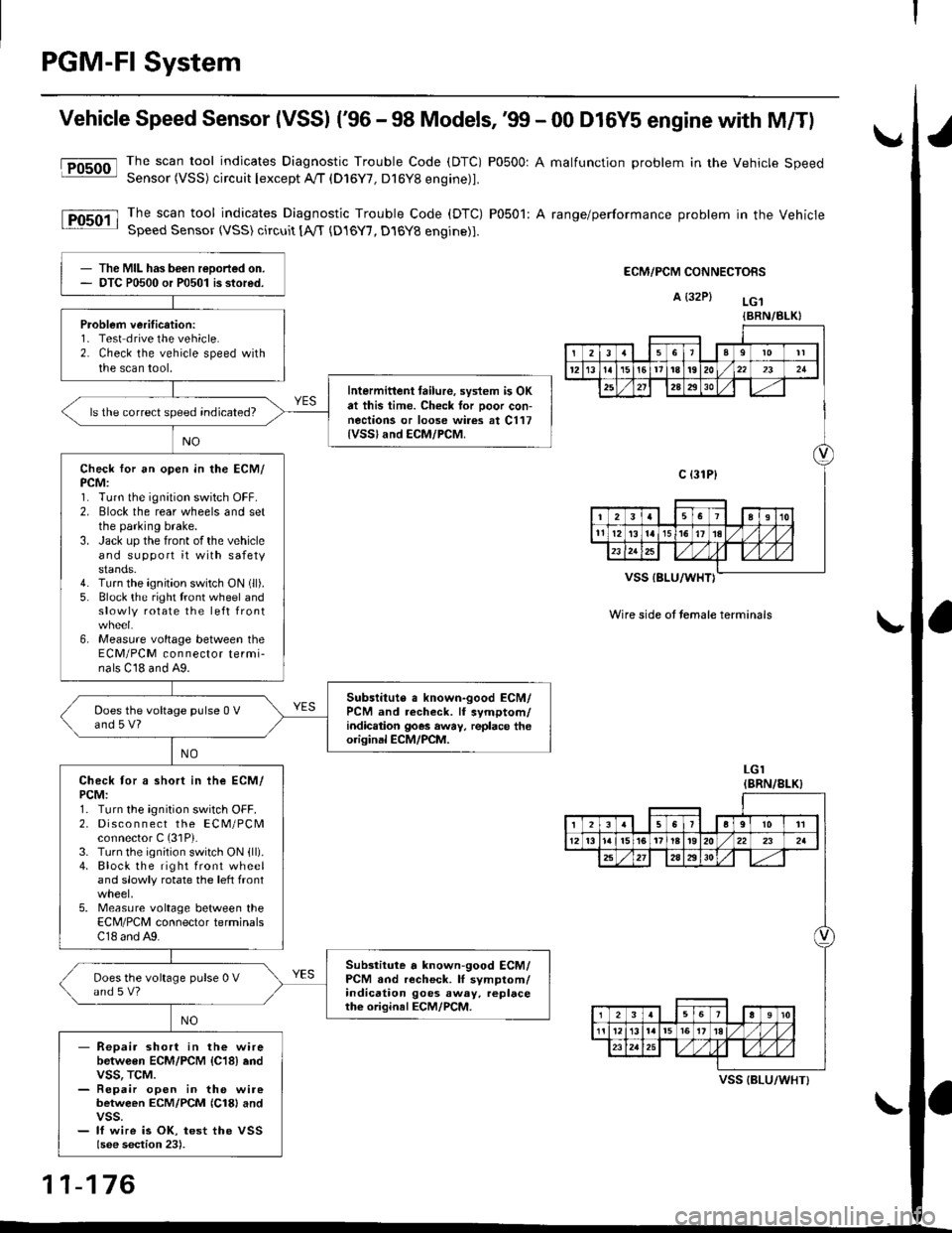
Vehicle Speed Sensor (VSSI ('96 - 98 Models,'99 - 00 D16Y5 engine with M/Tl
@The scan tool indicates Diagnostic Trouble Code (DTC) P0500: A malfunction problem in the Vehicle SpeedSensor (VSS) circuit Iexcept A!/T (D16Y7, D16Y8 engine)1.
The scan tool indicates Diagnostic Trouble Code (DTC) P0501: A range/performance problem in the VehicleSpeed Sensor (VSS) circuit [A,rT {D16Y7, D16Y8 engine)].
ECM/PCM CONNECTORS
A {32P} LG.t
VSS IBLU/WHT}
Wire side ot temale terminals
LGI(BRN/8LK}
The MIL has been reDorted on.DTC P0500 or P0501 is stored.
Problem verification:1- Test drive the vehicle.2. Check the vehicle speed withthe scan tool.
Intermittent tailure, system is OKat this time. Check tor Door con-nections or loose wires at C117{VSSland ECM/PCM.
ls the correct speed indicated?
Check for an open in the ECM/PCM:1. Turn the ignition switch OFF.2. Elock the rear wheels and setthe parking brake.3. Jack up the front of the vehicleand support it with safetystands.4. Turn the ignition switch ON (ll).
5. Block the right tront wheel andslowly rotate the left front
6, Measure voltage between theECM/PCM connector termi-nals C18 and A9.
Subslitute a known-good ECM/PCM and recheck. lf symptom/indic.tion goes away, replace theorisinal ECM/PCM.
Does the voltage pulse 0 Vand 5 V?
Check tor a short in ihe ECM/PCM:1. Turn the ignition switch OFF.2. Disco n n ect the ECM/PCMconnector C (31P).
3. Turn the ignition switch ON {ll).4. Block the right front wheeland slowly rotate the left front
5. Measure voltage between theECM/PCM connector terminalsC18 and A9.
Substitute a known-good ECM/PCM and recheck. lI symptom/indication goes away. replacethe original ECM/PCM.
Does the voltage pulse 0 Vand s V?
- Repair short in the wirebetwGen ECM/PCM {C18} endvss, TcM.- Repair open in the wirebetween ECM/PCM {Cl8} andvss.- lf wire is OK, test the VSSlsee section 23).
{BRN/BLK}
239l0lt
121611t8t9202321
2A2930
c {31P}
I38191o
tl12ialr5i6l10./
I2356a9l011
12l3l5t61tl8t920222a
27202930
12910
t2l13l.l7I l,/ 1,/231r.lslt., ),rlL
VSS {BLU/WHT}
11-176
Page 446 of 2189

fFosoo-l
lFosoil
Vehicle Speed Sensor (VSS) ('99 - 00 Models except Dl6Y5 engine with M/T)
Thescantoo|indicatesDiagnosticTroub|ecode(DTc)Po5o0:Ama|functionproblemintheVehic|espeed
Sensor (VSS) circuit lexcept A//T (D16Y/, D16Y8 engine)l'
Thescantoo|indicatesDiagnost|cTroub|eCode(DTC)Po5o1:Arange/performanceprob|emintheVehicle
SDeed Sensor {VSS) circuit tA,/T (D16Y7, D16Y8 engine)1.
ECM/PCM CONNECTORS
B {25P)
I
t
Wire side ol lemale terminals
ECM/PCM CONNECTORS
B E5PI
The MIL has been reported on
OTC P0500 or P0501 is stored.
Problem veritication:1. Test-drive the vehicle.
2. Check the vehicle speed with
the scan tool
lntermitt6nt failure, sYstem is OK
at thb time. Check tor Poor con-
nections or loose wir6 at C117
{vss} .nd ECM/PCM
ls the correct sPeed indicated?
Check for an open in the ECM/
PCM:1. Turn the ignition switch OFF.
2. Block the rear wheels and set
the parking brake
3. Jack uP the front ofthe vehicle
and support it with safety
stands.4. Turn the ignition switch ON (ll).
5. Block the right front wheel and
slowly rotate the left front
6, Measure voltage between the
ECM/PCM connector termi_
nals C23 and 820.
Substituto a known'good ECM/
PcM and rech€ck. ll sYmptom/
indic€tion goes awaY, lsplace the
original ECM/PCM.
Does the voltage Pulse 0 V
and 5 V or battery voltage?
Check for a short in the ECM/
PCM:1. Turn the ignition switch OFF.
2. Disco n n ect the EcM/PcM
connector C (31P).
3. Turn the ignition switch ON (ll)
4. Block the right front wheel
and slowly rotate the left front
5. Measure voltage between the
ECM/PCM connector terminals
C23 and 820.
Substiiute . known-good ECM/
PCM and r6check. lf symptom/indication goes awaY, rePlace
the origin.l ECM/PCM.
Does the voltage Pulse 0 V
and 5 V or battery voltage?
- Reoair short in the wire
between ECM/PCM {C23} and
vss. TcM.- Repai. open in the wire
between ECM/PCM {C231 andvss.- lf wire is OK, tesr the VSS
{see sestion 23).
Wire side oI female terminals
11-177
Page 460 of 2189

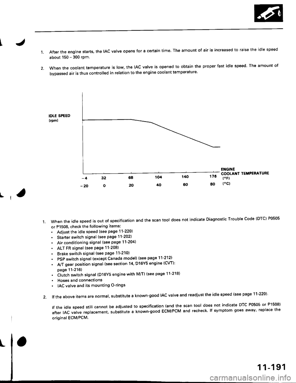
1.After the engine starts, the lAc valve opens for a certain time. The amount of air is increased to raise the idle speed
about 150 - 300 rpm.
When the coolant temperature is tow, the IAC valve is opened to obtain the proper fast idle speed. The amount of
bypassed air is thus controlled in relation to the engine coolant temperature'
IOLE SPEED
lrpml
176
80
ENGI ECOOLANI TEMPERATURE
t" Fl
toc)
ll
't.Whentheid|espeedisoutofspeciiicationandthescantoo|doesnotindicateDiagnosticTroub|ecode(DTc)P0505
or P1508. check the following items:
. Adiust the idle speed {see page 11-220}
. Starter switch signal (see page 11-202)
. Air conditioning signal (see page l1-204)
. ALT FR signal (see Page 11-2081
' Brake switch signal (see page 11-210)
. PSP switch signal (excapt Canada model) (see page 11-212)
. A,/T gear position signal {see section 14, Dl6Y5 engine (CVT):
page 11-216). Clutch switch signal (D16Y5 engine with M/T) (see page 11-218)
. Hoses and connections
' IAC valve and its mounting O-rings
lf the above items are normal, substitute a known-good IAC valve and readjust the idle speed (see page 11-220)
|ftheid|espeedsti||cannotbeadjustedtospecification(andthescantoo|doesnotindicateDTcP0505orP]50S)
after IAC valve replacement. substitute a known-good ECM/PCM and recheck. lf symptom goes away, replace the
original ECM/PCM.
Page 479 of 2189

ldle Control System
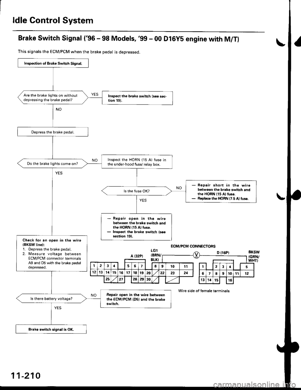
Brake Switch Signal ('96 - 98 Models, '99 - 00 Dl6YS engine with M/Tl
This signals the ECM/PCM when the brake pedal is deoressed.
LGlBKSW(GRN/WHTI
D {16P)
Wire side of female t€rminals
Inspection of Brake Switch Signal.
Are the brake lights on withoutdepressing the brake pedal?
Depress the brake pedal.
Inspect the HORN (15 A) fuse inthe under-hood fuse/ relay box.Do the brake lights come on?
- Repair short in the wirebetween the brake 3whch andrhe HORN 115 At lu3e.- Replace the I|oRN 17.5 A) tus€.
Repair open in the wirebetween the brake switch andthe HORN 115 Al fuse.Inspect th6 br.ke switch {s6€section l9l.Check tor an open in the wireIBKSW line):1. Oepress the brake pedal.2. Measure voltage betweenECM/PCNI connector terminalsAg and D5 with the brake pedaloepresseo.
Repair open in the wire b€tweenthe ECM/PCM {Dsl and the brakeswitch.
ls there battery voltage?
Brakc switch sign.l is OK.
ECM/PCM CONNECTOFS
A (32PtIBRI\v
,la678101112I
121311151617t8192022232aI9101112
25212Aa3013141516
11-210
Page 480 of 2189

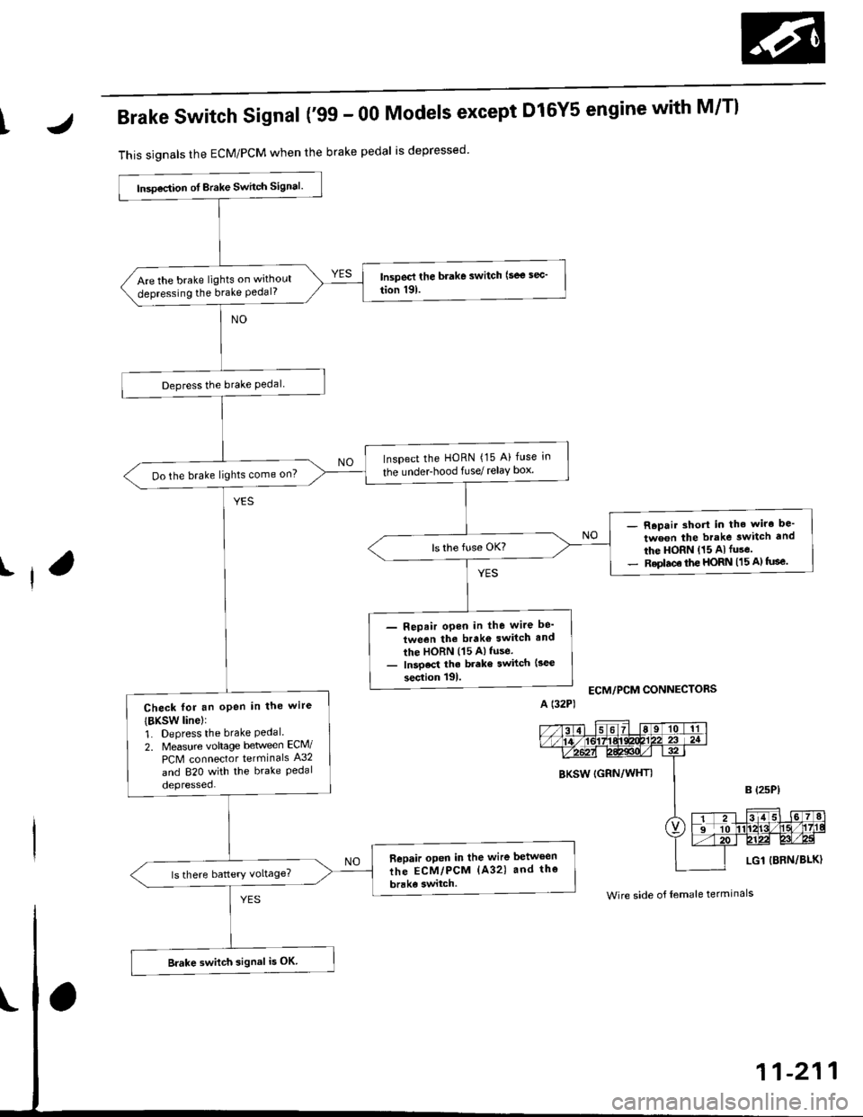
IJBrake Switch Signal ('99 - 00 Models except Dl6Y5 engine with M/Tl
This signals the ECM/PCM when the brake pedal is depressed
I
lnsoection ot Brake Switch signal.
Are the brake lights on without
depressing the brake Pedal?
Depress the brake Pedal
Inspect the HoRN {15 A} fuse in
the underhood fuse/ relay box'Do the brake lights come on?
- R.pair short in the wiro be'
tween the brake switch and
the HORN (15 Alfuse.- Replac€ the HORN (15 A) tuse.
- Repair open in the wite be'
tween the brako switch and
the HORN (15 Alfuse.- lnsoect the brake switch (3ec
section tgl.
Check fot an oPen in the wire
{BKsw linel:
1. Depress the brake Pedal.2. Measure vohage beween ECM/
PCM connector terminals A32
and 820 with the brake Pedaldepressed.
Bepair open in the wire between
the ECM/PCM (A32) and the
brake switch.
Brake switch signal i5 OK
ECM/PCM CONNECTORS
BKSW (GRN/WHTI
LG1 {BRN/BLK)
Wire side o{ female terminals
Page 489 of 2189

ldle Control System
ldle Speed Setting
Inspection/Adiustmenl
'96, '97 Dl6Y5. '96 - 00 Dl5Y8 sngine with M/T
NOTE:
. Before setting the idle speed, check the following
items:- The MIL has not been reported on.- lgnition timing- Spark plugs- Air cleaner- PCV system
o (Canada) Pull the parking brake lever up. Start the
engine, then check that the headlights are off.
1. Start the engine. Hold the engine at 3.000 rpm withno load (taansmission in neutral) until the radiatorfan comes on, then let it idle.
2. Connect a tachometer.
3. Disconnect the IAC valve connector.
4.lf the engine stalls, restart the engine with the accel-
erator pedal slightly depressed. Stabilize the rpm at1,000, then slowly release the pedal until the engineidles.
Check idling in no-load conditionsr headlights. blowerfan. rear defogger, radiator fan, and air conditioner
are not operating.
ldle spsed should be:
450 1 50 rpm
11-220
Adjust the idle speed, if necessary, by removing thecap and turning the idle adjusting screw.
NOTE; After adjusting the idle speed in this step,recheck the ignition timing (see section 23).
lf it is out of spec, go back to step 4.
IDLE
6. Turn the ignition switch OFF.
7. Reconnect the 2P connector on the IAC valve, then
do the ECM reset procedure.
8. Restart and idle the engine with no-load conditionsfor one minute, then check the idle speed.
NOTE: (Canada) Pull the parking brake lever up.Start the engine, then check that the headlights areoff.
ldle sp€sd should b€:
670 i 50 rpm IUSA)750 t 50 rpm {Canada}
9. ldle the engine tor one minute with headlights {Low)ON. and check the idle speed.
ldle speed should be:
750 :r 50 rpm
10. Turn the headlights off. ldle the engine for oneminute with heater fan switch at Hl and air conditioneron, then check the idle speed.
ldle speed should be:
810150 rpm
NOTE: lf the idle speed is not within specification,see Symptom Chan on page 11-84.
Page 554 of 2189

\
\
(From page 11-284)
\(cont'd)
11-285
EVAP PURGE CONTROL SOI.INOID
VALVE 2P CONNECTOR IC114I
Wire side otfemaleterminals
?,
I,l,lil?"",,,u
EL,TWYEL)
Check the EVAP pirrge controlsolenoid valvei1. Disconnect the 2P connector
lrom the EVAP purge control
solenoid valve.
2. Ouickly raise the engine speed
to 3,000 rpm.
ls there vacuum?
InsDect vacuum ho56 routing.ll OK, replace the EVAP Purgecontrol solenoid valve.
Chock for a short in the wire(PCS linel:1. Turn the ignition switch OFF
2. Disconnect ECM/PCM connec'
tor A (32Pi.
3. Check for continuity between
the EVAP PUrge control sole
noid valve 2P connector termi
nal No.2 and body ground.
Check the vacuum when hot:
1. Turn the ignition switch OFF
2. Block the rear wheels and set
the parking brake.3. Jack up the front o{ the vehi-
cle and support it with safety
stands,4. Start the engine. Hold the
engine al 3,000 rpm wlth no
load (in Park or neutral) until
the radiator fan comes on, then
let it idle.5, Check for vacuum at the vac-
uum hose with transmissaonin gear (A/T in B Position,M/T in lst gear) after starting
the engrne.6. Ouickly raise the engine speed
to 3,000 rpm.
Reoair short in the wire botween
the EVAP purg€ cor|t]ol solenoid
valve and the ECM/pcM lA15l.ls there continuity?
Substitute a known-good ECM/
PCM and recheck. lf sYmPtom/indication goes eway. repl.c€ the
original ECM/PCM.
Check the EVAP Purg€ control
solenoid valve:1. Turn the ignition switch OFF
2. Disconnect the 2P connector
from the EVAP Purge control
solenoid valve and warm lt
up to normal operating tem_perature again if necessary
3. Stan the engine.4. At the harness side, measure
voltage between the EVAP
Purge control solenoid valve
2P connector terminal No. 1
and No. 2 with the transmission in gear (A,/T in E Posi-tion, M/T in 1st gear).
In3pect vacuum ho3€ touting.
ll OK, replace EVAP Purge con-
lrol aolenoid vtlv€.
Check lo. an open in the wire
llGl linel:At the harness side, measure volt
age between the EVAP Purge con-
trol solenoid valve 2P connectorterminal No. 1 and body groundRepeir open in tho wire between
EVAP purge conttol solenoid valv€
and the No. 15 ALTERNATOR SP
SENSOR (7.5 A fu3e
IBLK/YELI
lTo page 11 286i(To page 11-286)
Page 559 of 2189

Emission Control System
Ch€ck the EVAP purge controlsolenoid valv6:1. Disconnect the 2P connectorfrom the EVAP purge controlsolenoid valve.2. Ouickly raise the engine speedto 3,000 rpm.
Insped vacuum hose routing.lf OK. roplace the EVAP purge
control solonoid valve.
Chock tor r short in the wir€
{PCS line):1. Turn the ignition switch OFF.2. Disconnect ECM/PCM connec-tor A (32P).
3- Check tor continuity betweenthe EVAP purge control sole-noid valve 2P connector termi-nal No. 2 and body ground.
Check the vacuum when hot:1. Turn the ignition switch OFF.2. Block the rear wheels and setthe parking brake.3. Jack up the lront of the vehi-cle and support it with safetystands.4. Start the engine. Hold theengine at 3,000 rpm with noload (in Park or neutrali until
the radiator fan comes on, thenlet it idle.5. Check for vacuum at the vac-uum hose with transmissionin gear (A/T in E position,
lvl/T in 1st gear) after startingthe engine.6. Ouickly raise the engine speedto 3,000 rpm.
Rooair shoft in the wire belwegnthe EVAP pulg6 control solenoidvalvs and tho ECM/PCM {A61.ls there continuity?
Substitute a known-good ECM/PCM and rech6ck. lt 3ymptom/indicrtion 90e3 rway, r6plac6 th€o.iginal ECM/FCM.
Check th€ EVAP purge controlsolenoid valve:1. Turn the;gnition switch OFF.2. Disconnect the 2P connectorfrom the EVAP purge controlsolenoid valve and warm itup to normal operating tem-perature again if necessary.3. Start the engine.4- At the harness side, measurevoltage between the EVAPpurge control solenoid valve2P connector terminal No. 1and No.2 with the transmis-sion in gear {A/T in E posi-tion, M/T in lst geari.
In3pect vacuum hoae routing.lf OK, repl.ce EVAP purge con-trol solonoid valve.ls there battery voltage?
Chock for an open in the wire(lG1 lina):At the harnoss side, measure volt-age beNveen the EVAP purge con-trol solenoid valve 2P connectorterminal No. 1 and body ground.
Repair open in the wire b€lwe€nEVAP purge contrl 3olenoid valv6and lhe No. 15 ALTERNATOR SPSENSOR 17.5 A, fu3e.
ls there battery voltage?
Evaporative Emission (EVAPI Controls (cont'dl
(From page 11-289)
(To page 11-291)
11-290
IJ
EVAP PURGE CONTROL SOLENOIDVALVE 2P CONNECTOR IC114I
PCS
IRED/YEL)
temaletermrnars
of
PCS(RED/YEL)
tGlIBLK/YEL)
{To page 11 291)