Page 857 of 2189

17.
18.
19.
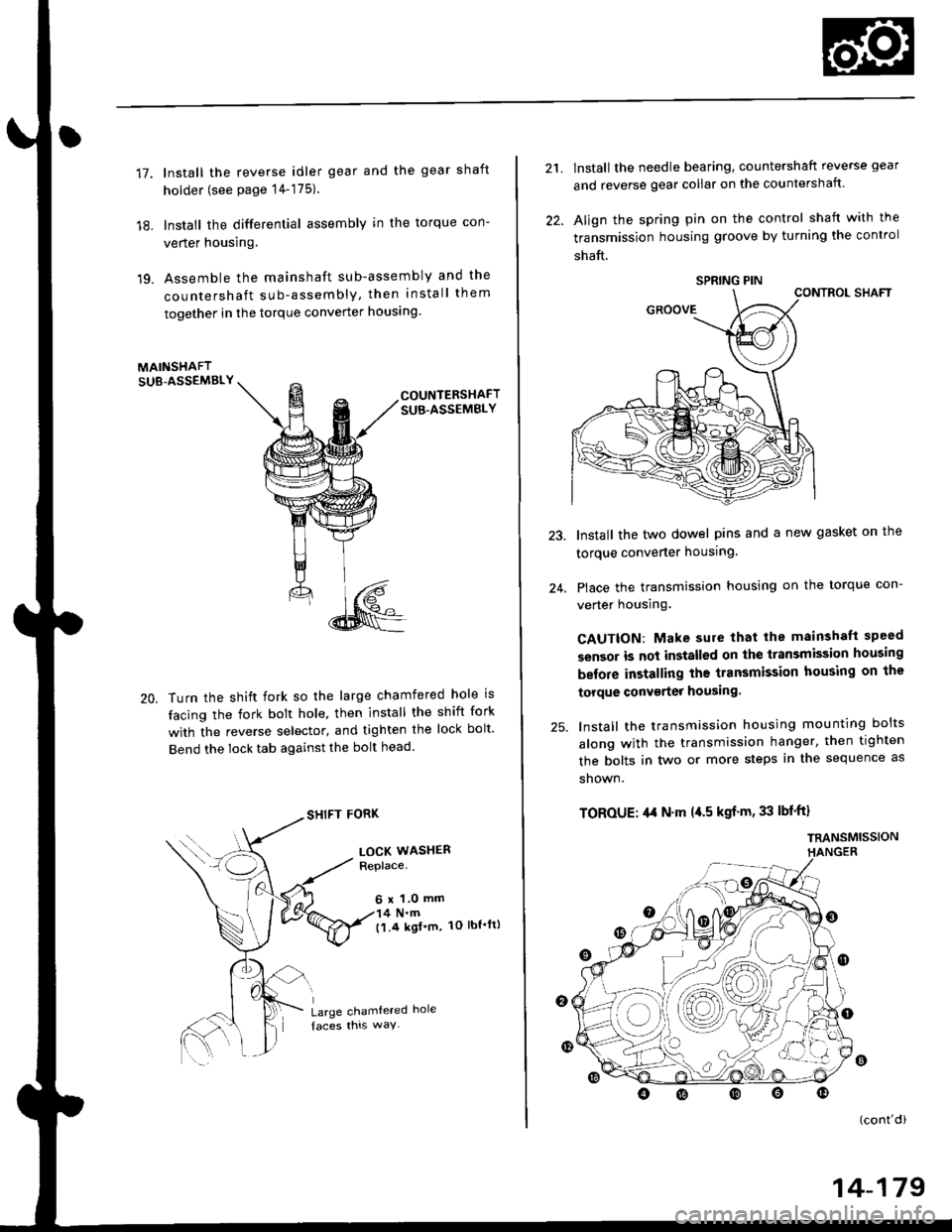
lnstall the reverse idler gear and the gear shaft
holder (see page 14-175).
lnstall the differential assembly in the torque con-
verter housing.
Assemble the mainshaft sub-assembly and the
countershaft sub-assembly, then install them
together in the torque converter houslng
MAINSHAFTSUB-ASSEMBLY
20,
COUNTERSHAFTSUB.ASSEMBLY
Turn the shift fork so the large chamfered hole is
tacing the fork bolt hole, then install the shift fork
with the reverse selector, and tighten the lock bolt'
Bend the lock tab against the bolt head
SHIFT FORK
LOCK WASHERReplace.
6 x 1.0 mm4 N.m('l.4 kgl'm, 1O lbt'ft)
Large chamtered hole
21.
22.
lnstall the needle bearing, countershaft reverse gear
and reverse gear collar on the countershaft.
Align the spring pin on the control shaft with the
transmission housing groove by turning the control
shaft.
CONTROL SHAFT
Install the two dowel pins and a new gasket on the
torque converter housing.
Place the transmission housing on the torque con-
verter housing.
CAUTION: Make sure that lhe mainshaft speed
sensor is not installed on the transmission housing
before installing the transmission housing on the
torque conv€rter housing.
lnstall the transmission housing mounting bolts
along with the transmission hanger, then tighten
the bolts in two or more steps in the sequence as
shown.
TOROUE: ,l,t N'm l{.5 kgf'm, 33 lbf'ft}
TRANSMISSIONHANGER
24.
o
(cont'di
SPRING PIN
14-179
Page 1881 of 2189
NOT-E: Fu^se.31 is HO-f-with lgnition Switch in START (tD and clutch pedat depressed orA"iT Gear Selector in PARK (P) or NEUTRAL (N), see Siarting Systeni, page 2i or 21-2.
See Int€oratedControl Jnit.page 70.
UNDER-OASHFUSE/RELAYBOXPHOTO 58
c420
vtEw 53
PGM-FIMAINRELAY
vtEW 18
|- flrn*',
""-"'l
""^"*l *L
I
016Y5/D16Y8 D16,
;-ensnewrh",r-t :--*f 3l3yi:131ffi,-'' ---
I H;[h- N
i ii jt
lilT:{xsl I
ffifi:iil:"'"" il
-UTtl
i ryffi$il: i i ffifrffi ,,1 _,_:_____r,"*,
,A124 , , A14A, A13A ' 416A C6APOWERTRAIN, , ,^lAcy) (iAcvP) (rAcv N) | crnt $rs): I rAurr'arve , i r--.-, : Fuel pump control Start input ! :rNGtNFi , nt;*Y:l"" , i r--r I Fuel pump conkol Stan input | ;'NG|NElr 'uv"nv' : , IAC valve controt ' ICONTROL\I , I MODULE
t'----- ':------------i l(PcMorEcM)
I t'�;[?,i?"*L------ ---J
(cont'd)
---l-lf -----=-------------=--:
i
"au*", IzI
23-1
Page 1896 of 2189
NOTE: Fuse 3l is HOT with lgnition Switch in START (lll) and clutch pedal depressed or
A'/T Gear Selector in PARK (P) or NEUTRAL (N), see Starting System, page 21 or 21-2.
FUSE 31SIAilEfi SIGT{AL7.fi
UNDER.DASHFUSE/RELAYBOXPHOTO 58See ldeoratodControl Unit,page 70.
1110c420
vtEv,/ 53
PGM-FIMAINRELAY
vlEW 18
-:f]'" l;;;,b"YEUG8N
I
vtEw 40
i fli,i{ry;g:l lr R;::i8i3ll:13rffi:-''
'r
I H[f#'-
il |r'ru*
ljT-.i|ff
| - Friofo 1id | | I | Plioio {- n, 1 Y LJirJ-J plroio 4s tot6v7, I I G552'lt:i:PHotosa
I [ :: ! 'l r------' er-xl iiar-xfi onrl
i*"1 l:"'l I :
: I i: I I :
iazsA ii eoA ers|' , ltol lcql.I POWERTRAIN,a1F--X-lo"i"r t, "u*t : (FLF)
! , lAcvatve I i rq;.,.-...,; : Fu€r pump controt s"liii'p", ! EHc,le:;w, ruEr PqrrPlJtrIulI , connot :; IAC vatve controt , ! CONTROL
(cont'd)
24-1
Page 1907 of 2189
Programmed Fuel Injection System (PGM-F|) (D1685)
NOTE: Fuse 31 is HOT with lgnition Switch in START (lll) and A'/T Gear Selector in PARK (P) or NEUTRAL (N),
see Starting System, page 21-1 .
@
ii6iir-
- -TFU'E;--- - -
I gI3'5"
y#*i[HtF{,iiH.frIHHi Jiffi" !['.iF{,$SNALr5a Y 7.54| - See Inleqrat€dSse Pow€r | --+ ffii;l'i; -- | Phoro 58i ffi ffi:- |EHF? i I
p--',b"
I iffij*,**.,* iFE^l
SACI( UP7,ta
'[-------------'[&T:1,
L.[E"Jj!i_.f;ff:]_j
*L:*
ilTrr,*ii "",""[*=
{ {-
--
;[n*n-
--ftr-'lf
tlGFNYEI
T HI I
rv
J &l?3.,"","'o-,rr ! ,o"on
! #""?,* I
'rT#
*"ll
'fi-----n
h,T5$B.I
J J lvA!::, !
[--iI I
!tl
I onr I can ver- | er-u onn
Itt
A arsl rrsl a24
;t--7;,i----&;-----{IAC valve mnt.ol
;YN
IT/U
ll
v
ToBonlaclngpage
4
FED
I T------i:il;
,oln,.r I """-f-T:
-l-Lri | |d
l
wtl
Iil
i-,"ffifi
- - - - - - -- - -;s,nl - -ffi'J -.'"-
I Oac* rjp input input A
I
I
I|.-------
{F;H:{"
I
I
-"1
,,..!.'-^-*'! PowER-
f,mihHin.
I (PCM)
lif''?;"
25
BIU
Page 1965 of 2189
Integrated Control Unit
NOTE: Fuse 31 is hot with lgnition Switch in START (lll) and clutch pedal depressed or A,/T Gear Selector in
PARK (P) or NEUTRAL (N), see Starting System, page 21,21-1, ot 21-2.
See BrakeSystemlndicatorli^hl
FUSE 3IstaaTEaSIGI{AT7AAI
I
I
I
I
I
\
\
\
\
\
\
I
I
I
I
I
I
/
S€s SiarlingSyslsm, pago 21,21-1. or 21'2.
SEs BrakeSystemlndicetorLight A6
SsaClharSrrESystom
Eog GoundDistlbution,page l,l-7.
L------3c420PHO|O 63vtEw 53
--r-r..r'
FED/BLU
SeeCeilingLightSee Seat Beltand lgnitionKey Remind€rs
t@
i'l-;;,-lH8B'r*| rrmn1gn I FUSEI
i f t*" ig8f"LJr____J PHOTO 7
u'lf tf,%,
S vtEw 3a
wHr/FED
| 3fl3,n'"n
wHr,FED I sYsteh
<--=- !t
,r"r,".0 | ,n"r,".u I
| .l B*?r:"" ,.!,.*,
Page 1967 of 2189

Brake System Indicator Light
- '96-'98 Models
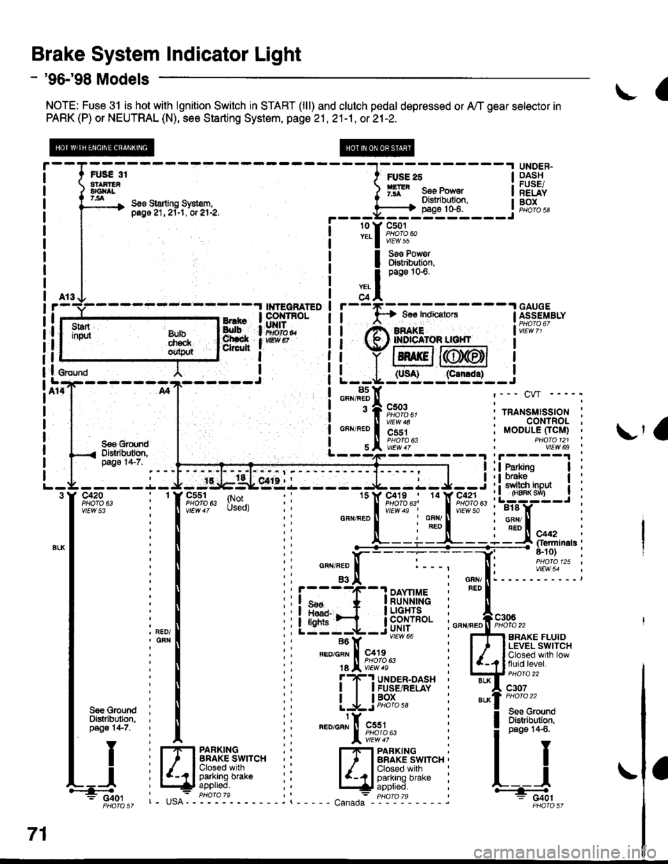
NOTE: Fuse 31 is hot with lgnition Switch in START (lll) and clutch pedal depressed or A,/T gear selector in
PARK (P) or NEUTRAL (N), see Starting System, page 21 , 21-1, or 21-2.
a
FUS€ 31atAirEn8Gl{tt7.all
UNDER-DASHFUSE/RELAYBOXS€o Starling Sysl6m,pag6 21, 2l-1, or el-2,
FUSE 25
ffR s." Ponr"tDistribulion,page 10-6.
rry
I
;?l
r
I
I
I
I
I
I
I
c501PHOTO 60vtEw 55
Ss€ Pow6rDlstribution,page 1G6.
---.I GAUGE$os IndicatorsI ASSEMBLY
i',i!i,I2'
I
I
(slt--95.:l-_i
l8s: GRN/FEDr--- CW ----.
! 3 A cso3 :..^.,"..,"",^.;i "lir%?u' ' rRANsMls-sloN :! ll virw ro : CONTROL ;
99€ grqn'd | ! s I iiiiir^ , vtLw 6s
i o"^r"'o |
'i'jri
| "lw;t,b---4---- 31i3*:'. --l:ffiffi--i
i
---- -.L- J- -:g,tgLesr.l - ---- J--:- J--i : ! 3113'"0* | :-9tF":--T-tY-E;"41i'",
: : lsrss9l;-;?--q1Al" :L:W-J i
-----.1- J- -tlb$Lsr'{.i------ J--:- J--i : ! 31ffi "o* | i-trfr; - -
i
-TFr,lifu:i-|l - - .Tf"*;',r;,f'.F?f;l', i LTS-: :
i I ii
-""'"L--i:t--i3trFlr*n'"i
i mooule ficlrt) iI PHO|O 121 '
:! :i ffitre"ninas;: ll ti n"",".0 ll :---. [: i,119i9."' ''tl
: I :i asi: '.I i eri: -----':::---:
i",",1 iiiffi_il$.t'ii: i"-,s*
vlEw 54
-- vtEot 66 , Ffl anlxe rLUto
i*l
' ".","1;l,"p;a;
illJff*ttt**
u.-u.*il ii [JFHi:"'l*iTfit*,".
I Y i frpanxrxc :' r#"Al[';u3*'""i
I I
U il4.lFfffff'UJ:"" ii EJi,fii,i,"-" i r-j
3"ilj*il
ii
"."""J[ft*,,tl-
i lilt:','x;l
71
i Cior I tE^- phoroTs ,l - : pHoro 7s * C+6tF6r6sz r- usA. - - - - - . t - - - - - canada Froiit sz
Page 1968 of 2189

- '99-'00 Models
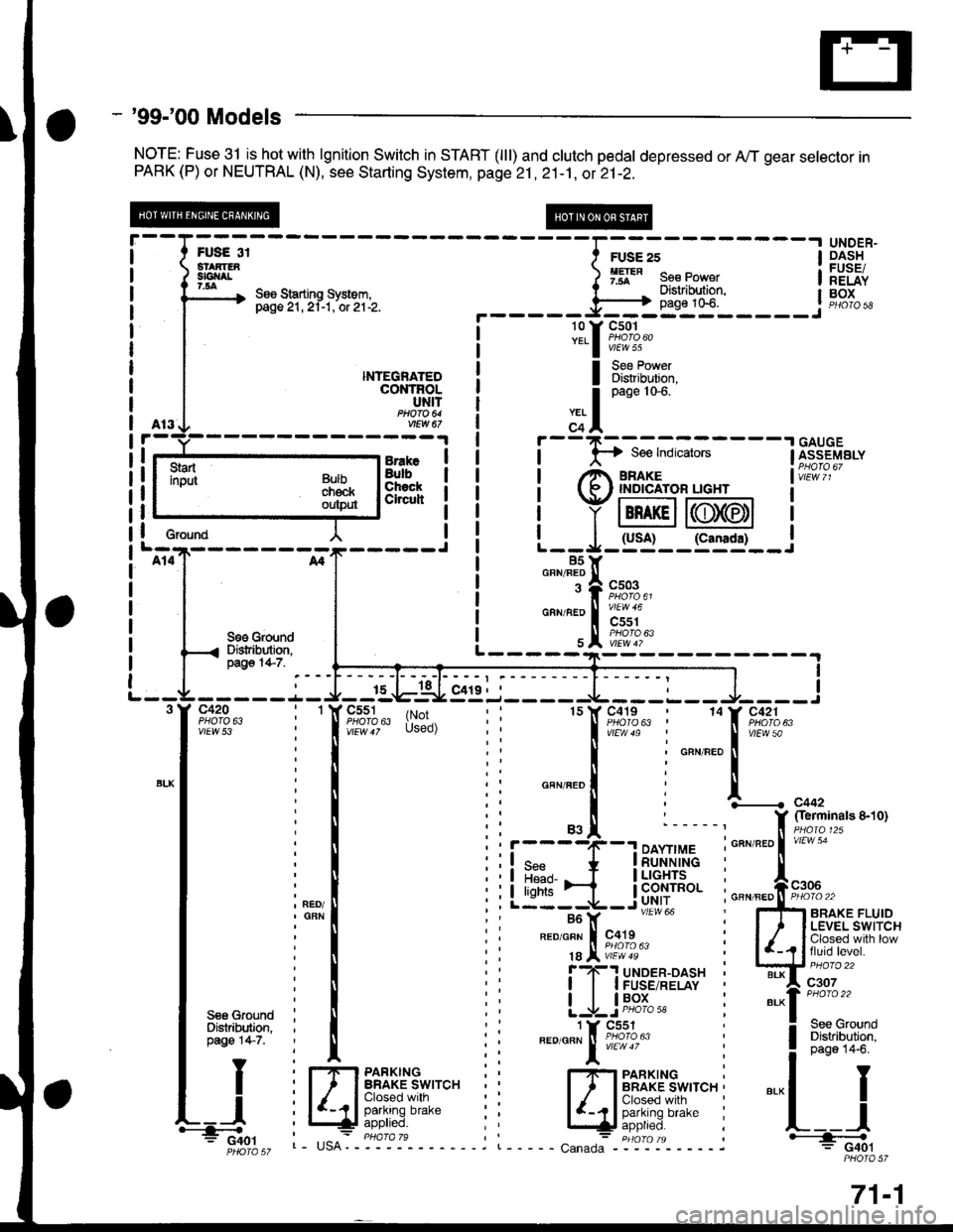
NOTE: Fuse 31 isJtot with lgnition Switch in START (lll) and clutch pedal depressed or A,,/T gear selector inPARK (P) or NEUTRAL (N), see Starting System, page 21 ,2i-1, ot 21-2.
UNDER"DASHFUSEiRELAYBOX
I
I
I
I
I erouna
BrakeBulbChsckCheuh
NTEGNATEDcot{TRoLUNITftoa 64vEw a7
I Bi?[lT':i,
S€6 GroundDistribution,pago 14-7.I
I
c420PHO|O 6ivtEw 53
c551PHOfA 63c419PHO|O 63 |(r;'Used)
1514
r----4(--.1 DAYnMEI q* * |RUNN|NG
Llt:i-ib'f#Iu'"'' i---Y -- """* i
FED/GFN I c419 :
18 Jl iE?'8' :f ?-'! uloen-oasx 'I I I FUSE/RELAY
| | lP9l_- :
1 Y Cs51".o'o"" ! iffl1oru"
l:
I Sss GfoundI Distribution.I pag€ 147.
TY
tt
L_l.'-4o.'
Fr,lrs 3i
--Iil;--------l
3m" ) 9ff" s"" po*"r I
\, See Starting system. I "- . Distribution. l- pasezr.zi-t.'or'ztlz. ._____=Fl}_*t0"_____.1
l3.f ftT:4""
Bulbchekoutp$
L----------
,.. I
o"n" tot'
c+l
i
- -
F-; ffi ;-
- - -
I [i;"s"'"."I rt^ amre I vir:i i,
t (R ' rNprcAroR uGHr I
i Y lBn rcll6T6tl I
| | (usA! (canrda) |L--*-:J- -:--'�-- J85Y85Yo""'"T|
"";%u,
"""'"';i"a#;",
\e#1k"
I
f,............ c44,
f $?'#"ot'to'-*'1;;
GBN/FED II PHOIO 22
5fi ennxe rluroI ' I LEVEL SWITCH
| /_,? lfJ",ii"."gl'.-
w::::"
"'-1":::::-.
! 3:"'lll"*l
".-l I
L__l+: G40lPHOIO 57
l-rlrl PARKTNGI ' I BRAKE SWITCH ,
lIdft"f[]r'"r'" i
c"n"o":- "igt-ol'- - - - - j
71-1
Page 1969 of 2189

Brake System Indicator Light (cont'd)
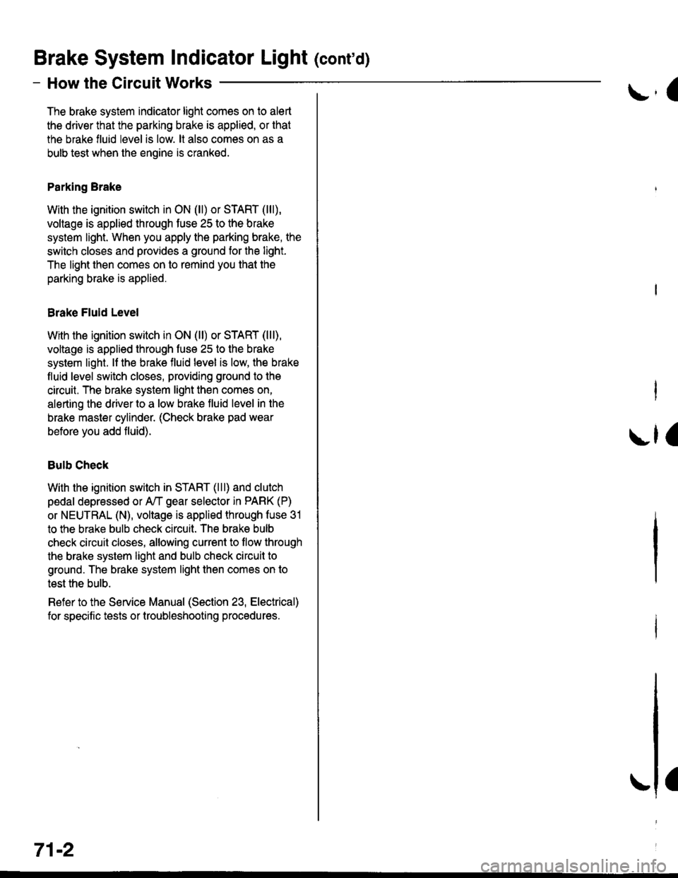
- How the Circuit Works
The brake system indicator light comes on to alert
the driver that the parking brake is applied, or that
the brake fluid level is low. lt also comes on as a
bulb test when the engine is cranked.
Parking Brake
With the ignition switch in ON (ll) or START (lll),
voltage is applied through fuse 25 to the brake
system light. When you apply the parking brake, the
switch closes and provides a ground for the light.
The light then comes on to remind you that the
parking brake is applied.
Brake Fluid Level
With the ignition switch in ON (ll) or START (lll),
voltage is applied through fuse 25 to the brake
system light. lf the brake fluid level is low, the brake
fluid level switch closes, providing ground to the
circuit. The brake system light then comes on,
alerting the d verto a low brake fluid level in the
brake master cylinder. (Check brake pad wear
before you add fluid).
Bulb Check
With the ignition switch in START (lll) and clutch
pedal depressed or A'lT gear selector in PARK (P)
or NEUTRAL (N), voltage is applied through fuse 31
to the brake bulb check circuit. The brake bulb
check circuit closes, allowing current to flow through
the brake system light and bulb check circuit to
ground. The brake system light then comes on to
test the bulb.
Refer to the Service Manual (Section 23, Electrical)
for specific tests or troubleshooting procedures.
71-2
a
\fa