Page 1375 of 2189

Heater
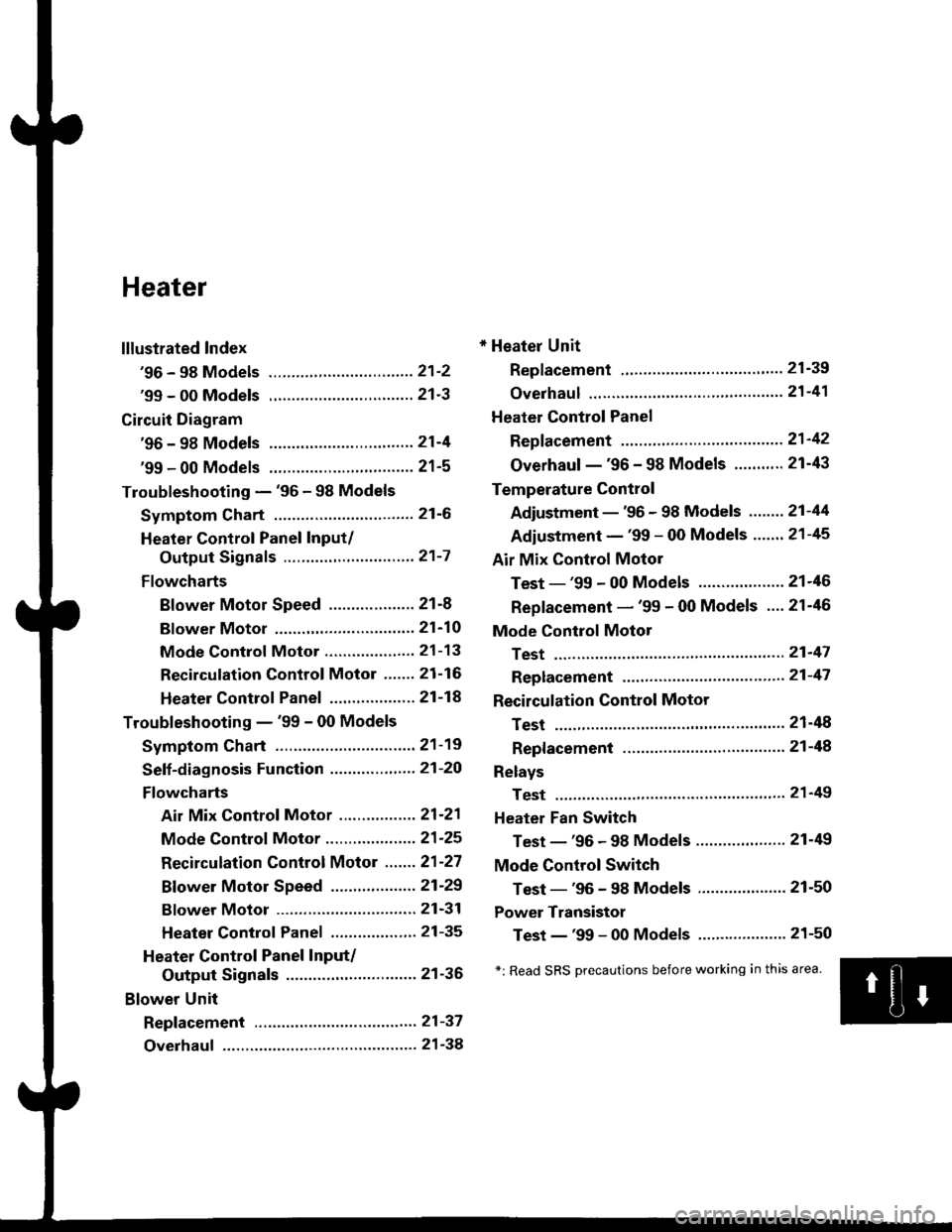
lllustrated Index
'96 - 98 Models ................................ 21'2
'99 - 00 Models ................................ 21'3
Circuit Diagram
'96 - 98 Models .....21-4
'99 - 00 Models ................................ 21-5
Troubleshooting - '96 - 98 Models
Symptom Chart ............................... 21-6
Heater Control Panel Input/
Output Signals ..............,.............. 21-7
Flowcharts
Blower Motor Speed ................... 21-8
Bf ower Motor ,...21'10
Mode Control Motor ............... ,.'.' 21-13
Recirculation control Motor ....... 21-16
Heater Control Panel ................ ... 21 -14
Troubleshooting - '99 - 00 Models
Symptom Chart ............................... 21-19
Seff-diagnosis Function ............,,,.... 21-20
Flowcharts
Air Mix Control Motor ......,.......... 21-21
Mode Control Motor ............... ..... 21 -25
Recirculation Control Motor ....... 21-27
Bf ower Motor Speed .............. .....21'29
Bf ower Motor ....21-31
Heater Control Panel ................,.. 21-35
Heater Control Panel Input/
Output Signals ............................. 21-36
Blower Unit
Repf acement .........21-37
Overhaul ................ 21-38
* Heater Unit
Replacement ....'....21-39
overhaul """" """' 21-4'l
Heater Control Panel
Repfacement .........21'42
Overhaul -'96 - 98 Models ........... 21-43
Temperature Control
Adjustment - '96 - 98 Models """" 21-44
Adiustment - '99 - 00 Models .......21-45
Air Mix Control Motor
Test - '99 - 00 Models ...........' .......21'46
Replacement - '99 - 00 Models ....21'46
Mode Control Motol
Test ................, .,...'.21'47
Replacement '.'."...21-47
Recirculation Control Motor
Test ................. .......21-48
Repf acement ......." 21-48
Relays
Test ................. .......2'l-49
Heater Fan Switch
Test - '96 - 98 Models ............. .......21-49
Mode Control Switch
Test -'96 - 98 Models ..........."....... 21-50
Power Transistor
Test - '99 - 00 Models ....'........ ....".21-50
*: Read SRS Drecautions before working in this area.
Page 1376 of 2189
lllustrated Index
'96 - 98 Models
SRS components are located in this area. Review the SRS component locations, precautions, and procedures in the SRS
section {24) before performing repairs or service.
BLOWER UNITReplacement, page 21-37Overhaul, page 21-38
HEATER UNITBeplacement, page 21-39Overhaul, page 21-41BLOWERRESISTOBTest,
CONTROL MOTORTest, page 21-48Replacement, page 21'48
a/c swtTcH{wirh A/c)
MOO€MOTORTest, page 21 47Replacement, page 21'47
AIR MIX CONTROL CABLEAdjustment, page 2'1-44Replacement, page 21'43
HEATER FANswtTcHTest, page 2l'49
MODEHEATER CONTBOLPANELswrTcHEsTest, page 21 50Rgplacement, page 2'l-42Overhaul, page 21-43
TEMPERATURE CONTROLLEVERAdiustment, page 21 44
Detroster-aqtivated A/C System
Turning the defroster on activates the A,/C and sets the air flow mode to FRESH. lt is possible to turn the A,/C off or to
change the air flow to RECIRCULATE by pressing the A/C bunon or the FRESH/RECIRCULATE button.
21-2
Page 1377 of 2189
'99 - 00 Models
SRS components are located in this area, Review the SRS component locations, precautions, and procedures in the SRS
section (24) betore perfoming repairs or service.
HEATER UNITReplacement, page 21'39
Overhaul, page 21-41
BLOWEB UNITReplacement, page 21-37Overhaul, page 21 38
HEATER FANswtTcH
RECIRCULATIONCONTROL MOTORTest, page 21-48Beplacement, page 21-48
AIR MIX CONTROL MOTOBTest, page 21-46Replacement, page 21 46
BLOWERTest, page 21-49
POWER TRANSISTORTest, page 21 50
HIGH RELAY
MODE CONTROLDIALHEATER VALVE CABLEAdjustment, page 21 45TEMPERATURE CONTROLDIALAdjustment, page 21-45
REAR WINDOWDEFOGGERswtrcHSee section 23MODEMOTORTest, page 21 47Replacement, page 2 l-47A/C SWTTCH
lwith A/cl
CONTROL SWITCH
21-3
Page 1379 of 2189
'99 - 00 Models
UNDER,HOOO FUSE/RELAY 8OX
PUSN SWITCH
lHce nvosrar F)- aLu neo(Wirh IVC)
DASH LIGHTS -/1BBTGNTNESS < l- FEoCONTROLLER -!
IGN TION SW TCHUNDEF DASHFUSElRELAY BOX
**,',,* **",@ ",.
@f
u,n,",,
ELUAVHT
I
YBLUi BtK
BLOWERMOTOR
ELOWERMOTORHIGHRELAY
PNK/BLK
FED''WHT
RED,YEL
GRY
BRN
YEL
YEL/FEO
6RNiYEL
8LU/!VHT
YEL/BLU
BRNfiHT
GFNM/HT
GRNi FED
O :8P CONNECTOR
! :20P CONNECTOF
E : 12P CONNECToR
BLUi BLK
1
tic
HEATER CONTROL PANEL
VENT
MOOEHEAT CONTFOLMOTOF- M.COMDEF
[[f&H,,4*,",,
BLK
Page 1380 of 2189

Troubleshooting -'96 - 98 Models
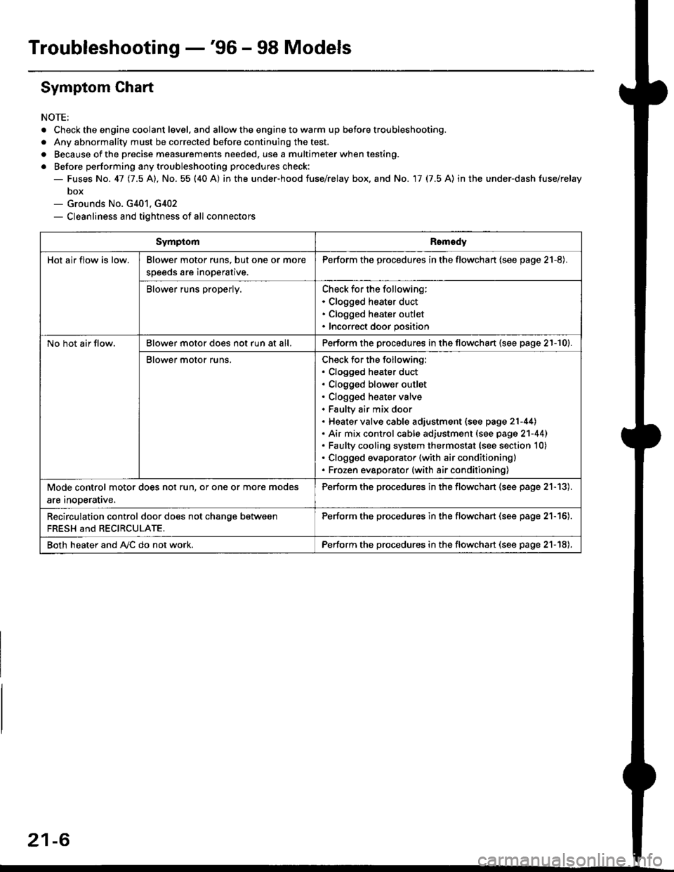
Symptom Chart
NOTE;
. Check the engine coolant level. and allow the engine to warm up before troubleshooting.
. Any abnormality must be corrected before continuing the test.
. Because of the precise measurements needed. use a multimeter when testing.
o Before performing any troubleshooting procedures check:- Fuses No. 41 11.5 Al, No. 55 (40 A) in the under-hood fuse/relay box. and No. 17 (7.5 A) in the under-dash fuse/relay
box- Grounds No. G401, G402- Cleanliness and tightness of all connectors
SymptomRomedy
Hot air flow is low.Blower motor runs. but one or more
speeds are inoperative.
Perform the procedures in the flowchart (see page 21-8).
Blower runs properly.Check for the following:. Clogged heater duct. Clogged heater outlet. Incorrect door position
No hot air flow.Blower motor does not run at all,Perform the procedures in the flowchart (see page 21-10).
Blower motor runs.Check for the following:. Clogged heater duct. Clogged blower outlet. Clogged heater valve. Faultv air mix door. Heater valve cable adjustment (see page 21-44). Air mix control cable adiustment (see page 2'l-441. Faulty cooling system thermostat (see section 10). Clogged evaporator (with air conditioning). Frozen evaporator {with air conditioning)
Mode control motor does not run, or one or more modes
are inooerative.
Perform the procedures in the flowchart (see page 21-13).
Recirculation control door does not chanqe between
FRESH and RECIRCULATE.
Perform the procedu.es in the flowchan (see page 21-16).
Both heater and A,/C do not work.Perform the procedures in the flowchart (see page 21-18),
21-6
Page 1382 of 2189
Troubleshooting -'96 - 98 Models
Blower Motor Speed
HEATER FAN SWITCH 6P CONNECTOR
Wire side of female terminals
21-a
Blower motor runs. but one orrnore speeds are inoperative,
Chsck for a short or an open inthe wire{s}:Turn the ignition switch ON {ll),and the heater fan switch OFF.
Does the blower motor run?
Check for a shon in th6 wirels):1. Turn the ignition switch OFF.2. Disconnect the blower motor2P connector,3. Remove the center dashboardlower cover (see section 20),and disconnect the heater lanswitch 6P connector,4. Disconnect the blower resistor 4P connector,5. Check for continuity betweenthe No. 2,3, 4 and 5lerminalsof the heater fan switch 6Pconnector and body ground
individually.
ls there continuity?Reolace the heater fan switch,
Repair short in the wire(s)beiween the blower resistor, theheater tan switch and the blowermotor,
To page 21 9
Page 1383 of 2189
ls there approx. 2 - 3 ohms?
Check for an open in the wire(s):1. Reconnect the blower resistor
4P connector,2. Remove the center dashboardlower cover (see section 20),and disconnect the heater fanswitch 6P connector.3. Turn the ignition switch ON (ll).
4. Ground each of these termi-nals individually in the tollow_ing order: No. 4, 2, 5 and 3.
Does the blower motor run atprogressively higher speeds?Reolace the hoater fan switch.
Repair open or cause ol excessiveresistance in the appropriatewire{sl between the blower resis-tor and the heater {an switch.
Check the blower resislor:1. Turn the ignitjon switch OFF.2. Disconnect the blower resistor 4P connector.3, N4easure the resistancebetween the No. 2 and No. 4
terminals of the blower resis-tor,
BLOWER RESISTOR
HEATER FAN SWITCH 6P CONNECTOR
BLU/WHT
2
16
BLUBLU/YEL
BLU/BLK
JUMPERWIRE
Wire side of female terminals
21-9
Page 1384 of 2189
Troubleshooting -'96 - 98 Models
Blower Motor
BLOWER MOTOR 2P CONNECTOR
Wi.e side of fernale terminals
f=
l1l
r,l
ruumifalulau**'
I
Fl gr-urwnr
l1|_-_-l
t4 ,t
I
glower motor does not run at all.
Check the No.55 (40A)luse in theunder hood fuse/relay box, andthe No. 17 (7.5 A) luse in theundeFdash luse/relay box.
Repl.ce th. fuse{rl, .nd rochack.
Check the blower motor:1. Connect the No. 2 terminal ofthe blower motor 2P connoctor to body ground with a
lumper wrre.2. Turn the ignition switch ON (ll).
Does the blower motor run?
Chock for an opsn in the wire:1. Disconnect the ,umper wireand the blower motor 2P con-nector,2. Measure the voltage betweenthe No. 1 terminal and bodyground.
ls there battery voltage?
Ch6ck tha blower motor relay:1. Turn the ignition switch OFF.2. Remove the blower motorrelay from the under-hoodfuse/relay box, and test it (see
page 21-49).
Replace tha blower moior reley.
To page 21-11
fo page21'12
21-10