Page 1537 of 2189
Power Distribution
tCircuit ldentification
CONTROL
V
IGRNMHT
UNDER-HOODABSFUSEi RELAY BOX
'96-98 models: 99-00 models
WHT'GBN - l ABs conlrorun
ABS Aimp molor
*2
BRN,ryEL
YEUREDI ABS conltolun t
Slaner molor
WHT/BLK ..........-
WHT/GRN _-
WHTiGBN
GRN/RED -
Hazard waming liglTun signal/hazard re ay{Via swlch)
HOTN
HOn re ay
ABs controllnilECMi PCMTCM (CW)rlCruise conlrol unilErake lrghls
EC}?VPCM
I-"-
G401G402
I... UNOER.DASHw_T BLU -13 > F-SE ?ELAY BCxt- Fa Nge23:t)
Audio unilTCM (CW)',ECM/PCMHealer conlrolpanel
(cont'd)
23-67
UNDER HOODFUSEi RELAY BOX
ALTERNATOR
VNo 15 (7 sA) FUSE Y(From page 23 70) |
f7 r_1
I_ .,.-.,
*,,,,,* _$ lg|[|];gil.' ('^')
WHT/8LK -
Ceiling lighlTrunkllghrSpollighl *'�
Dala link connecor (DLc)Integraled control unil
PGM Fl main relay
Page 1582 of 2189
Charging System
Component Location Index
UNDER.HOOD FUSE/RELAY BOX/*Has replaceable ELECTRICAL LOAD II DETECTOR (ELD) UNIT '
Troubleshooting, page 23-1 14Replacement, page 23-120Bectifier Removal, page 23,121Rectifier Test, page 23-122Rear Bearing Replacement, page 23-j24
*ELD unit: USA
CHARGING SYSTEM LIGHT(ln the gauge assembly)Test, page 23- l14
BATTERYTest, page 23-91
ALTERNATOR BELTInspection and Adjustment, page 23-t25
[]
23-112
Page 1584 of 2189

Charging System
Troubleshooting
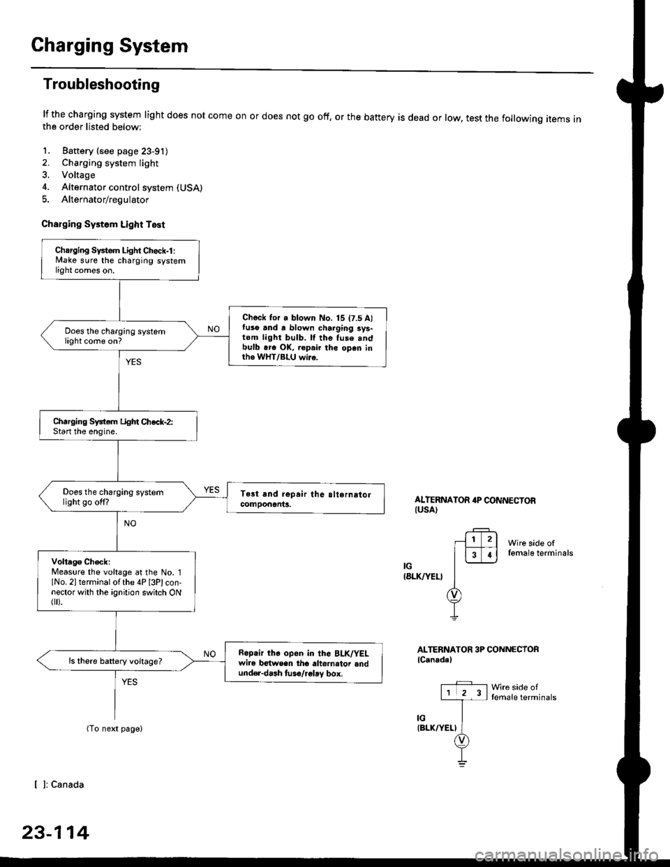
lf the charging system light does not come onthe order listed below:
1. Baftery (see page 23-91)
2. Charging system light
3. Voltage
4. Alternator control system (USA)
5. Alternator/regulator
Charging Systom Light Test
or does not go off, or the battery is dead or low, test the following items in
ALTERNATOR 4P CONNECTORIUSA)
Wire side offemale terminals
IG(8LK/YEL}
ALTERNATOR 3P CONNECTORlC.nadal
Wre side oftemale terminals
[ ]: Canada
23-114
Charging Svstem Light Check-l :lvlake sure the charging systemlight comes on.
Check for a blown No. 15 t7.5 A)fuso .nd a blown charging sys-tom light bulb. ll the fuse .ndbulb .re OK, ropair the open inth6 WHT/BLU wi16.
Does the charging systemlight come on?
Charging System Light Chec*-2:Start the enoine.
Does the charging systemlight go off?
Volta96 ChecklMeaslre the voltage at the No. 1lNo. 2l terminal of the 4P [3Plcon-nector with the ignition switch ONflr).
R6p.ir the op6n in the BLK/YELwire b€twsen tho altornator andund€r-dash tuso/.glay box.
ls there battery voltage?
Page 1601 of 2189
IJNOER,DASHFUSE/RELAY BOX
GAUGELIGHTS
l3wx4 l
CHARGINGSYSTEMLIGHT0.4w)
Gircuit Diagram
UNDEN HOOD FUSE/RELAY BOXIJ
N0.30 (7.54)FUSE
f7
I
tlRED/BLK BEO/BLK
l"l"8LK BLU
IJ
l'"^*
I
t-
G401G402
__l
tE2
IFED/BLU
CRUISECONTROTUNIT
fl ,,1:
tH
I c12
IFFD
VDASH LIGHTSBRIGHTNESSCONTROLLEF
l"'WHT/BLU
vALTERNATOR
(With shifi-up indicatd lighl)(wi1h cruise conlrcl system)
Page 1829 of 2189

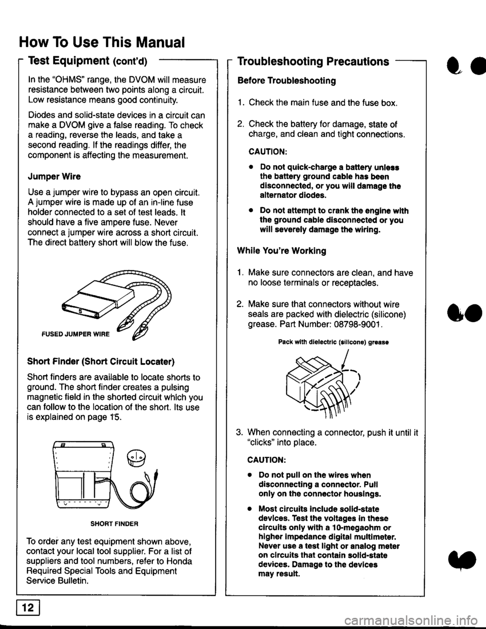
In the "OHMS" range, the DVOM will measure
resistance between two points along a circuit.
Low resistance means good continuity.
Diodes and solid-state devices in a circuit can
make a DVOM give a false reading. To check
a reading, reverse the leads, and take a
second reading. lf the readings differ, the
component is affecting lhe measurement.
Jumper Wire
Use a jumper wire to bypass an open circuit.
A iumper wire is made up ot an in-line fuse
holder connected to a set of test leads. lt
should have a five amoere fuse. Never
connect a jumper wire across a short circuit.
The direct battery short will blow the fuse.
Short Finder (Short Circuit Locater)
Short finders are available to locale shorts to
ground. The short tinder creates a pulsing
magnetic field in the shorted circuit whlch you
can follow to the location of the short. lts use
is explained on page 15.
SHORT FINDER
To ordei any test equipment shown above,
contact your local tool supplier. For a list of
suppliers and tool numbers, refer to Honda
Required Special Tools and Equipment
Service Bulletin.
How To Use This Manual
Test Equipment (cont'd)
oa
Troubleshooting Precautions
Before Troubleshooting
1. Check the main fuse and the fuse box.
2. Check the battery for damage, state of
charge, and clean and tight connections.
CAUTION:
. Do not quick-charge a battery unlers
the battery ground cable has been
disconnected, or you will damage the
alternator diodes.
. Do not attempt to crank the engine wlth
the ground cable disconnected or you
will severely damage the wiring.
While You're Working
1. Make sure connectors are clean, and have
no loose terminals or receptacles.
2. Make sure lhat connectors without wire
seals are packed with dielectric (silicone)
grease. Part Number: 08798-9001 .
Pack wllh dlelectrlc (sillcons) greass
When connecting a connector, push it until it"clicks" into place.
Do not pull on the wires when
disconnecting a connector. Pull
only on the connector houslngs.
Most circuits Include solid-state
devlces. Test the voltages In these
circuits only with a lo-megaohm or
higher impedance digital multlm6ter.
Never use a test light or analog meter
on chcuits that contain solld-state
devices. Damage to the devices
may result.
oo
Page 1835 of 2189

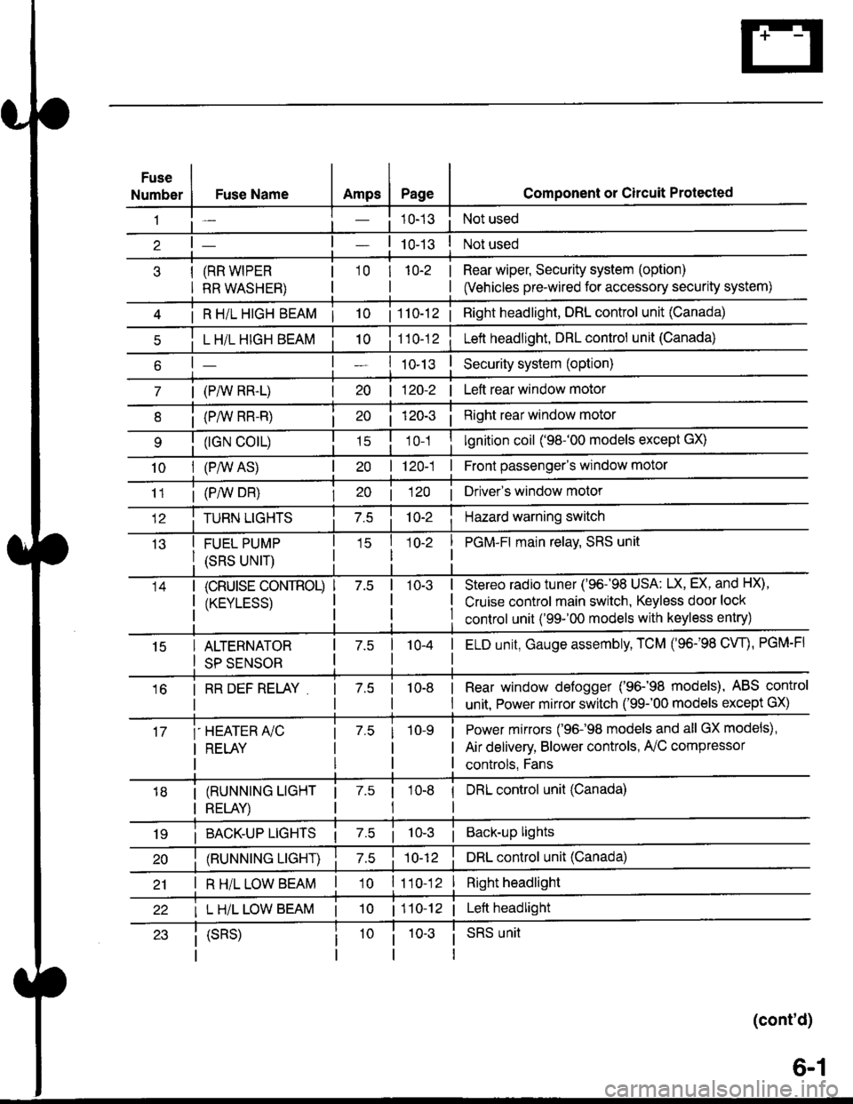
Fuse
NumberAmpsPageFuse Name
(RR WIPER
RR WASHER)
i R HiL HIGH BEAM | 10
L H/L HIGH BEAM
| (PAIV RR-L)
i (P/vv RR-R)
(rGN CO|L)
10I (P,^/V AS)
Component or Circuit Protected
Not used
Not used
Rear wiper, Security system (option)
(Vehicles pre-wired for accessory security system)
'10r 1n-2
I
| 1 10-12i Right headlight, DRL control unit (Canada)
Lett headlight, DRL control unit (Canada)
I ro-rsSecurity system (option)
| 120-2 | Left rear window motor
Right rear window motor
lgnition coil ('98-'00 models except GX)
| 120-1 | Front passenger's window motor
i (PiW DH)| 20 1 12O I Driver's window motor
TURN LIGHTSHazard warning switch
FUEL PUMP
(SRS UNIT)
PGM-FI main relav, SRS unit
(cRUrsE CoNTROL)
/KtrVt trSS\
Stereo radio tuner ('96-'98 USA: LX, EX, and HX),
Cruise control main switch, Keyless door lock
control unit ('99-'00 models with keyless entry)
15ALTERNATOR
SP SENSOR
l-a10-4I ELD unit, Gauge assembly, TCM (96-'98 CW, PGM-FI
16I RR DEF RELAY7.510-8I Rear window defogger ('96-'98 models), ABS control
I unit. Power mirror switch ('99-'00 models except GX)
i-HEATER r/C
I RELAY
Power mirrors ('96-98 models and all GX models),
Air delivery, Blower controls, AilC compressor
controls, Fans
I (RUNNING LIGHT
I RELAY)
1 7.5 1
tl
I DRL control unit (Canada)
i BACK-UP LTGHTSi Back-up lights
(RUNNING LIGHT)DRL control unit (Canada)
I R H/L LOW BEAM'10 l11o-12Right headlight
I L H/L LOW BEAM | 101110-12 | Left headlight
(cont'd)
(SRS)SRS unit
6-1
Page 1878 of 2189
Charging System
See PowerDistribution,pag6 10.
UNDER-HOODFUSE/RELAYBOX
FUSE 15ALT€IIIAIONsP SEII|SOF7.5A
I
t
USA
' BLKAVHTBLKI"VI/HT
-)l,------J
vtEw 50
See PowerDistribution,page 10-5.
* = 96-98rAllmodelsexcept 01685'99 '00: D16Y5 withi.4/T** = '96'�98: All models'99r00: D16Y5 witht\4/T, D1685
BATTERY
ALTERNATOR
See PowerDiskibution,page 10.
FUSE 41BATTEFY804
T101
L-----
ELECTFICALLOADDETECTOR(ELO) UNIT
'l
;l
:l
:l;l
:l
tl,l
:l
:l
G1!
- -I POWER-I -. ^ "'.1 , I rnlrn or
(.A1e)Y '('� C17)c2[ : cs
i ELD unit input i ietCrHe! ' ! coNrRoLI I MODULEI Art€rnator : lllerlato.r I (PCM or
i controrsrsnar i t",fl?il"' a:"^y]L- ----,1- - - - J Pq_oro 3'
*. B,'"',1; :.i
i:1E15_'_
_. i
GFN/FED
r i6
GFN/RED
A30
f D16)WHT/REO*Fi
See Ground IDistribution, Ipage 14-5. I
YT
L]
' ""- PHA|O
,.^;?f, :('c;3)T BLXYEL
I i 'r", ".o II'HT/ ll ' U,zscnrl :-' oi .l
, L : (c'r9ill-_- 'c11" 2)u
l9nitionrnput
LOaO
Ground ourpur
22
Page 2144 of 2189
Connector
or
Terminal
Number of
Cavitiesl
Color
LocationConnects toNotes
Engine Wire Harness (D16Y5, D16Y8 engines): '9&98 models and'9$'fl) D16Y5 dIWT (cont'd)
T101
r102
Lett side of engine
Right side of engine compartment
Alternator
Under-hood fuse/relay box
G101Right of engineEngine ground. via engine wire hamess
'1: D16Y5 engine.2: D16Yg engine'3: D16Y5 (A,/T). D16Y8 enoines'4: '96 model: dtl coupes,'97 model: all coupes, California Sedan,'98-'00 model: all
'96-'98 models and '99-'00 D16Y5 dM/T:
Ic138cl13 Tlorclllcr19 Ic109c110
c141.
T102.
c147-
cl4:t'
cl17'clal
c1|{)
cl18
c139
cl20
c129
c1a6
c1a5
€NGINE wlREHARNESS
cl l5
c116
c137
cr02
c105
c106
)-f
203-3