Page 469 of 2189
ldle Gontrol System
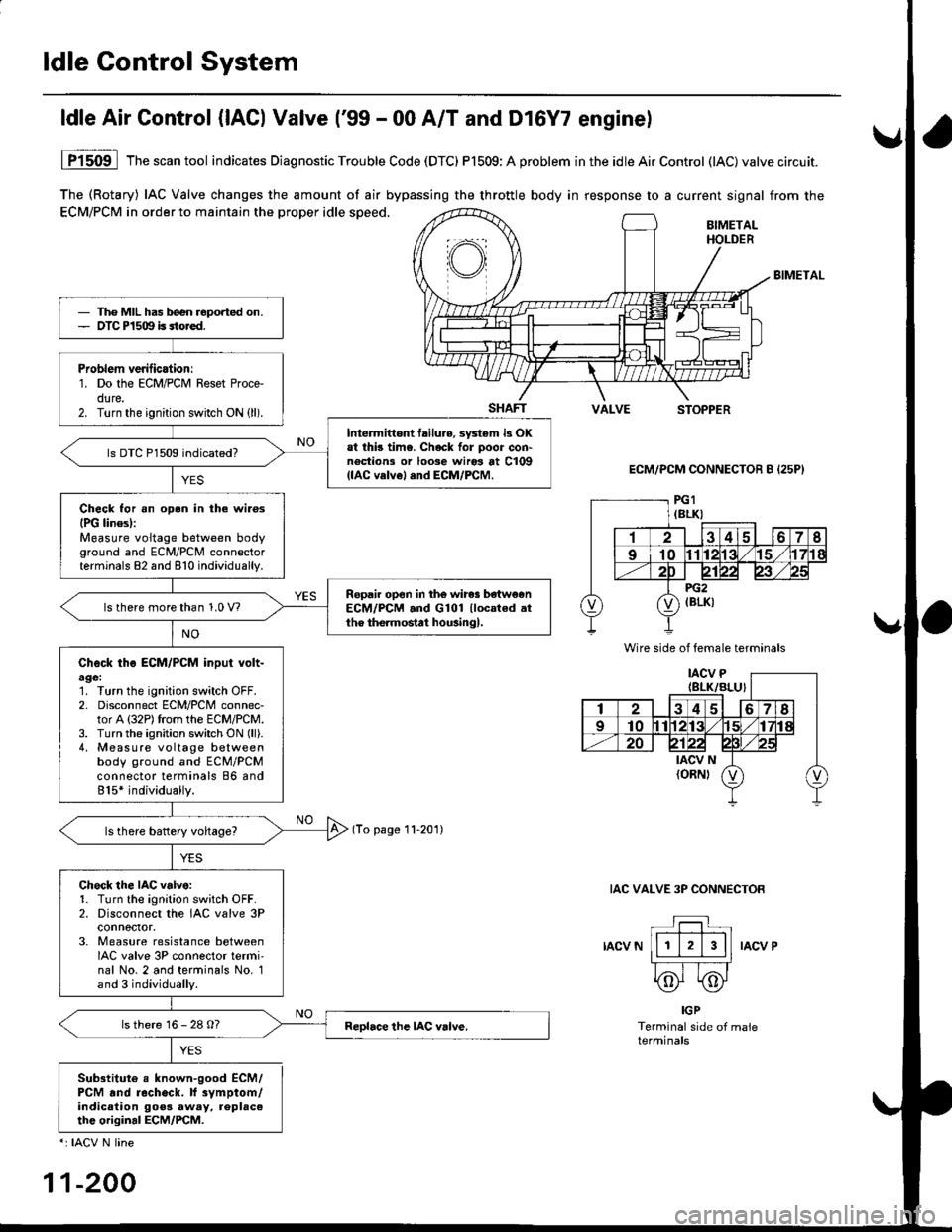
The (Rotary) IAC Valve changes the amount of air bypassing the throttle body in response to a current signal from the
ECM/PCM in order to maintain the proper idle speed.BIMETALHOLDER
BIMETAL
SHAFTVALVESTOPPER
ECM/PCM CONNECTOR B {25P}
(To page 11-201)
IAC VALVE 3P CONNECTOR
IACV NIACV P
ldle Air Control {lACl Valve ('99 - 00 A/T and Dl6Y7 enginel
YES
1P1509 lThescantool indicates Diagnostic Trouble Code (DTC) P1509:A problem inthe idleAirControl (lAC)valve circuit.
IGP
Terminal side of maleterminals
Sub3titute e known-good ECM/PCM .nd recheck. lf 3vmptom/indicalion goos away, replac6thc original ECM/PCM.
*: IACV N line
11-200
Tho MIL has b€en reported on.OTC P1509 is sto.ed.
Problem verilicationr1. Do the ECM/PCM Reset Proce-dure.2. Turn the ignition switch ON (ll).
Intermittont tailure, sy3tem i3 OKat thb time. Check for poor con'noctions or loose wiros at C109(lAC velvel and ECM/PCM.
ls DTC P1509 indicated?
Check for an oDen in the wilosIPG linesl:Measure voltage between bodyground and ECM/PCM connectorterminals 82 and 810 individually.
Ropail open in the wires be'tw€enECM/PCM .nd G101 llocated .tthe the.mostat housingl.ls there more than 1.0 V?
Check tho ECM/PCM input volt-age:1. Turn the ignition switch OFF.2. Disconnect ECM/PCM connec-tor A (32P)trom the ECM/PCM.3. Turn the ignition switch ON (ll).
4, Measure voltage betweenbody ground and ECM/PCMconnector terminals 86 and815* individually.
Chock the IAC v.lve:1. Turn the ignition sw;tch OFF.2. Disconnect the IAC valve 3Pconnoctor.3. Measure resistance betweenIAC valve 3P connector termi'nal No. 2 and terminals No. 1and 3 individually.
ls there 16 - 28 O?
Wire side of female terminals
Page 471 of 2189
ldle Control System
Starter Switch Signal ('96 - 98 Models,'99 - 00 D16Y5 engine with M/Tl
Thjs signals the ECM/PCM when the engine is cranking.
NOTE:. A/T: Transmission in E or E position. M/T: in neutral
a l32PlLGl
Wire side ot female lerminals
Check tor an open or short in thewire ISTS linel:Measure voltage between ECM/PCM connector terminals A9 andC6 with the ignition switch in thestart lllli position.
Inspect the No. 31 STARTER SIG-NAL (7.5 A) fuse in the underdashfuse/relay box.
- Repair .hort in the wirebotwoen tha ECM {C6l andtho No, 31 STARTER SIGNAL{7.5 Al tuss or the PGM-FImain relay,- Roolac. the No. 3'l STARTERSIGNAL l?.5 Al tu3€.
Staner 3witch signal is OK.
Repair opon in th6 wiro botweanih. ECII4/PCM (C6) and the No.31STARTER SIGNAL {7.5 Al tulo.
ECM/PCM CONNECTORS
{BRN/BLKISTS IBLU/ORNI
216910It3567a9l0
l2l3la15!6171a1920222att12t3l4t5t6171E
252l2A7t30232a2930
11-202
Page 473 of 2189
ldle Gontrol System
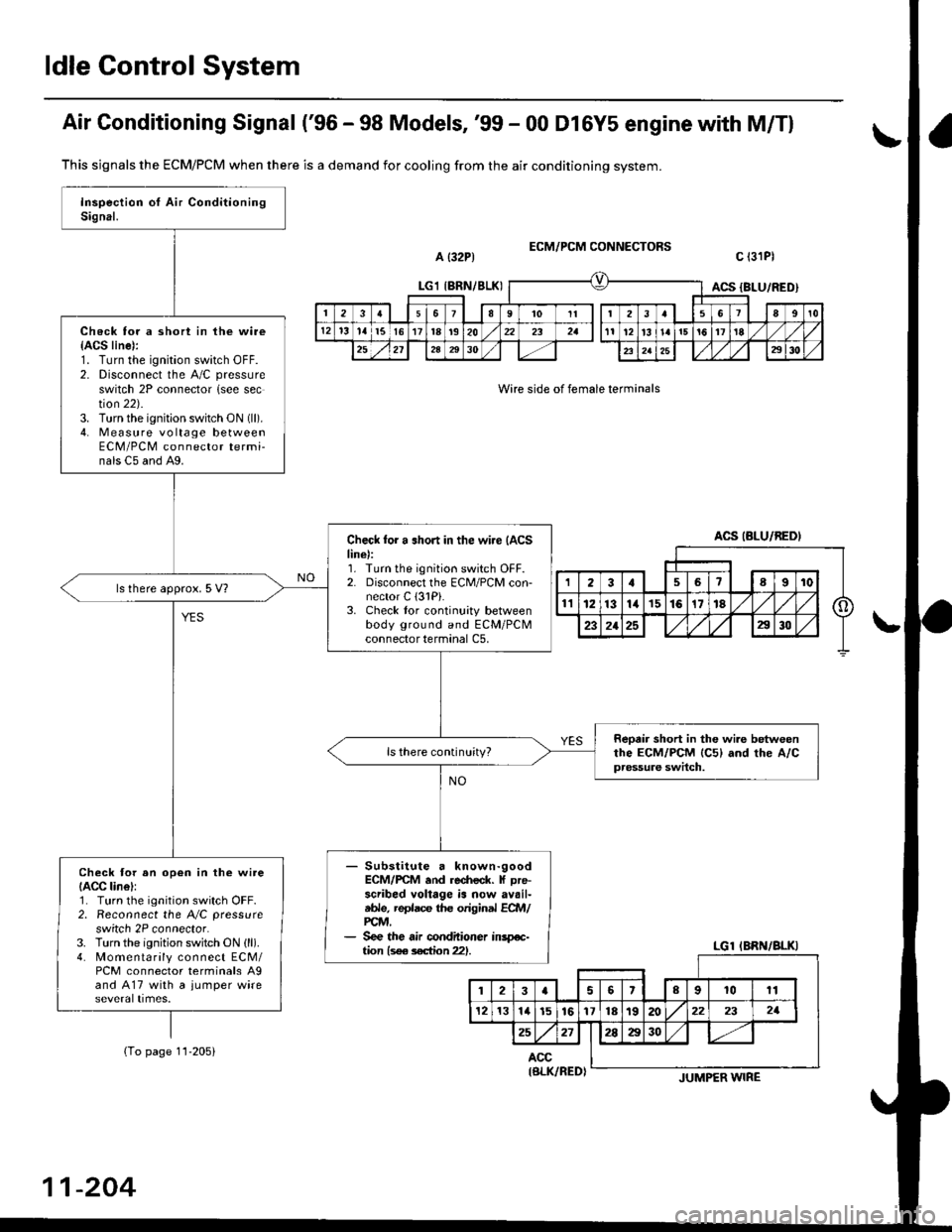
Air Gonditioning Signal ('96 - 98 Models, '99 - 00 Dl6Y5 engine with M/Tl
a {32P1ECM/PCM CONNECTORS
Wire side of female terminals
c l3lPl
This sjgnals the ECM/PCM when there is a demand for cooling from the air conditioning system.
(To page 11-205)
Check for a short in the wire{ACS line):1. Turn the ignition switch OFF.2. Disconnect the A/C pressure
switch 2P connector {see section 22).3. Turn the ignition switch ON (ll).
4. Measure vo lta ge betweenECM/PCM connector termi-nals C5 and A9.
Check for a .hort in the wi.e {ACSline):1. Turn the ignition switch OFF.2. Disconnect the ECM/PCM con-nector C (3lPi.
3. Check tor continuity betweenbody ground and ECM/PCMconnector terminal C5,
ls there approx. 5 V?
Reotir short in the wi.e betweenthe ECM/PCM lc5l and rhe A/Cpressure switch.
ls there continuity?
- Substitute a known-goodECM/rcM .nd re.fieck. f Dre-scribed voltage is now availtble, replace the original ECft4/PCM,- See the air conditioner inspe-tion ls€e s€ction 221.
Check tor an op€n in the wireIACC lin6l:1. Turn the ignition switch OFF.2. Reconnect the A/C pressure
switch 2P connector.3. Turn the ignition switch ON (ll).
4. Momentarily connect ECM/PCM connector terminals A9and A17 with a jumper wire
LGl IBRN/8LKIACS {BLU/RED)
2361I9't0Itt3a89t0
12't31al5l617t8t920232all12l3l!ai5!617'tE
252l2A2930232a252930
ACS (BLU/BEDI
LGl IBRN/BLKI
123aslslrl lolgl ro lrr I
121314l516y)nltslnl/@) zr I zr I
25271!M1 1-/r
ACC
11-204
IBLK/RED)JUMPER WIRE
Page 475 of 2189
ldle Control System
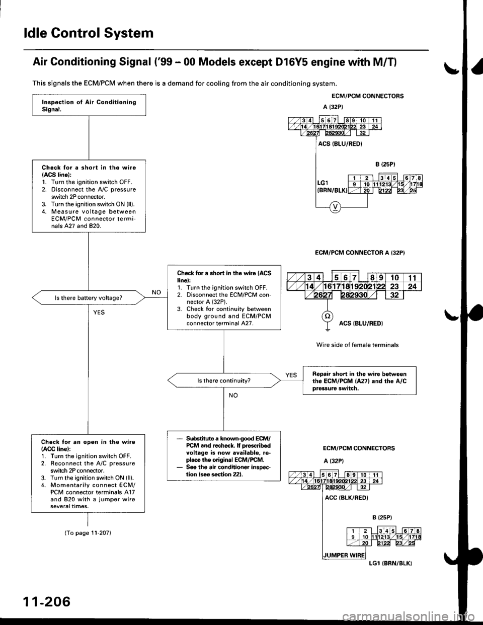
Air Conditioning Signal ('99 - 00 Models except Dl6Y5 engine with M/Tl
This signals the ECM/PCM when there is a demand for cooling from the air conditioning system.
ECM/PCM CONNECTORS
a l32P)
ECM/PCM CONNECTOR A {32P)
Wire side of female terminals
ECM/PCM CONNECTORS
A (32P1
Chock tor a short in ihe wi.e(ACS lin6):1. Turn the ignition switch OFF.2. Disconnect the A/C pressure
switch 2P connector.3. Turn the ignition switch ON (ll).
4. Measure vo ltage betweenECM/PCM connector terminals A27 and 820.
Check for a short in the wire (ACS
linel:'1. Turn the ignition switch OFF.2. Disconnect the ECM/PCM connector A (32P).
3. Check lor continuity betweenbody ground and ECM/PCMconnector terminal A27.
Reoair short in lhe wi.e botweonthe ECM/PCM (A271 and rhe A/Cpressure swilch.
Srr66tituto a known{ood ECM/PCt4 tnd rechock. It prascrib€dvoltage is now available, re-plac€ the original ECM/rcM.Soo the air conditioner insoec-tion {see s€ction 22}.
Check to. an opon in tho wi.e(ACC linel:1. Turn the ignition switch OFF.2. Reconnect the A/C pressure
switch 2P conneclor.3. Turn the ignition switch ON (ll).
4. Momentarily connect ECN4/PCM connector terminals A17and 820 with a jumper wire
(To page '! 1-207)
11-206
LGl {BRN/BLK)
Page 477 of 2189

ldle Control System
Alternator (ALTI FR Signal {'96 - 98 Models,'99 - 00 Dl6y5 engine with M/Tl
ECM/PCM CONNECTORS
a {32P)
LGl(BRN/BLK)
Wire side of female terminals
ALT CONNECTORS IC1O4I
JUMPER
JUMPER WIRE
WIRE
Wire side of female terminals
ALT F{WHT/REO)
This signals the ECM/PCM when the Alternator (ALT) is charging.
Inspoction of ALT FR Signal.
Check tor a short in tfte wire (ALTF linel:1. oisconnect the 4P (3P)* con-nector from the ALT.2. Turn the ignition switch ON (ll).3. M easu re voltage betweenECM/PCM connector terminals C17 and A9.Check lor a sho.t in the wire {ALTF line):r. I urn rne tgn|lton swtlch ul-f,2. Disconnect the negative bat-tery cable from the baftery.3. Disconnect the ECM/PCM connector C {31P).4. Check for continuity betweenbody ground and ECM/PCMconnector terminal C17.
ls there approx. 5 V?
Check th€ operation of the ALT:1. Turn the ignition switch OFF.2. Reconnect the ALT 4P (3P)*connector to the ALT.3. Start the engine. Hold theengine at 3,000 rpm with noload (in Park or neutral) untjlthe radiator fan comes on, thenlet it idle.4. [,4easu re voltage betweenECM/PCM connector terminalsC17 and A9.
Repair short in the wire betwe€nthe ECM/PCM {Cl71and th€ ALT.
Substitute a known-good ECM/PCM and recheck. It prescribedvoltage is now available, roplacethe originrl ECM/PCM.
Does the voltage decrease whenheadlights and rear defogger areturned on?ALT FR signal is OK.
Check tor an open in the wire (AlTF linel:1. Turn the ignition switch OFF.2. Disconnect the negative bat-tery cable from the battery.3. Disco n nect the ECM/PCMconnector C (31P).4. Disconnect the 4P (3P)* con,nector from the ALT.5. Connect the ALT 4P 13P)l connector terminal No. 4 (No. 1)'to body ground with a iumper
6. Check lor continuity betweenbody ground and ECM/PCMconnector terminal C17,
Repair op6n wire botween th€ECM/PCM (C171rnd th€ ALT.ls there continuity?
c {31P)
1178I10
1112131415161718
232125a30
oALT F IWHT/REDI
4P3P*
1 2l
Flr
rr-ri-frwHr/ (V)
neor Y
*: Canada model
11-208
3I78910
1l1213l415161718/l
232125E30
oALT F IWHT/REDI
Page 479 of 2189
ldle Control System
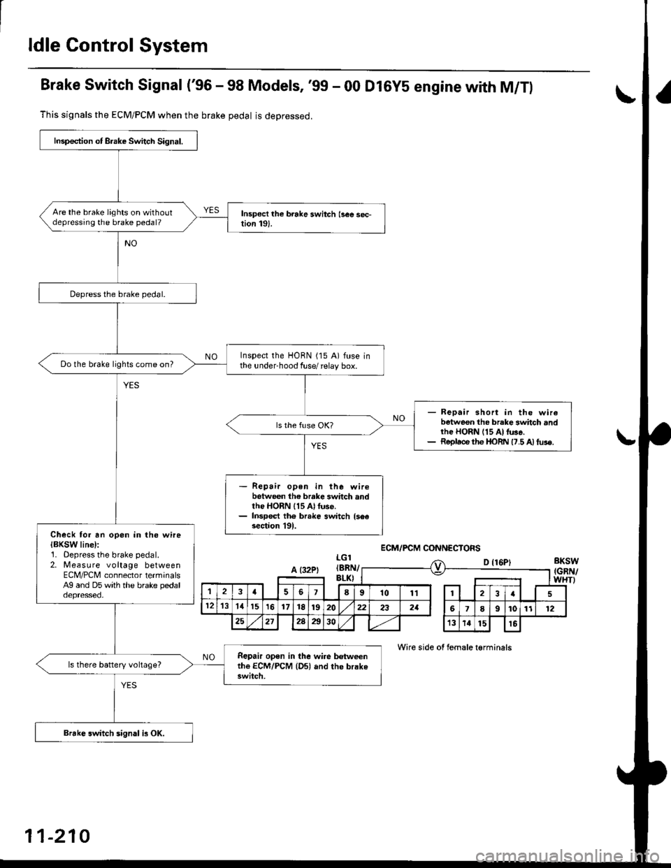
Brake Switch Signal ('96 - 98 Models, '99 - 00 Dl6YS engine with M/Tl
This signals the ECM/PCM when the brake pedal is deoressed.
LGlBKSW(GRN/WHTI
D {16P)
Wire side of female t€rminals
Inspection of Brake Switch Signal.
Are the brake lights on withoutdepressing the brake pedal?
Depress the brake pedal.
Inspect the HORN (15 A) fuse inthe under-hood fuse/ relay box.Do the brake lights come on?
- Repair short in the wirebetween the brake 3whch andrhe HORN 115 At lu3e.- Replace the I|oRN 17.5 A) tus€.
Repair open in the wirebetween the brake switch andthe HORN 115 Al fuse.Inspect th6 br.ke switch {s6€section l9l.Check tor an open in the wireIBKSW line):1. Oepress the brake pedal.2. Measure voltage betweenECM/PCNI connector terminalsAg and D5 with the brake pedaloepresseo.
Repair open in the wire b€tweenthe ECM/PCM {Dsl and the brakeswitch.
ls there battery voltage?
Brakc switch sign.l is OK.
ECM/PCM CONNECTOFS
A (32PtIBRI\v
,la678101112I
121311151617t8192022232aI9101112
25212Aa3013141516
11-210
Page 481 of 2189
ldle Control System
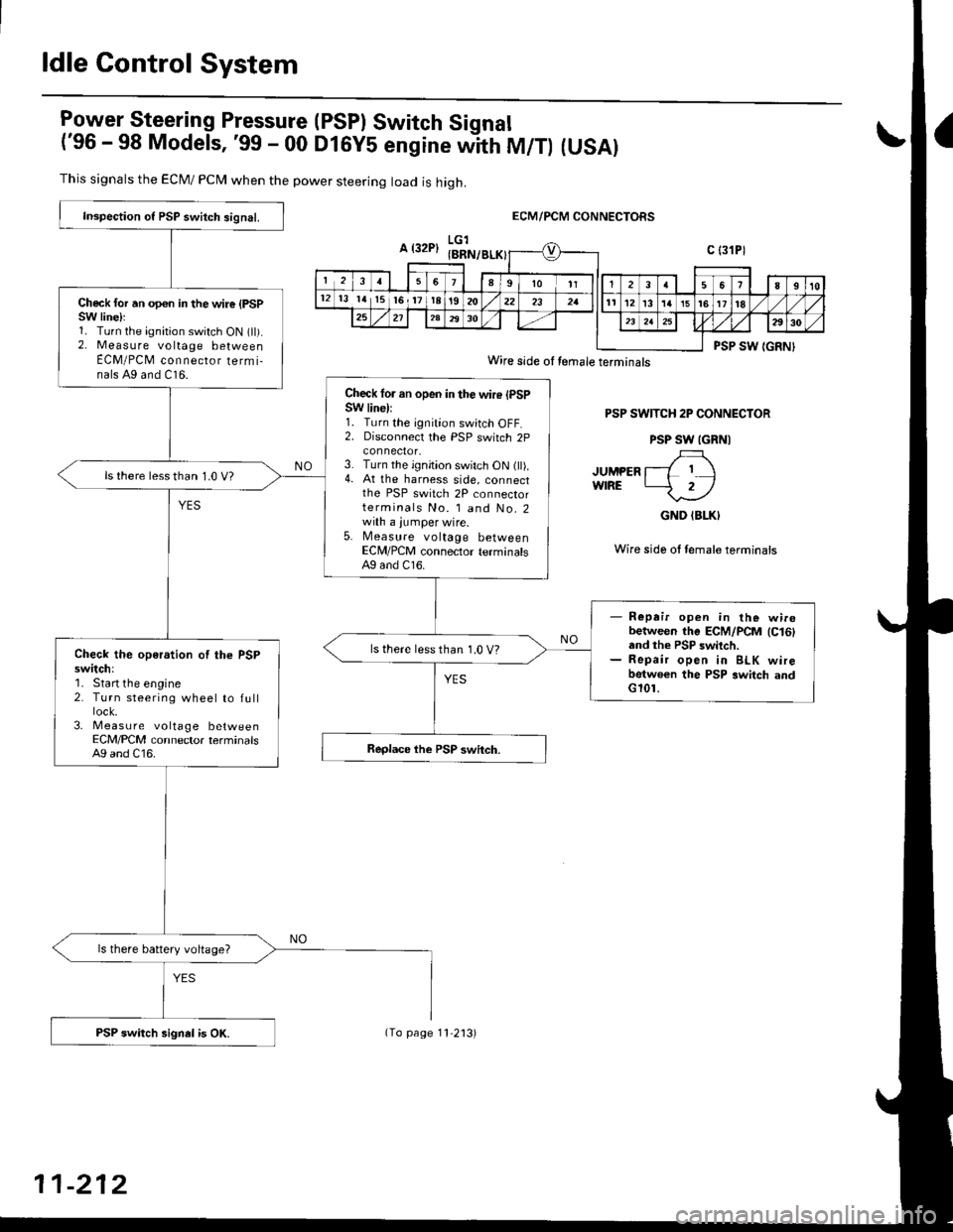
lgy"t9!"_"ring Pressure (PSPI Switch Signal
('96 - 98 Models, '99 - 00 DlGy5 engine witn fU/f) (USAI
This signals the ECM/ PCN4 when the power steering load is high.
ECM/PCM CONNECTORS
PSP SWITCH 2P CONNECTOR
PSP SW IGRNI
JUMPER l--L I IwfRE -2/
GND (BLKI
Wire side ol female terminais
Inspection o{ PSP switch signal.
Check for an opon in the wire {PSPSW linelr1. Turn the ignition switch ON (ll).2. Measure voltage betweenECM/PCM connecror termi-nals A9 and C16.
Check lor an open in the wire (PSPSW line):1. Turn the ignition switch OFF.2. Disconnecl the PSP switch 2p
3. Turn the ignition switch ON (ll).4. At the harness side, connectthe PSP switch 2P connectorterminals No. l and No.2with a jumper wire.5. Measure voltage betweenECM/PCM connector terminalsAg and C16.
ls there lessthan 1.0 V?
- Repair open in the wirobetween the ECM/PCM lc16land the PSP switch.- Repair open in BLK wirebetwoen the PSP switch andG101.
ls there less than 1.0 V?Check the operation of the PSPswitch:'1. Start the engine2. Turn steering wheel to full
3- Measu re voltage betweenECM/PCM connector terminalsA9 and C16.
ls there battery voltage?
PSP switch signel is OK.
Wire side oI temale terminals
11-212
(To page 11'2'13)
Page 483 of 2189
ldle Control System
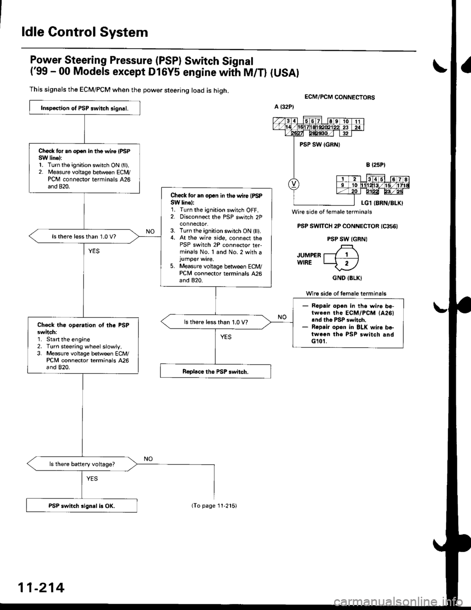
Power Steering Pressure (PSP) Switch Signal
('99 - 00 Models except Dl6y5 engine with M/T) (USAI
This signals the ECM/PCM when the power steering load is high.
Wire side of female terminals
PSP SWTTCH 2P CONNECTOR (qts6)
PSP SW (GRN)
JUMPER T---7 1 \wlRE LJ- 2-l
GND IBLK)
Wi16 sid6 of temale terminals
ECM/PCM CONNEgTORS
Inspoction ot PSP switch signal.
Check for an op€n in the wire (PSPSW linel:1. Turn the ignition switch ON (ll).2. Measure voltage between ECN4/PCM connector terminals 426and 820.
Check for .n open in tho wire IPSPSW line):1. Turn the ignition switch OFF.2. Disconnoct the PSP switch 2Pconnector.3. Turn the ignition switch ON (ll).4. At the wire side, connect thePSP switch 2P connector ter-minals No. 1 and No.2 with ajumper wire.5. Measure voltage between ECM/PCNI connoctor terminals 426and 820.
ls there lessthan 1.0 V?
- Ropai. opgn in ths wire be-tw.€n the ECM/PCM {A261rnd th6 PSP switch.- Ropsir opon in BLK wi.o bo-twoen tho PSP switch andG101.
ls there less than 1.0 V?Check the operation ot the PSPsw;tch:'1. Start the engine2. Turn steering wheelslowly.3. Measure voltage between ECM/PCM connector terminals 426and 820.
ls there battery voltage?
PSP switch sign8l i3 OX.
11-214
(To page 11-215)