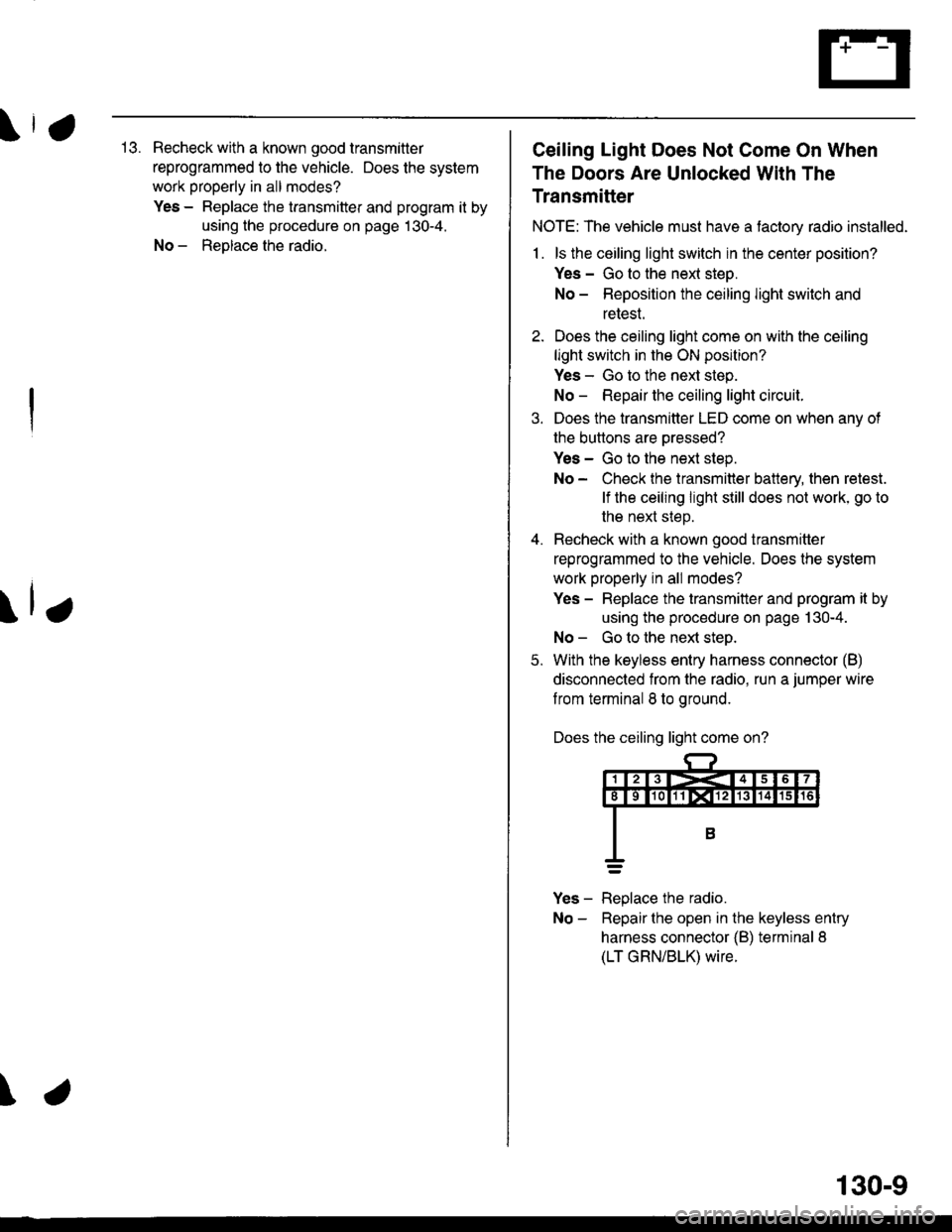
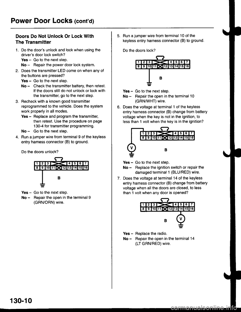
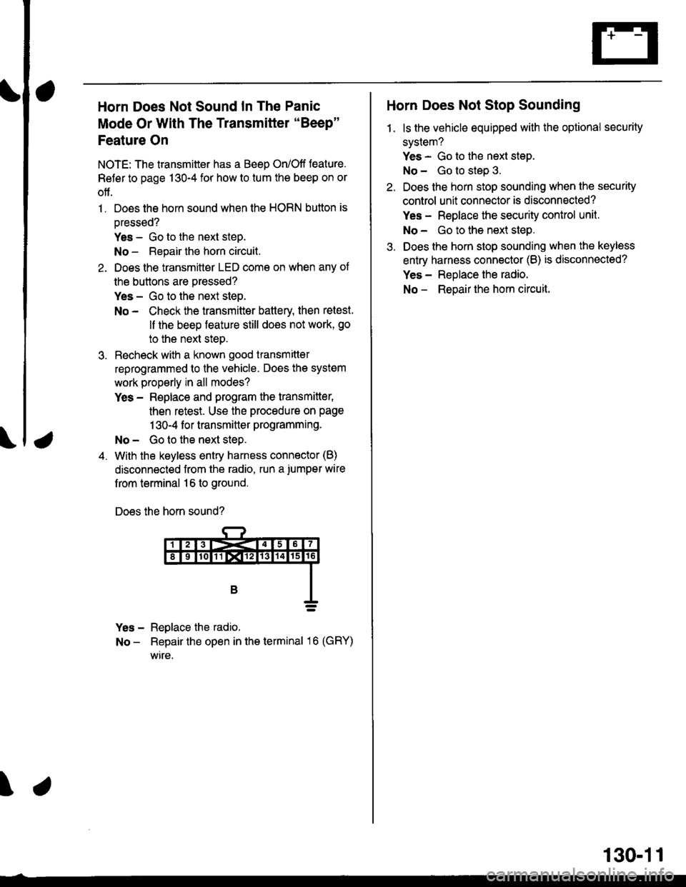
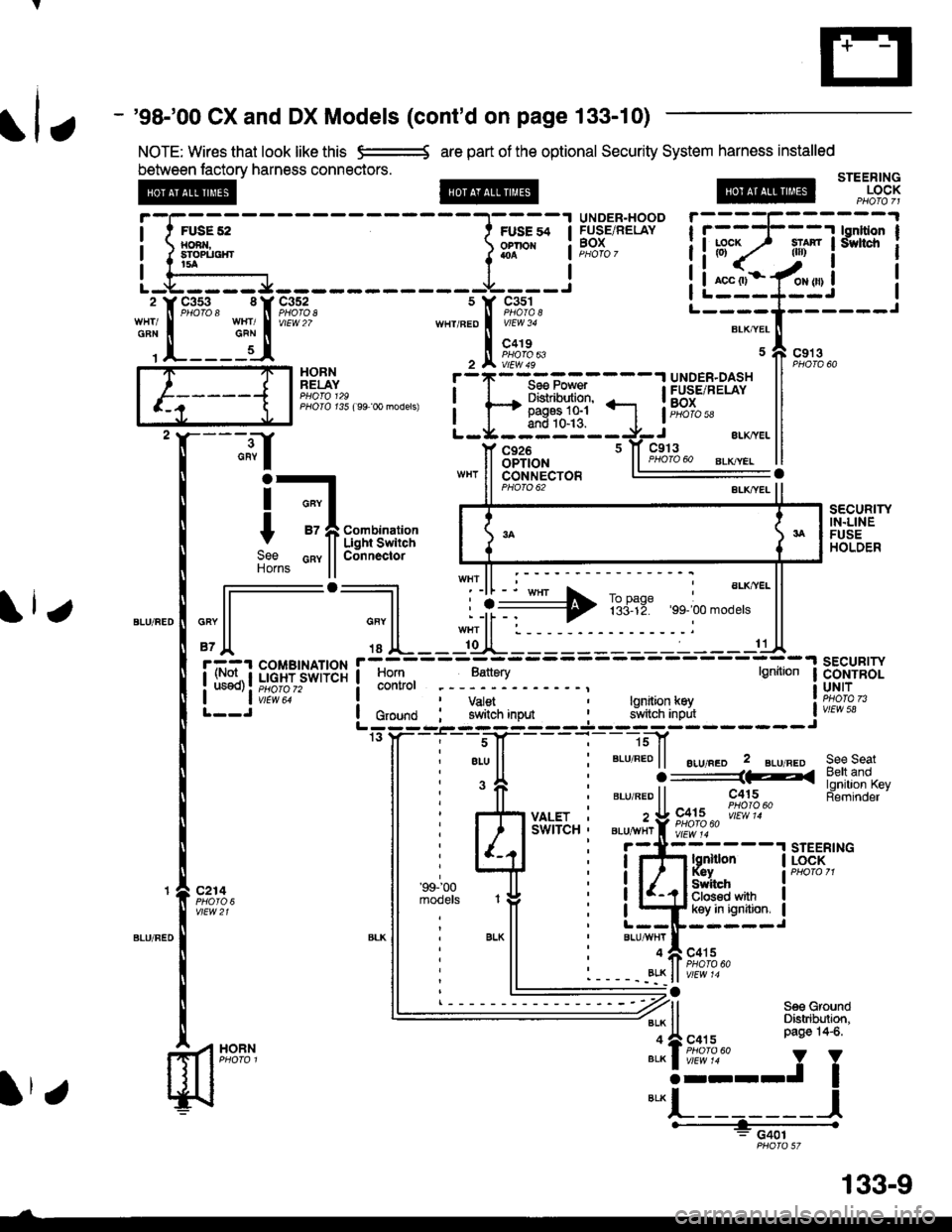
Page 1837 of 2189
- Under-hood ABS Fuse/Relay Box
Fuse
Number
(To underhood ABS fuse/relay box w re harness)
ABS pump motor
| 10-14 I ABS control unit
i ABS control unit
component or circuit ProiectedFuse Name
PUMP MOTOR
I ABS +B
ABS PUMPMOTOR RELAY(To main wire harness)
(To rnain wlre harness)
I!,ITR CHECK
6.3
Page 1838 of 2189
Fuse/Relay Information lcont'd)
- Under-hood Fuse/Relay Box
Front View
T'102(To engine wire harness)
LO
T1Oo starter cables)
*: Not Used
Rear View
c353To main wire harness
DE
tr
tr
tr
t-l
IJ
n
tJ
t-l51
IJ
n
IJ
n5T
IJ
[[o main wire harness)
6-4
ffo main wire harness)fto main wire harness)
Page 2002 of 2189
Fog Lights
_ Vehicles pre'wiredfor accessorysecurity system
SECURITY SYSTEMCONNECTOR(oPT|ON)
"!'19*13*
u,.*,"
a
c403
----.t COMB|NAT|ON
: swrrcHI PHOIOT2
lvtEw u
I
I
FOG LIGHTIN-LINE FUSE
FUSFI H,'lt.cw 8llaa
BLKI .--<
t_G2O2
gee GroundDistribution,pag€ 144.
i t-' BsJ:?'tr! li[?i,i'*'LJ------J
_ _tlI',-Yfi::"* *,*,,
a,
ot'
tttr(
---g-----J _- -"il( - see H€dbnt
;eo'q;r. I-) oaoe loo.
See Headlights '(Canada)
l-l 1 aeomnr
k-j'/,-dl15 llJ - - oplronal Fog Light swttch Harness - - -.I UNOER.DASH
I FUSE/RELAY
FUSE2l I BOx
R H/r- i PHoro 5errow BEA
I
---!':--J--1frf':l,"
i::.,.n.*BEo,naHT I !7
*':#i,!J
^ L--8-
i33o,,nno t f-
"-'-:E+
1 10-10
Page 2031 of 2189

\,113. Recheck with a known good transmitler
reprogrammed to the vehicle. Does the system
work properly in all modes?
Yes - Replace the transmitter and program it by
using the procedure on page 130-4.
No - ReDlace the radio.
\lr
\
Ceiling Light Does Not Come On When
The Doors Are Unlocked With The
Transmitter
NOTE: The vehicle must have a tactory radio installed.
1 . ls the ceiling light switch in the center position?
Yes - Go to the nexl steo.
No - Reposition the ceiling light switch and
retest.
2. Does the ceiling light come on with the ceiling
light switch in the ON position?
Yes - Go to the next step.
No - Repair the ceiling light circuit.
3. Does the transmitter LED come on when anv of
the buttons are oressed?
Yes - Go to the next step.
No - Check the transmitter battery, then retest.
lf the ceiling light still does not work, go to
the next steD.
4. Recheck with a known good transmitter
reprogrammed to the vehicle. Does the system
work properly in all modes?
Yes - Replace the transmitter and program it by
using the procedure on page 130-4.
No - Go to the ne)d steo.
5. With the keyless entry harness connector (B)
disconnected from the radio. run a jumper wire
f rom terminal 8 to ground.
Does the ceiling light come on?
Yes - Replace the radio.
No - Repairthe open in the keyless entry
harness connector {B) terminal 8
(LT GRN/BLK) wire.
130-9
Page 2032 of 2189

Power Door Locks (contd)
Doors Do Not Unlock Or Lock With
The Transmitter
1. Do the door's unlock and lock when usinq the
driver's door lock switch?
Yes - Go to the next step.
No - Repair the power door lock system.
2. Does the transmitter LED come on when anv of
the buttons are oressed?
Yes - Go to the next steo.
No - Check the transmitter battery, then retest.
It lhe doors still do not unlock or lock with
the transmitte( go to the next step.
Recheck with a known good transmitter
reprogrammed to the vehicle. Does the system
work properly in all modes.
Yes - Replace and program the transmitter,
then retest. Use the procedure on page
1 30-4 f or transmitter programming.
No- Gotothe next step.
Run a jumper wire from terminal I of the keyless
entry harness connector (B) to ground.
Do the doors unlock?
Yes - Go to the next steD.
No - Repair the open in the terminal 9
(GRN/ORN) wire.
130-10
5. Run a jumper wire from terminal 10 ol the
keyless entry harness connector (B) to ground.
Do the doors lock?
ves - Go to ttie next steo.
No - Repair the open in the terminal 10
(GRN/vVHT) wire.
Does the voltage at terminal 1 of the keyless
entry harness connector (B) change from battery
voltage when the key is not in the ignition, to
less than 1 volt when the key is in the ignition?
7.
Yes - Go to the next step.
No - Replace the ignition switch or repair the
damaged terminal 1 (BLU/RED) wire.
Does the voltage at terminal 14 of the keyless
entry harness connector (B) change from battery
voltage when all the doors are closed, to less
than 1 volt when any door is opened?
Yes - Replace the radio.
No - Repair the open in the terminal 14
(LT GRN/RED) wire.
Page 2033 of 2189

a
Horn Does Not Sound In The Panic
Mode Or With The Transmitter "Beep"
Feature On
NOTE: The transmitter has a Beep On/Off feature.
Refer to page 130-4 for how to tum the beep on or
off.
1. Does the horn sound when the HORN button is
oressed?
Yes - Go to the next steD.
No - Repair the horn circuit.
2. Does the transmittor LED come on when any of
the buttons are pressed?
Yes - Go to the next step.
No - Check the transmitter battery then retest.
ll the beep feature still does not work, go
to the next steo.
3. Recheck with a known good transmitter
reprogrammed to the vehicle. Does the system
work properly in all modes?
Yes - Replace and program the transmitter,
then retest. Use the procedure on page
1 30-4 f or transmitter programming.
No - Go to the next step.
4. With the keyless entry harness connector (B)
disconnected from the radio, run a.iumper wire
f rom terminal 16 to ground.
Does the horn sound?
Yes - Reglace the radio.
No - Repair the open in the terminal 16 (GRY)
wire.
\
Horn Does Not Stop Sounding
1. ls the vehicle equipped with the optional security
system?
Yes - Go to the next step.
No - Go to step 3.
Do€s the horn stop sounding when the security
control unit connector is disconnected?
Yes - Replace the security control unit.
No- Go to the next step.
Does the horn stop sounding when the keyless
entry harness connector (B) is disconnected?
Yes - Reolace the radio.
No - Reoair the hom circuit.
130-11
Page 2050 of 2189
Security System (cont'd)
- '96-'97 CX and DX Models (cont'd on page 133-10)
NOTE: Wires that look like this e:=---{ are pan of the optional Security System harness installed
between factorv harness connectors.
@
FUSE 52toRr{,sTorlrotirt5a
STEERINGLOCK
c20'lPHO|O 23vtEw 3a
HORNRELAY
".,,".:J[--
'I
"""'
[*u""''"h
GAY
GRY
.--.tf
rv lla:
"ll
114 H(al c(.-t
+
)e florns
Horn RelayConnecto.
sEcuRrwIN.LINEFUSEHOLDER
ALK,YEL
11
Horn Batiary lgnitionSECURITYCONTROLUNIT
vtEw 58
c214
vtEw21
/1H?#,
See Seat BeltO ___________1F_( ano ronrl|on
".u "eo ll c415 KeY Reminder
" U c+ts 'i!,1fl0
eLu,,,viiY ll9,'9.60
BLU/FED
BLK
gd!ryi--],.,,.*,"o
ilnffi"* !"*"
I L+ kev In ignition. IL--ll------J"'utTf,
"o',uoLK ll PHofo46a
G401
"",,""i"1---"-",-,""rf &f,.f,,,
t A-----1.:A Ho'n Reray
ll ll Connector"""o"n
ll
*""T
ll1A-------/{
r-------'l lonltion I
iltr? _ili* !'"*' i
!i*.1-/*.,i !I L---*--J It--"-.*-*t------J
uAcgtar-x,ver" ll eroro oo
133-8
Page 2051 of 2189

V
- '98-'00 CX and DX Models (cont'd on page 133-10)
NOTE: Wires that look like this e=-* are part of the optional Security System harness installed
between lactory harness connectors.STEERINGLOCK
UNOER-HOODFUSE/RELAYBOX
HORNRELAY
PHOIO t35 ( 99 0o models)
;.;l
HOBN
c926OPTION
i-t
t -fii;r,'im:";
9"" cnv llConnectorHorns ll
PHO|O 62
sEcuRrwIN.LINEFUSEHOLDER
,"" l-l--';] L ii+ TBriE:,, ;.'".*"' ll
'Jl '' lL--l[JL---:-----------C
i. rl::t ;;;[.?jsor+3r i
lff],
-,
;,:"1.
- . :-
- -
;_:
- - -
tt*
I ii}"*:*'t--J'''*uo lc,o,na i Y#,iln,"o* i 9JlflB'],iff, iw,E"L:;; -'- ---J ---.l.--- -J------- Jrs y- - -i'. - -s-J[- - - -
l-
- ]sf
ll ; eLu ll ' BLU REo | | ".r,".o 2 gLu neo see seat
i 'fi i ".,".oii----iiiu
-
[tJ.li'fll5"t
i r{i y*sr.. : z!9X;2""|"i!'}?.""
ll i l/rlu'-'u"i
"i-jttz---'rsrEER,
Fii;i," ll ;i'".'J^ ,# i iQffi*"it*"ll : ll L--IF-----J*-
ll
' BLK
ll i
"'u*TI
"o,u
' 11 ' --- --;' Bett and
SWITCH ' BLU^YHr f i;;;i;" l{ -l-'- ' -';r{iss"-
STEERTNG
, r atv r- lt PHofo 60. - - - -. _8!K ll v/Ew '4
: G401
fl
-1[::_5J*nt
s Y c3s1
,n"r,".o I i[o"to,'
, tr ft?;","
liuF;lt"ls'rs?rl
iL:"::Ifui i'--T'Il,].----r
Itr
133-9