Page 1811 of 2189
\
6. Disconnect the connectors from the horn and cruise
control sevresume switches, then remove the steer-
ing wheel nut.
STEERINGNUT
CRUISE CONTROLSET/RESUMESWITCH CONNECTOR
)
HORN CONNECTOR
Remove the steerlng
pulrer.
CABLE REEL2P CONNECYOR
wheel using a steering wheel7.
STEERING WHEEL PULLEF
{Commerciallv_available)
)U
8. Remove the column covers.
Disconnect the 3P connector between the main wire
harness and cable reel sub-harness, 8nd the 2P con-
nector between the cable reel and SRS main harness'
CONNECTORHOLOER
SRS MAIN HARNESS2P CONNECTON
CABLE REEL SUBHARNESS3P CONNECTOR
10. Remove the cable reel from the column {cont'd}
24,73
--/
CABLE REEL
Page 1812 of 2189

Cable Reel
Replacement (cont'd)
11.
NOTE:
. Before installing the steering wheel, the front
wheels should be aligned straight ahead.. Be sure to install the harness wires so that theyare not pinched or interfering with other parts.. After reassembly. confirm that the wheels arestill turned straight ahead and that the steeringwheel spoke angle is correct (road test). lf minor
spoke angle adjustment is necessary, do so onlyby adjusting the tie-rods, not by removing andrepositioning the steering wheel.
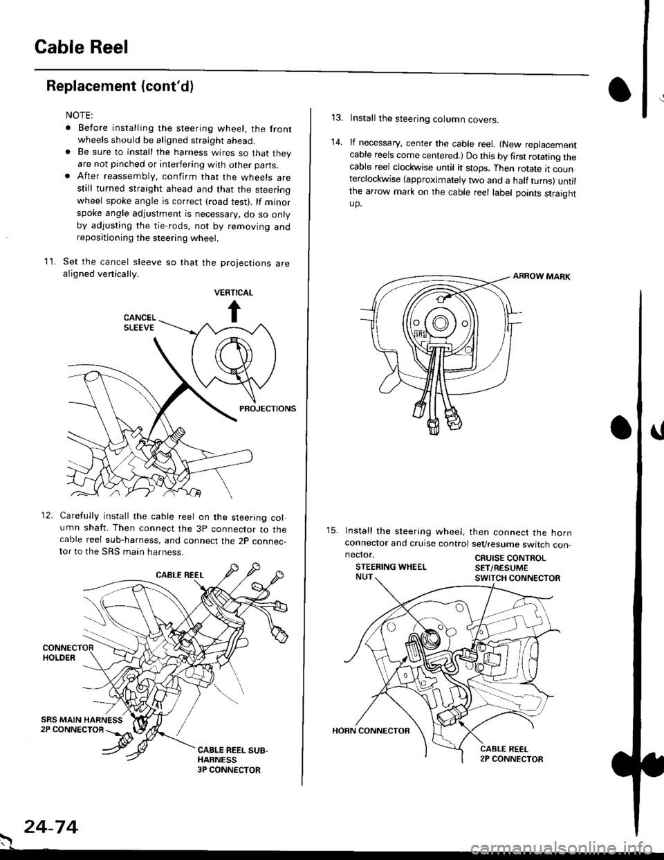
Set the cancel sleeve so that the projections arealigned venically.
PROJECTIONS
12. Carefully install the cable reel on the steering column shaft. Then connect the 3p connector to thecable reel sub-harness, and connect the 2p connec-tor to the SRS main harness.
. 24-74
Install the steering column covers.
lf necessary, center the cable reel. {New replacementcable reels come centered.) Do this by first rotating thecable reel clockwise until it stops. Then rotate tt counterclockwise (approximately two and a half turns) untilthe arrow mark on the cable reel label points straightup.
ARROW MARK
15. lnstall the sleering wheel, then connect the hornconneclor and cruise control sevresume switch con
14.
neclor.
STEERING WHEELCRUISE CONTROLSET/RESUM€
Page 1813 of 2189

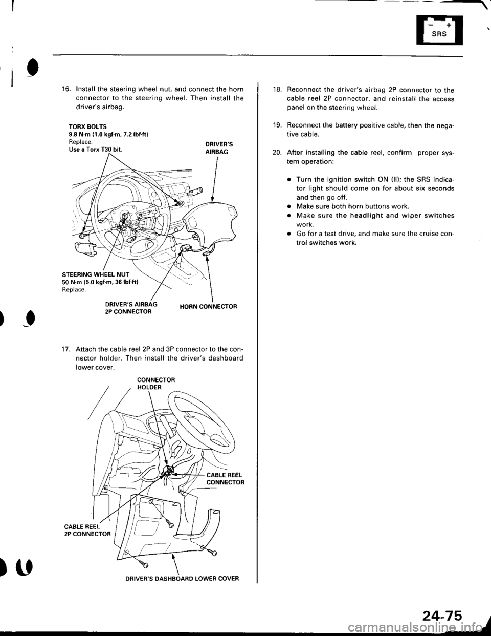
16. Install the steering wheel nut, and connect the horn
connector to the steering wheel. Then install the
driver's airbag.
TORX SOLTS9.8 N m 11.0 kgf m, 7.2 lbtftlReplace.Use a Torx T30 bit.
STEERING WHEEL NUT50 N.m 15.0 kgf.m,36lblft)Replace.
DRIVEB'SAIRBAG
DRIVER'S2P CONNECTOBHORN CONNECTOB
I
17.Attach the cable reel 2P and 3P connector to the con-
nector holder. Then install the driver's dashboard
lower cover.
)UDRIVER'S DASHBOARD LOWER COVER
24-75
18. Reconnect the driver's airbag 2P connector to the
cable reel 2P connector. and reinstall the accesspanel on the steering wheel.
19. Reconnect the battery positive cable, then the nega-
tive cable.
20. After installing the cable reel, confirm proper sys-
tem operation:
Turn the ignition switch ON (ll); the SRS indica-
tor light should come on for about six seconds
and then go off.
Make sure both horn buttons work.
Make sure the headlight and wiper switches
Go for a test drive, and make sure the cruise con
trol switches work.
a
a
Page 1814 of 2189

SRS Unit
Replacement
CAUTION:
. Betore disconnoqting lny pErt of the SRS wire hal-ness, disconnect th9 airbag conn"ctorlsl.. During installltion or teplacemsnt. do not bump(impact w.cnch, hamm€r stc.l the area noar tho SRSunit.
NOTE:
o Do not damage the SRS unit terminals or connectors.. Do not disassemble the SRS unit; it has no service-able parts,
. Store the SRS unit in a clean, dry a.ea,. Do not use any SRS unit which has be€n subjected towater or shows signs of being dropped or improperlyhandled. such 8s dents, cracks or deformation.
1. Disconnect the bsttery negative cable. then discon-nect the positive cable from the battery, and wait atleast three minutes.
2. Disconnect the airbag connector{s}:
NOTE: When disconnected, the airbag connector isautomatically shorted,
Driver's Side:
. Remove the access panel from the steering wheel.then disconnect the 2P connector between the driv_er's airbag and cable reel (see page 24-11).
Front Passenge/s Side:. Disconnect the 2P connector between the tront oas_senger's airbag and SRS main harness (see page 24-11).
24-76
o\
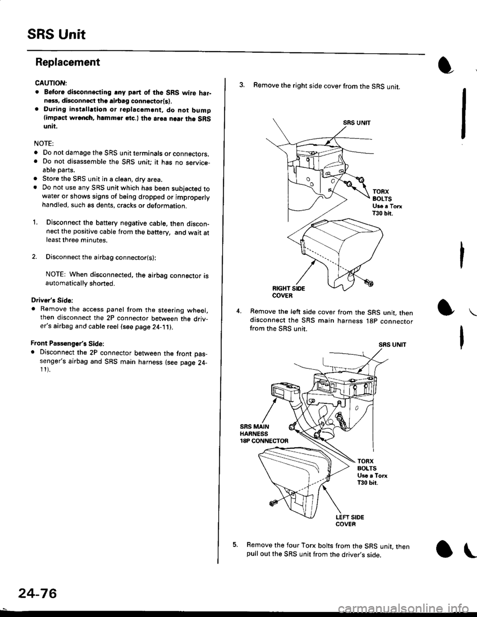
3. Remove the right side cover from the SRS unit.
SRS UNTT
TOBXBOLTSUge a TorxT30 bit.
RIGHT SIOE
Remove the left side cover from the SRS unit, thendisconnect the SRS main harness lgp connectorfrom the SBS unit.
SRS UNIT
5. Remove the four Torx bolts from the SRS unit, thenpull out the SRS unit from the driver,s side,
COVER
Page 1815 of 2189
6. Install the new SRS unit.
NOTE: Do not reuse a torx bolt that has red
threads. Replace the bolt with a new one.
)
7.
TORX BOLTS9.8 N.m l'1.0 kg{.m, 7.2 lbf.ft}Use a Torx T30 bit.
Connect the SRS main harness l8P connector to the
SRS uniu push it into posjtion until it clicks.
Install the SRS unit covers (ri9ht and left). Make
sure the covers snap together in the middle.
8.
TORX BOLTS9.8 N.m 11.0 kgf.m, 7.2 lbf.ft)U3e . Torx T30 bit.
SRS MAIN HARNESS
)(l
9.
10.
't2.
Reconnect the driver's aibag 2P connector to the
cable reel 2P connector, then reinstall the access
panel on the steering wheel.
Reconnect the tront passenger's airbag connector
to the SRS main harness.
Reconnect the battery positive cable, then the nega
tive cable.
After installing the SRS unit, confirm proper system
operation: Turn the ignition switch ON (ll); the SRS
indicator light should come on for about six seconds
and then go oif.
11.
24-77
.-
Page 1817 of 2189

Contents
How to Use This Manual ICircuit Schematics (see Circuit Index)Fuse/Relaylnformation 6Ground-to-Componentslndex 6-6ComponentLocationPhotooraohs 201Conriector Views 202
Circuit Index
Accessory power socket 155Air conditionerAir delivery'96198 models 61'99-'00 models 61-2Blower controls'96198 models 60'99100 models 60-1Compressor controls 62Fans 63Anti-lock brake system (ABS) 44A/T gear position indicatorCVT 89All except CVT 89-1Automatic transmission controlsAll '96-'98 models except CVT and GX 39All '99100 models except CVT 39-8All GX models 39-8'96-'�98 CVT 39-4'99100 cw 39-12Back-up lightsCoupe and Sedan 110Hatchback l'10-1Brake lightsAll Coupes and'96-'98 Sedans 110-15'99-'00 Sedans 110-16Hatchback 110-17Brake system indicator light'96198 models 7'1'99100 models 71-1Ceiling light 114-3Charging system 22Condenser fan 63Console lights 114Cruise control 34Dash lights 114Daytime running lights 110- 13Engine coolant temperature gauge 81-1Fog lights 110-10Front parking lights 110-2Fuel gauge 81-1Fuse/relay boxUnder-dash 6Under-hood 6-4Underhood ABS 6-3Gauges 81Ground distribution 14Ground-to-Componentslndex 6-6Hazard warning lightsAll except '99100 Sedans 110-6'99100 Sedans 110-8Headlights 110-12Headlight switch 100Heater - See Air ConditionerHorn'96197 models 40'98 model 40-1'99100 models 40-2lgnition key reminder 73lgnition systemAll '96198 models except Dl685 20All '99100 models except D16Y5 with Mn 2O-2All D1685 engines 20-2'99-'00 D 16Y5 with M/T 20
lndicators 80Integrated control unit 70lnterlock systemAll except'96J98 CVT 138'96198CVT 138-1License plate lightsAll Coupes and '96-'98 Sedans I l0-3'99100 Sedans 1 10-4Hatchback 110-5Low fuel indicator light 74Moonrool'96197 models |22'98-'00 models 122-1Odometer 81Oil pressure indicator light 80-3Power distributionBattery to ignition switch, fuses, and relaysFuses to relays and components 10-2Power door locksAll models without keyless entry 130'96-'98 models with keyless entry 130-2'99100 models with keyless entry 130-12Power mirrorsWithout detogger 141With defogger '141-2
Power windows 120Programmed fuel injection system (PGNr-Fl)All '96-98 models except D1685 23All '99-'00 models except D16Y5with M/T and D1685 24All D1685 engines 25'99100 D16Y5 with M/T 23Radiator fan 63Rear window defogger'96-,98 models 64'99100 models 64-1Seat belt reminder 73Security system'96.'98 USA HX, LX, EX 133'96-'98 Canada EX, Si 133'99TOO USA HX, LX, EX, DX.V Si 133-4'99100 Canada EX, Si 133-4All CX and DX models 133-8Speedometer 81Starting systemA./T (All except Dl685) 21A"/r (D16Bs) 21-1Manualtransmission 21-2Slereo sound system 150Supplemental rastraint system (SRS) 47Tachometer 81TailliqhtsAllboupes and'96-'98 Sedans 110-3'99100 Sedans 1 10-4Hatchback 110-5Trunk light 114-3Turn signal lightsAll except'99100 Sedans 110-6'99-'00 Sedans 1 10-8Vehicle speed sensor (VSS) 33Wiper/washerFront 91Rear 92
10
Page 1834 of 2189
![HONDA CIVIC 1999 6.G Workshop Manual Fuse/Relay Information
- Under-dash Fuse/Relay Box
Front View
c712(To moonroof wire harness)
. : Canadai : Not UsedO : C926 loprion (+B)l
@ : C927 loption (dash lights)]
O : C928 [Option (ACC]I
@ : C9 HONDA CIVIC 1999 6.G Workshop Manual Fuse/Relay Information
- Under-dash Fuse/Relay Box
Front View
c712(To moonroof wire harness)
. : Canadai : Not UsedO : C926 loprion (+B)l
@ : C927 loption (dash lights)]
O : C928 [Option (ACC]I
@ : C9](/manual-img/13/6068/w960_6068-1833.png)
Fuse/Relay Information
- Under-dash Fuse/Relay Box
Front View
c712(To moonroof wire harness)
. : Canadai : Not UsedO : C926 loprion (+B)l
@ : C927 loption (dash lights)]
O : C928 [Option (ACC]I
@ : C929 loption (lc2)l
Rear View
css2
c421(To main wire harness)
c801CI-o SRS main harness)
c501(To dashboard wire harness)
^ : Not used ('96-'97 models)
c913(To ignition switch)
INTEGRATEDCONTROL UNITCONNECTOR A
c419Oo main wire harness)
REAR WINDOWDEFOGGER RELAY
TURN SIGNAUHAZARD RELAY
c423(To main wire harness)
co
c422(To main wire harness)
POWERwtNDowRELAY
c551flo lloor wire harness)c439 f96.'97 MODELSand ALL GX MOOELS)(To main wire harness)
T1 T-t T"l T"t r-r r-'l T1 F n r-l r-l r'123 24 25 26 27 28 29 30 31 32 33I-J I.J I.J IJ IJ IJ LJ IJ IJ I.J I.J I-I
r"1 r-t r-t T-l r"l r-r Fl r:1 n rJ n -12 13 14 t5 16 17 t8 19 2A 2t 22LI I.J L! LI tJ LJ (J LI IJ IJ T-I I.J
n r:l rj.l |-l T"l Tl r:t n r-l |;.l r-r r-l1 2 3 4 5 6 7 I 9 10 11LI LI IJ LJ LJ I,J T-I I.J TJ IJ I.-I tJ
c420(To main wire harness)
6
(To floor wire harness)
Page 1835 of 2189

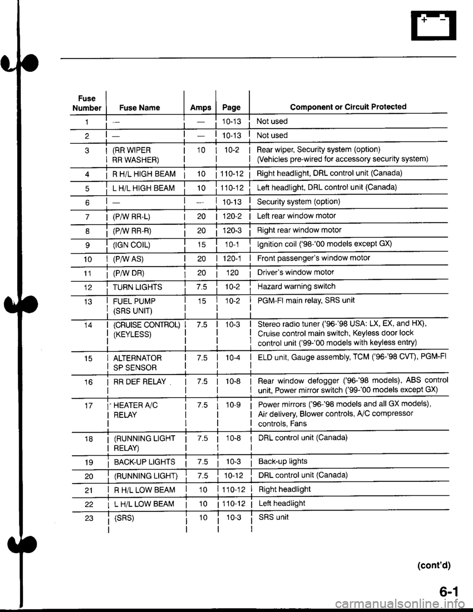
Fuse
NumberAmpsPageFuse Name
(RR WIPER
RR WASHER)
i R HiL HIGH BEAM | 10
L H/L HIGH BEAM
| (PAIV RR-L)
i (P/vv RR-R)
(rGN CO|L)
10I (P,^/V AS)
Component or Circuit Protected
Not used
Not used
Rear wiper, Security system (option)
(Vehicles pre-wired for accessory security system)
'10r 1n-2
I
| 1 10-12i Right headlight, DRL control unit (Canada)
Lett headlight, DRL control unit (Canada)
I ro-rsSecurity system (option)
| 120-2 | Left rear window motor
Right rear window motor
lgnition coil ('98-'00 models except GX)
| 120-1 | Front passenger's window motor
i (PiW DH)| 20 1 12O I Driver's window motor
TURN LIGHTSHazard warning switch
FUEL PUMP
(SRS UNIT)
PGM-FI main relav, SRS unit
(cRUrsE CoNTROL)
/KtrVt trSS\
Stereo radio tuner ('96-'98 USA: LX, EX, and HX),
Cruise control main switch, Keyless door lock
control unit ('99-'00 models with keyless entry)
15ALTERNATOR
SP SENSOR
l-a10-4I ELD unit, Gauge assembly, TCM (96-'98 CW, PGM-FI
16I RR DEF RELAY7.510-8I Rear window defogger ('96-'98 models), ABS control
I unit. Power mirror switch ('99-'00 models except GX)
i-HEATER r/C
I RELAY
Power mirrors ('96-98 models and all GX models),
Air delivery, Blower controls, AilC compressor
controls, Fans
I (RUNNING LIGHT
I RELAY)
1 7.5 1
tl
I DRL control unit (Canada)
i BACK-UP LTGHTSi Back-up lights
(RUNNING LIGHT)DRL control unit (Canada)
I R H/L LOW BEAM'10 l11o-12Right headlight
I L H/L LOW BEAM | 101110-12 | Left headlight
(cont'd)
(SRS)SRS unit
6-1