Page 206 of 2189

Main Bearings
4.
Glearance
1.To check main bearing-to-journal oil clearance.
remove the main caps and bearing halves.
Clean each main journal and bearing half with a
clean shop towel.
Place one strip of plastigage across each main jour-
na l.
NOTE: lf the engine is still in the car when you bolt
the main cap down to check clearance, the weight
of the crankshaft and flvwheel will flaften the plasti-
gage further than just the torque on the cap bolt.
and give you an incorrect reading. For an accurate
reading, support the crank with a jack under the
counterweights and check only one bearing at a
time,
Reinstall the bearings and caps, then torque the
bolts.
lst step: 25 N'm (2.5 kgl'm. 18 lbf'ft)
FinalsteD:
B16A2 engine:
76 N.m (7.8 kgf.m, 56 lbf'ft)
D16Y5, Dl6Y7, D16Y8 engines:
51 N.m (5.2 kgf'm, 38 lbf'ft)
NOTE: Do not rotate the crankshaft during inspec-
tron.
Remove the cap and bearing again, and measure the
widest part ot the plastigage.
Main Boaring-toJournal Oil Clearance:
816A2 engine:
Standald {New}:
No. l, 2, 4, 5 Journals:
O.O2,l - 0.042 mm 10'00(B - 0.0017 in)
No. 3 Journals:
0.030 - 0.048 mm {0'0012 - 0'0019 in)
Servico Limit: 0.06 mm {0.002 in,
Dl6Y5, Dl6
r, Dl6Y8 engines:
Standard (Nsw):
No. 1,5 Journals:
0.018 - 0.035 mm {0.0007 - 0'001'[ in)
No. 2. 3, 4 Journals:
0.02,1 - 0.0,(2 mm {0'0009 - 0.0017 in}
Service Limit: 0.05 mm (0.002 in)
\
7-9
7.
lf the plastigage measures too wide or too narrow,
(remove the engine if it's still in the car), remove the
crankshaft, and remove the upper half of the bear-
ing. Install a new. complete bearing with the same
color code {select the color as shown on the next
page), and rechsck the clearance.
CAUTION: Do nol fil€, shim, or scrape the bearings
or tho cap3 to adiust cleatanc€.
lf the plastigage shows the clearance is still incor-
rect, try the next larger or smaller bearing (the color
listed above or below that one), and check again
NOTE: lf the proper clearance cannot be obtained
by using the appropriate larger or smaller bearings,
replace the crankshaft and start over.
Page 207 of 2189

Main Bearing
Selection
CAUTION: lf the codes are indecipherable because of anaccumulation of dirt and dust, do not scrub them with a
wire brush or scraper. Clean them only with solvent ol
deiergent.
Crankshaft Bore Code Location
81642 engine:
Letters have been stamped on the end of the block as acode for the size of each of the 5 main journal bores.
Use them, and the numbers or bars stamped on the
crank {codes for main journal size), to choose the correct
beaflngs.
Main JournalCode Locations {Nombers or Barc)
Eearing ldentificationColor code rson lhe edge ofthe bear ng.Larger crank bore
acD
-----------""' Smallerbeanngtlhrcker)
9""1B':""
Alack
Black
Alue
7-10
\
D16Y5, D16Y7, D16Y8 engines:
Letters have been stamped on the end of the block as acode for the size of each of the 5 main journal bores.
Use them, and the numbers stamped on the crankshaft(codes for main journal size), to choose the correct bear-
Ings.
Main Journal Code Location (Numbers)
\
Color codeon theedge ofthe bearing-
Ldrger crank bore
Smaller bea ng {th'cker)
lr-l
t#lt+,tlf l 4 tlf '- 't
Smaller Smallermaan bearingjournal {thicker)
RedPinkGreen
PinkGreenBrown
GreenBrownBlack
GreenBrownBlackElue
I
Bearing ldentification
BcD
Page 208 of 2189

Connecting Rod Bearings
Clearance
Remove the connecting rod cap and bearing half
Clean the crankshaft rod iournal and bearing half
with a clean shop towel.
Place plastigage across the rod journal.
Reinstall the bearing half and cap, and torque the nuts.
Torque
Bl6A2 engine:
40 N.m (4.1 kgl.m, 30 lbf'ft)
Dr6Y5, D16Y7, D16Y8 enginss:
31 N'm (3.2 kgf.m, 23 lbf ftl
NOTE| Do not rotate the crankshaft during inspection.
Remove the rod cap and bearing half and measure
the widest part of the plastigage.
Connecting Rod Bearing-to.Journal Oil Glearance:
816A2 engine:
Standard lNewl: 0.032 - 0.050 mm
10.0013 - 0.0020 in)
Service Limit: 0.06 mm 10.002 inl
D16Y5, D16Y7, D16Y8 engines:
Standard lNew): 0.020 - 0.038 mm
(0.0008 - 0.0015 in)
Service Limit 0.05 mm 10.002 inl
'1.
4.
lf the plastigage measures too wide or too narrow'
remove the upper half of the bearing, install a new,
complete bearing with the same color code (select
the color as shown in the right column), and
recheck the clearance.
CAUTION: Do not lile, shim, or scrape the bearings
or the caps to adiust clgarance.
lf the plastigage shows the clearance is still incorrect.
try the next larger or smaller bearing (the color listed
above or below that one), and check clearance again.
NOTE: lf the Droper clearance cannot be obtained
by using the appropriate larger or smaller bearings,
replace the crankshaft and start over.
PLASTIGAGE STRIP
\
7.
7-11
Selection
CAUTION: lf the codes are indecipherable because of
an accumulation of dirt and dust, do not sclub them
with a wile brush or scraper. Clean them only with sol-
vent or detergent,
Connecting Rod Code Location
Numbers have been stamped on the side of each con
necting rod as a code for the size of the big end Use
them, and the letters stamped on the crankshaft (codes
for rod journal size), to choose the correct bearlngs
Half of number ls
stamped on bearingcap and the otherhalf is stamped onrod.
Bearing ldentilication
Color code is on theedge ofthe bearing.
lfA--;T] |
lle"'tt l;llcorlll ll
I lD;;ilril |l-l
Larger brg end bore
Smaller Smallerrod bearlngjournal (thicker)
---------------- Smallerbearing{thrcker)
RedPinkGreen
PinkGreen
GreenErownBlack
GreenBrownBlackBlue
1234
Connecting Rod Journal Code Locations (Lettels)
Page 209 of 2189
Pistons and Crankshaft
Removal
1. Remove the oil pan assembly.
2. Remove the right side cover.
816A2 engine
D16Y5, Dl6Y7, D16Y8 ongines
RIGHT SIDE
7-12
\
3. Remove the oil screen.
4. R€move the oil pump.
816A2 engin€
OIL SCREEN
D16Y5, D1oyr, D16Y8 engin.s
O-RINGReplace.
5, Remove the baffle plate (816A2 engine).
OIL PUMP
Page 210 of 2189

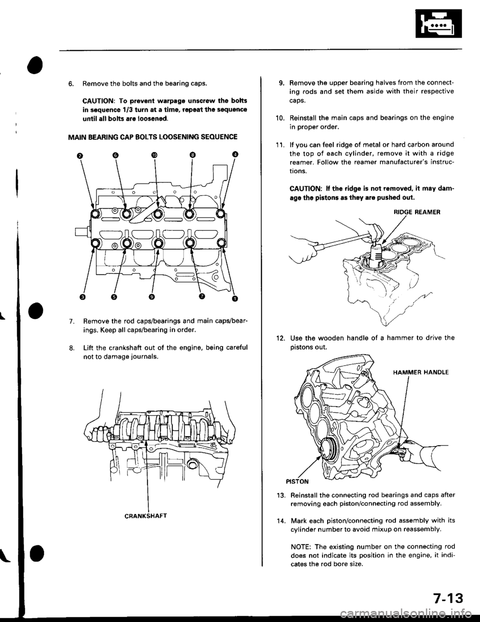
6. Remove the bolts and the bearing caps.
CAUTION: To prevenl warpago unscrow lhe bolts
in s€quence 1/3 turn at a tims, r€paat the soquence
until all bolts ar€ loo3ened.
MAIN BEARING CAP BOLTS LOOSENING SEOUENCE
Remove the rod caps/bearings and main capvbear-
ings. Keep all caps/bearing in order.
Lift the crankshaft out of the engine, being careful
not to damage journals.
7.
S:_]ILOJLOAO
CRANKSHAFT14.
7-13
qRemove the upper bearing halves from the connect-
ing rods and set them aside with their respective
caos.
Reinstall the main caps and bearings on the engine
in proper order,
lf you can feel ridge of metal or hard carbon around
the top of each cylinder, remove it with a ridge
reamer. Follow the reamer manufacturer's instruc-
I|ons.
CAUTION; lf the ridge is not removed, it may dam-
age tho pistons as they are pushod out.
RIOGE REAMER
10.
11.
12.Use the wooden handle of a hammer to drive the
pastons out.
13.Reinstall the connecting rod bearings and caps after
removing each piston/connecting rod assembly.
Mark each piston/connecting rod assembly with its
cylinder number to avoid mixup on reassembly.
NOTE: The existing number on the connecting rod
does not indicate its position in the engine, it indi-
cates the rod bore size.
Page 211 of 2189

Crankshaft
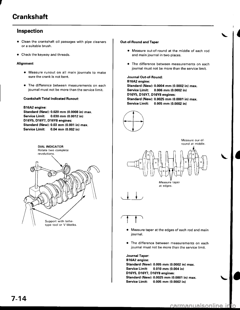
Inspection
. Clean the crankshaft oil passages with pipe cleaners
or a suitable brush.
. Check the keyway and threads.
Alignment
. Measure runout on all main journals to make
sure the crank is not bent.
. The difference between measurements on eachjournal must not be more than the service limit.
Crankshaft Total Indicated Runout:
Bl6A2 engine:
Standard (Newl: 0.020 mm {0.0008 in} max.
Service Limit: 0.030 mm {0.0012 inl
D16Y5, D15Y7, D15Y8 engines:
Standsrd {New): 0.03 mm (0.001 in} max.
Service Limit; 0.0i1 mm 10.002 in)
Support with lathetype tool or V blocks.
7-14
Out-of-Round and Tapet
. Measure out-of-round at the middle of each rod
and main journal in two places.
a The difference between measurements on eachjournal must not be more than the service limit.
Joulnal Out-of-Round:
81642 engine:
Standard (New): 0.0004 mm {0.0002 in) max.
Service Limit: 0.006 mm {0.0002 in)
Dr6Y5, Dl6Y7, D16Y8 engines:
Standard (Newl: 0.0025 mm (0.0001 inl max.
Service Limh: 0.005 mm (0.0002 inl
round at middle.
. Measure taper at the edges of each rod and mainjournal.
. The difference between measurements on eachjournal must not be more than the service limit.
JournalTaDer:
B16A2 ongine:
Standard lNewl: 0.005 mm (0.0002 inl max.
Service Limit: 0.010 mm (0.00i1 inl
D16Y5, D16Y7, Dl6YB engines:
Standard (New): 0.0025 mm {0.0001 in) max.
Service Limit: 0.005 mm (0.0002 in)
\
Page 212 of 2189

Pistons
Inspection
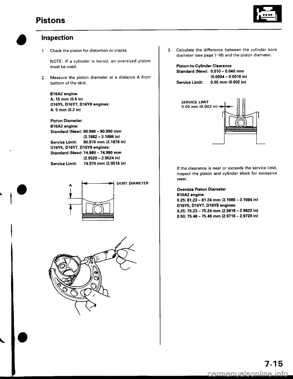
1.Check the piston for distortion or cracks,
NOTE: lf a cylinder is bored. an oversized piston
must be used.
Measure the piston diameter at a distance A from
bottom of the skirt.
816A2 engino:
A: 15 mm 10.6 in)
D16Y5, D16Y7, D16Y8 engines:
A: 5 mm (0.2 inl
Piston Diameter:
816A2 engine:
Standard lNewl: 80.980 - 80.990 mm
13.1882 - 3.1886 in)
Service Limit: 80.970 mm (3.1878 in)
D16Y5, D16Y7, D16Y8 engines:
Standard {New): 7,f.980 - 7i1.990 mm
|.2.9520 - 2.9521in!
Service Limit: 74.970 mm {2.9516 inl
SKIRT DIAMETER
57-1
3. Calculate the difference between the cylinder bore
diameter (see page 7-16) and the piston diameter.
Piston-to-Cylinder Clsarance
Standard lNewl: 0.010 - 0.0,10 mm
(0.0004 - 0.0016 inl
Servico Limit: 0.05 mm {0.002 in}
lf the clearance is near or exceeds the service limit,
inspect the piston and cylinder block for excessive
wear.
Oversizo Piston Diametor
816A2 ongine:
0.25t 81.23 - 81.21 mm (3.1980 - 3.1984 inl
D16Y5. D16Y7, D16Y8 engines:
O.25t 75.23 - 75.21 mm (2.9618 - 2.9622 in)
0.50: 75.i18 - 75.49 mm {2.9716 - 2.9720 in}
Page 213 of 2189

Cylinder Block
Inspection
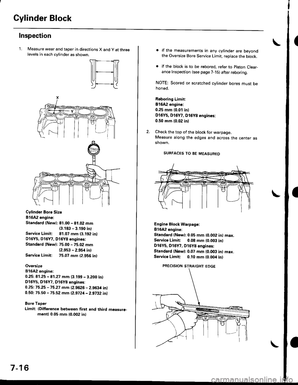
'LMeasure wear and taper in directions X and y at threelevels in each cvlinder as shown.
Cylinder Boro Size
816A2 engine:
Standard (Newl: 81.00 - 81.02 mm
{3.1t|:l - 3.190 intService Limit: 81.07 mm {3.192 in)D16Y5, D16Y7, D16Y8 engines:
Standard lNew): 75.00 - 75.02 mm(2.9s3 - 2.954 in)
Sarvice Limit: 75.07 mm (2.956 in)
Oversize
816A2 engiDe:
0.25t 41.25 - A1.27 mm {3.199 - 3.200 in)D16Y5, D16Y7, D16Y8 Engines:
0.25t 75.25 -15.27 mm (2.9626 - 2.963,0 in)0.50: 75.50 - 75.52 mm 12.9721- 2.9i32 inl
Bore TaDet
Limit: (Difference between first and third measure"ment) 0.05 mm (0.002 inl
7-16
lf the measurements in any cylinder are beyondthe Oversize Bore Service Limit, replace the block.
lf the block is to be rebored. refer to piston Clear-ance Inspection (see page 7-15) after reboring.
NOTE: Scored or scratched cylinder bores must behoned.
Reboring Limit:
Bl642 enginc:
0.25 mm (0.01 in)
Dl6Y5, D16Y7, D16Y8 engin€s:
0.50 mm (0.02 in)
Check the top of the block for warpage,Measure along the edges and across the center asshown.
SURFACES TO BE MEASUREO
Engine Block Warpage:
Bl6A2 engine:
Standard (Now): 0.05 mm {0.002 inl max.Service Limh: 0.08 mm (0.003 in)DtOYs, D16Y7, D16Y8 €nginas:
Standard (N€w): 0.07 mm l0.OO3 inl max.Servica Limit; 0.10 mm {0.00it in)
PRECISION STRAIGHT EDGE