Page 1345 of 2189

Rear Window Wiper
Arm and MotorWasher Reservoir
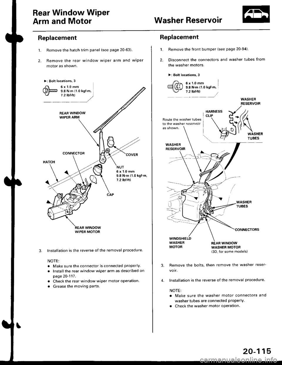
Replacement
't.
2.
Remove the hatch trim panel (see page 20 63).
Remove the rear window wiper arm and wiper
motor as shown.
Installation is the reverse of the removal procedure
NOTE:
. Make sure the connector is connected properly
.Install the rear window wiper arm as described on
page 20-117.
. Check the rear window wiper motor operation.
. Grease the moving parts.
3.
NUT6x1.0mm9.8 N.m 11.0 kgf.m,7.2 tbf.ft)
WIPER MOTOR
L
2.
Replacement
Remove the front bumper (see page 20-94).
Disconnect the connectors and washer tubes from
the washer motors.
>: Bolt locations,3
/)^ 6xt.omm
Ql(S) s.e ru.- tt.o ret '".\./ 7 .2 tbf.ft) /
Route the washer tubes10 the washe. reservoir
wtNDowWASHER MOTOR(3D, for some models)
Remove the bolts, then remove the washer reser-
voir.
Installation is the reverse of the removal procedure.
NOTE:
a Make sure the washer motor connectors and
washer tubes are connected properly.
. Check the washer motor operation.
3.
4.
20-115
Page 1351 of 2189
I t:3D
SECTION AA
012 {0.47) Upper Arm
@20 {0.8) Locat. Hole
Lower Arm Center
Damoer Lower Bush Center
20-121
Page 1362 of 2189
4. Note the position of the ioint on the handle rod (A)'
Prv the handle rod ol the joint using diagonal cut-
ters; take care not to bend the rod Remove the
hatch handle.
BUSHINGReplace.
lnstall in the reverse order of removal, and note
these items:
Make sure
the handle rod is connected properly
Before installing the hatch trim panel, make sure
the hatch opens ProPerlY.
@
Hatch Latch/Lock CYlinder
Replacement
1.
2.
Remove the hatch trim panel (see page 20-63)'
Remove the hatch latch screws
>: Screw locations,3
6x1,0mm9.8 N.m 11.0 kgf'm,
7.2 tbt f0
HATCHLATCH
Disconnect the lock rod, the handle rod, the lock
cylinder rod. and the connector, then remove the
hatch latch.
LOCK CYLINDERROD
''---tCONNECTOR
HANDLEROD
(cont'd)
20-133
Page 1363 of 2189
Opener and Latch
Hatch Latch/Lock Cylinder Replacement (cont'd)
4. Pullthe lock rod out.
lf necessary, remove the lock cylinder.
>: Bolt locelion. 1
6xr.omm I9.8 N.m (1.0 kq .m, I9.8 N.m (1.0 kq .m, I,:!!_J
6. Install in the reverse order of removal, and note
these atems:
. Apply grease to the hatch latch.. Make sure the connector is connected properly.. Before installing the hatch trim panel, make surethe hatch opens properly and locks securely.
ry*)*,,
\""<,/
.z ,/\
20-134
Page 1365 of 2189
DashboardBumpers
I
Center Panel Removal and
Installation
1. Remove the dashboard center lower cover.
2. Remove the screws, then pull out the center panel.
>: Sc.ew locationi,4 >: Clip locationsA >,3B>,4rl
@Y,
UPPER VENT I(NOB
Disconnect the connectors from the heater controlunit and hazard warning switch.
Installation is the reverse of the removal procedure.
NOTE: Make sure the connectors are connectedpropefly.
20-136
Installation is the reverse of the removal procedure.
FRONT BUMPER
a&
Front Grille Removal and
Installation
NOTE: Take care not to scratch the front bumper.
Remove the front bumper. Remove the screws. thenslide the front grille forward by detaching the hooks.
>: Scrow locltion3,6
I
dbp i
Page 1366 of 2189
Front Air SPoiler RePlacement
CAUTION: Put on gloves to protect your hands'
NOTE:
. An assistant is helpful when removing the front bumper'
. Take care not to scratch the front bumper and body'
>: Bolt, screw localions
A >,9 B >,4
s*i@l
BUMPER
lnstallation is the reverse of the removal procedure'
NOTE:
. Make sure the front bumper engages the front
bumper side stiffener on each side securely'
o lf necessary. adjustthe front bumper side stiffener
to obtain the Proper gap.
FRONT AIR SPOILER
20-137
Page 1367 of 2189
Seats
Front Seat Disassembly and Reassembly
CAUTION: When prying with a flat-tip screwdriver, wrap it with protective tape to prevent damage.
NOTE: SEAT-BACK. Take care not to scratch the seat covers and body.. Remove the front seat through the door openlng.
Driver's:
SEAT CUSHION
HEADREST
PIVOT NUTI x 1.25 mm22 N.m 12.2 kgf,m,16 tbf.ft)
CENTER COVER
8 x 1.25 mm
LOWER CAP
RECLINE ADJUSTER
WASHER
20 N.m 12.0 kgf.m,lil lbtftl
WASHERS
EUSHING
10 x 1.25 mm47 N.m (4.8 kgf.m,3s rbl.ft)
INNER SEATTRACKRECLINECOVER
WASHER
8 x 1.25 mm20 N.m (2.0 kg,f.m,14 tbf.fit
LOWER CAPI
8 x 1.25 mm20 N.m {2.0 kgI.rn,l4 tbf.ft)
i\",-,"
20-13A
HEIGHT HANDLE
Page 1368 of 2189
Reassemble in the reverse order of disassembly' and
note these items:
. Make sure the bushing and pivot washer are installed
properly.
. To connect the connecting wire, twist it 90'.
. Replace the back cover clips with new ones
. To prevent wrinkles when installing the seat-back
cover, make sure the material is stretched evenly
over the pad.
. Apply multipurpose grease to the moving portion of
the seat track.
Front Seat Torsion Bar
Replacement
NOTE| Take care not to tear the seams or damage the
seat covers.
1. Remove the seat cushlon
2. Remove the torsion bar from the hook with a flat tip
screwdriver, then pull out the torsion bar from the
seat cushion frame Put on gloves to protect your
ha nds.
TORSIONSAR
SEAT CUSHION FNAME
TORSION BARSEAT CUSHION
FLAT TIP SCREWDRIVER
3. lnstall in the reverse order of removal'
20-139