1999 HONDA CIVIC under dash fuse
[x] Cancel search: under dash fusePage 1677 of 2189
![HONDA CIVIC 1999 6.G Workshop Manual Circuit Diagram (Without Defogger)
UNDER.HOOD FUSE]FELAY BOX
eo;T f-*---;,;r j-_l 6\
OF+-*.v-f r--;. -"j-a,_cy
GN TIONSWITCH
UNDER DASHFUSEIRELAYBOX
BLK]YEL
) I dRGHT LEFTd I dFlGHrf- -- ---\,
HONDA CIVIC 1999 6.G Workshop Manual Circuit Diagram (Without Defogger)
UNDER.HOOD FUSE]FELAY BOX
eo;T f-*---;,;r j-_l 6\
OF+-*.v-f r--;. -"j-a,_cy
GN TIONSWITCH
UNDER DASHFUSEIRELAYBOX
BLK]YEL
) I dRGHT LEFTd I dFlGHrf- -- ---\,](/manual-img/13/6068/w960_6068-1676.png)
Circuit Diagram (Without Defogger)
UNDER.HOOD FUSE]FELAY BOX
eo;T f-*---;',;r j-_l 6\
OF+-*'.v-f r'--;.' -"j-'a,_cy'
GN TIONSWITCH
UNDER DASHFUSEIRELAYBOX
BLK]YEL
) I dRGHT LEFTd I dFlGHr'f- -- ---\,
TT
I
I.t.olo
G551
23-207
(}-
Page 1679 of 2189
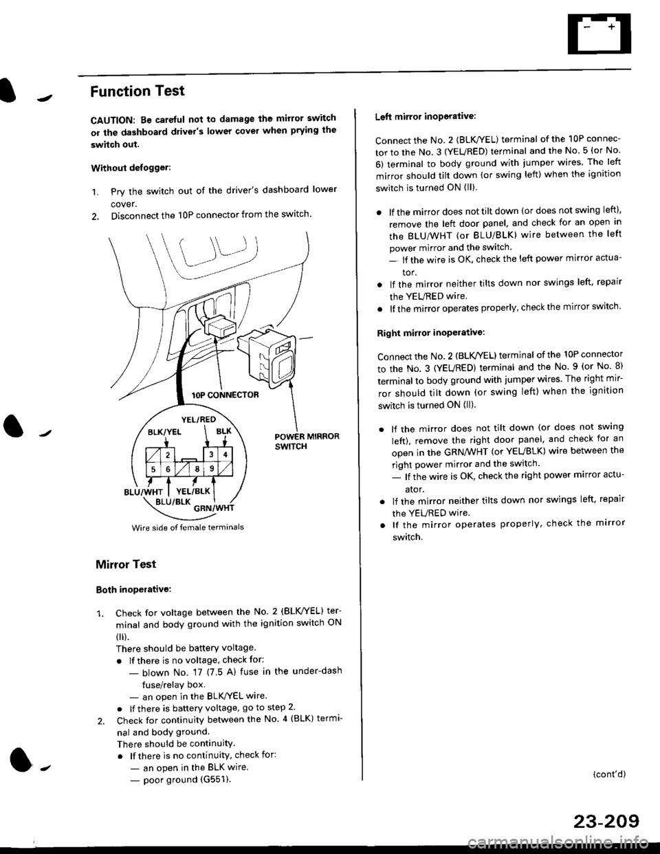
Function Test
CAUTION: Be careful not to damage the mirror switch
or the dashboard drivel's lower covel when prying the
swhch out.
Withoui defogger:
1. Pry the switch out of the driver's dashboard lower
cover.
2. Disconnect the 10P connector from the switch.
lOP CONNECTOR
BLU/WHT
YEL/RED
BLK/YELBLK
4
568
YEL/BLK
POWER MIRRORswtTcH
\:/"*jgil*-(
Wire side of female termanals
Mirror Test
Both inoperative:
1. check for voltage between the No. 2 (BLVYEL) ter
minal and body ground with the ignition switch ON
0 r).
There should be batterY voltage
. If there is no voltage, check for:
- blown No. 17 (7 5 A) fuse in the under-dash
tuse/relay box- an open in the BLK'/YEL wire.
o lf there is battery voltage, go to step 2.
2. Check for continuity between the No 4 (BLK) termi-
nal and body ground.
There should be continuity.
. lf there is no continuity, check for:
- an open in the BLK wire.
- poor ground (G551).
Left mirror inoporalive:
connect the No. 2 {BLK/YEL) terminal of the 10P connec-
tor to the No. 3 (YEURED) terminal and the No 5 (or No
6) terminal to body ground with jumper wires The left
mirror should tilt down (or swing left) when the ignition
switch is turned ON (ll)
. lf the mirror does not tilt down (or does not swing left),
remove the left door panel. and check for an open in
the BLU/WHT (or BLU/BLK) wire between the left
power mirror and the switch
- lf the wire is OK. check the left power mirror actua-
tor.
lf the mirror neither tilts down nor swings left. repair
the YEURED wire.
lf the mirror operates properly, check the mirror switch'
Right mirror inoperative:
Connect the No. 2 (BLK /EL) terminal of the 10P connector
to the No. 3 (YEURED) terminal and the No. 9 (or No 8)
terminal to body ground with jumper wires The right mir-
ror should tilt down (or swing left) when the ignition
switch is turned ON (ll).
. lf the mirror does not tilt down (or does not swlng
left), remove the right door panel. and check for an
open in the GRN/WHT (or YEUBLK) wire between the
right power mirror and the switch.
- lf the wire is OK, check the right power marror actu-
ator.
. lf the mirror neither tilts down nor swings left. repair
the YEURED wire
. lf the mirror operates properly, check the mirror
switch.
(cont'd)
23-209
Page 1680 of 2189
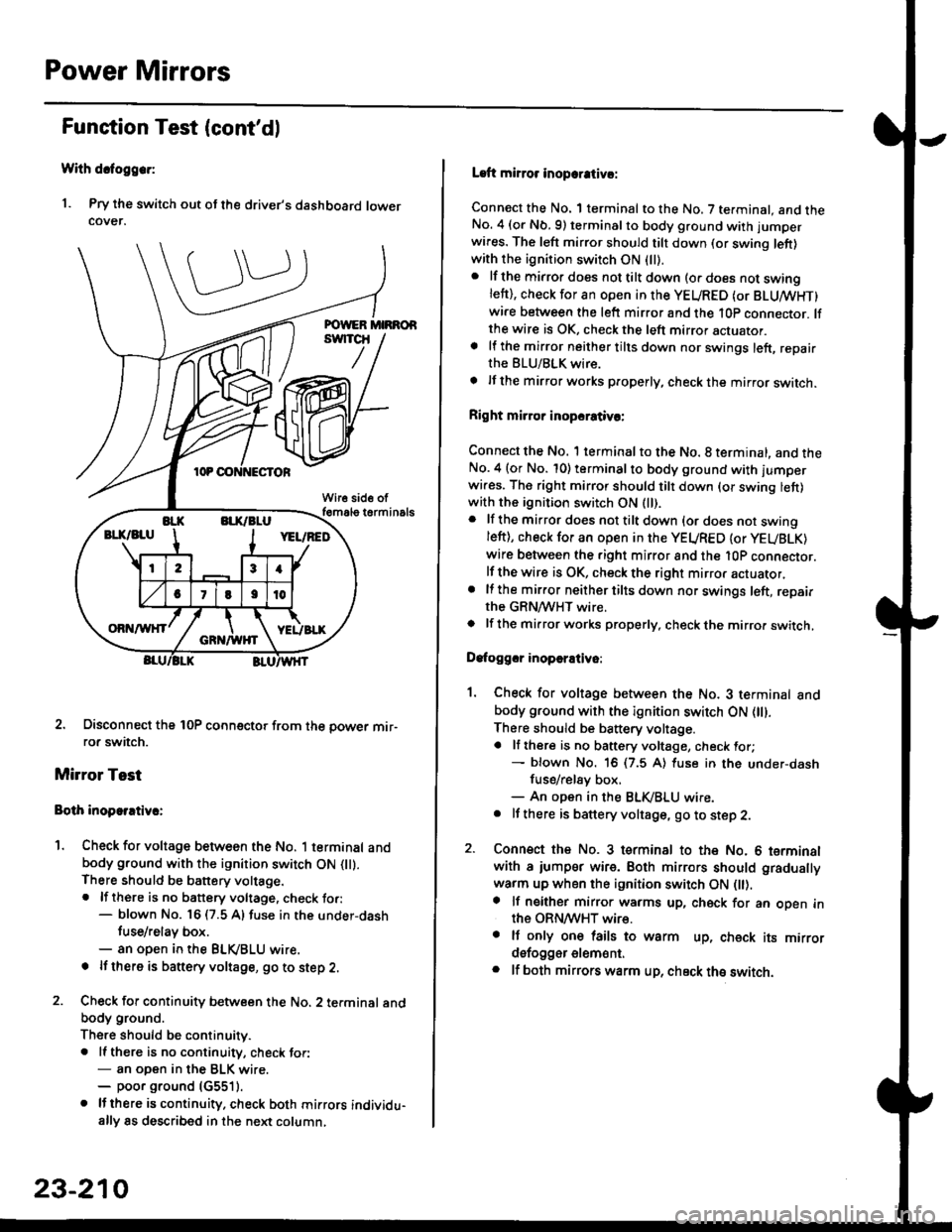
Power Mirrors
Funstion Test (cont'dl
With dcfoggcr:
1. Pry the switch out ot the driver's dashboard lowercover.
2. Disconnect the 10P coonector from the oower mir-ror switch.
Mirror Test
Bolh inoparrtiv.:
1. Check for voltage between the No. 1 terminal andbody ground with the ignition switch ON flt).There should be battery voltage.. lf there is no battery voltage, check to.:- blown No. 16 (7.5 A) fuse in the under-dash
tuse/relay box.- an open in the BLVBLU wrre.
! lf thero is banery voltage, go to step 2.
2. Check for continuity b€tween the No. 2 terminal andbody ground.
There should be continuitv.. ll there is no continuity, check tor:- an open in the BLK wire.- poor ground (G5511.
. lJthere is continuity. check both mirrors individu-ally 8s described in the next column,
23-210
Laft mirror inopcrativ!:
Connect the No. 1 terminal to the No. 7 terminal. and theNo. 4 (or Nb.9) terminalto body ground with jumper
wires. The left mirror should tilt down (or swing left)with the ignition switch ON (ll).
. lf the mirror does not tilt down (o. does not swinglett), check for an open in the YEURED (or BLUMHT)wire between the left mirror and the 10p connector. lfthe wire is OK, check the left mirror actuator.a lf the mirror neither tilts down nor swings left, repairthe BLU/BLK wire.
t lf the mirror works properly, check the mirror switch.
Right mi.ror inopcrativc:
Connect the No. 1 terminal to the No. 8 terminal, and theNo.4 (or No. 10) terminalto body ground with l'umperwi.es. The right mirror should tilt down (or swing lett)with the ignition switch ON (ll).
. lf the mirror does not tilt down {or does not swingleft), check for an open in the YEURED {or YEUBLK)
wire between the right mirror and the l0P connector.lf the wire is OK, check the right mirror actuator,. lf the mirror neither tilts down nor swings left, repairthe GRN/WHT wire.o lf the mirror works properly. check the mirro. switch,
Dafoggcr inoperEtivo:
1. Check for voltage between the No. 3 terminal andbody ground with the ignition switch ON (||).
There should be battery voltage.a lf there is no battery voltage, check for;- blown No. 16 (7.5 A) luse in the under-dash
fuse/rel8y box,- An open in the BLK,iBLU wire.. It there is battery voltage, go to step 2.
2. Connsct the No. 3 tsrminal to the No. 6 terminalwith a iumpsr wire. Both mirrors should gradually
warm up when the ignition switch ON flt).a lf neither mirror warms up, check for an open inthe ORN/WHT wire.. It only on€ lails to warm up, check its mirrordsfogger elem6nt.. lf both mirrors warm up, check ths switch.
Page 1690 of 2189
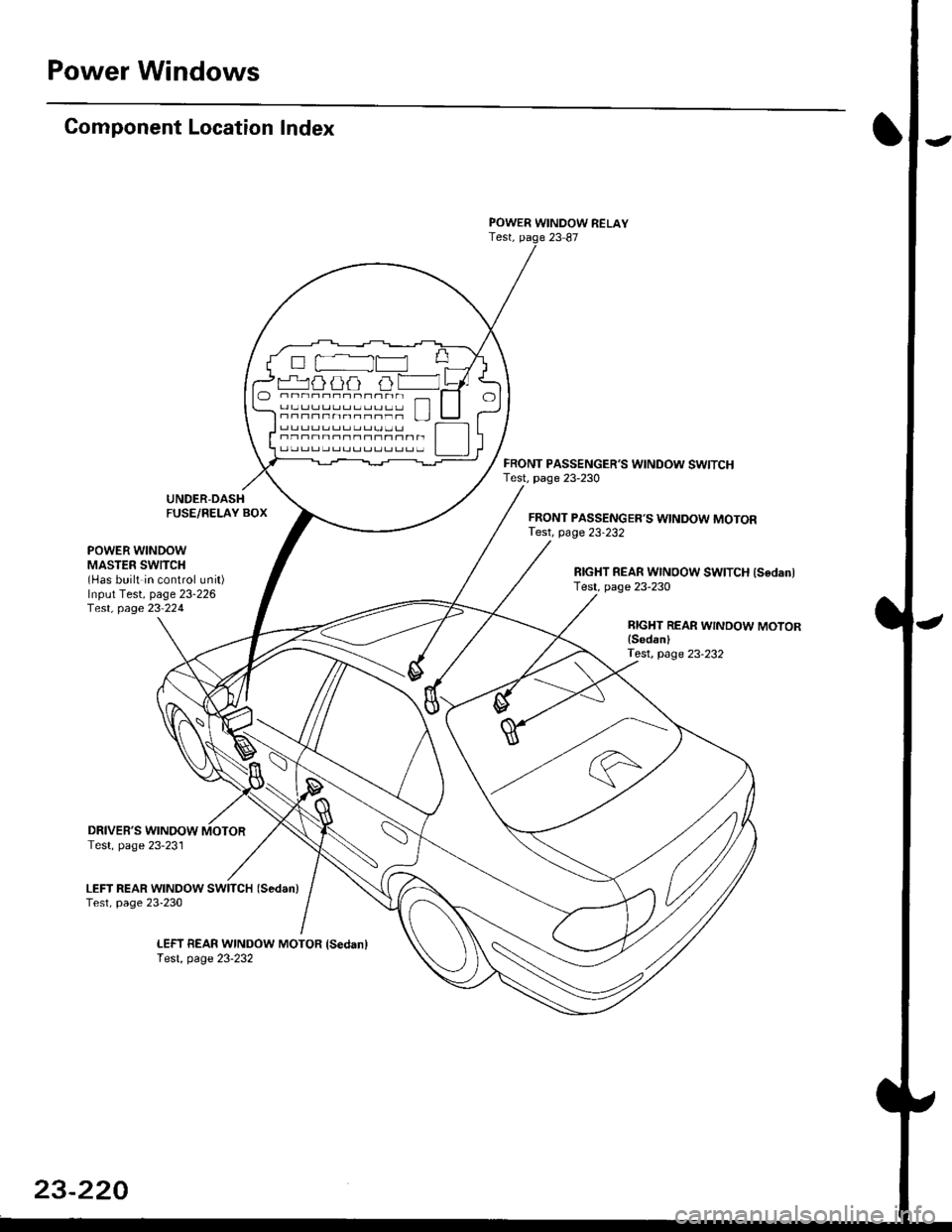
Power Windows
Gomponent Location Index
UNDER-DASHFUSE/RELAY BOX
POWER WINDOW RELAYTest, paqe 23 87
FRONT PASSENGER'S WINDOW SWITCHTest. page 23-230
FRONT PASSENGER'S WINDOW MOTORTest, page 23-232
POWER WINDOWMASTER SWITCH(Has built in control unit)Input Test, page 23-226f e$, page 23 224
RIGHT REAR WINOOW SWITCH {SedanlTest, page 23-230
BIGHT REAR WINDOW MOTORlSedanlTest, page 23-232
DRIVER'S WINOOW MOTORTest, page 23-231
LEFT REAR WINDOW SWITCH (Sedan)
Test, page 23-230
LEFT BEAR WINDOW MOTOR {Sedanlf e$, page 23-232
O -rr----r---- _ fl]l O-.---,---;-; n-n--n-nn--r- ! l
Page 1692 of 2189
![HONDA CIVIC 1999 6.G Workshop Manual Power Windows
Circuit Diagram (96-98 Sedan)
UNDER HOOD FUSE/RELAY BOX
I.iASTER SWITCH
UNDER.DASH FUSUBELAYEOX
BLU/ELK
B3
3 I BIGHT BEAR
l$,]ilP3,y
FBONTPASSENGERSWINDOWswtTcH
BLK
t
G551LEFT HEAF WI HONDA CIVIC 1999 6.G Workshop Manual Power Windows
Circuit Diagram (96-98 Sedan)
UNDER HOOD FUSE/RELAY BOX
I.iASTER SWITCH
UNDER.DASH FUSUBELAYEOX
BLU/ELK
B3
3 I BIGHT BEAR
l$,]ilP3,y
FBONTPASSENGERSWINDOWswtTcH
BLK
t
G551LEFT HEAF WI](/manual-img/13/6068/w960_6068-1691.png)
Power Windows
Circuit Diagram ('96-98 Sedan)
UNDER HOOD FUSE/RELAY BOX
I.iASTER SWITCH
UNDER.DASH FUSUBELAYEOX
BLU/ELK
B3
3 I BIGHT BEAR
l$',]ilP3,y
FBONTPASSENGER'SWINDOWswtTcH
BLK
t
G551LEFT HEAF WINDOWMOTOR
23-222
R GNT REAR WINDOWMOTOR
BLK
I
G551FRONT PASSENGER'SWINOOW MOTOR
c401G402
Page 1699 of 2189
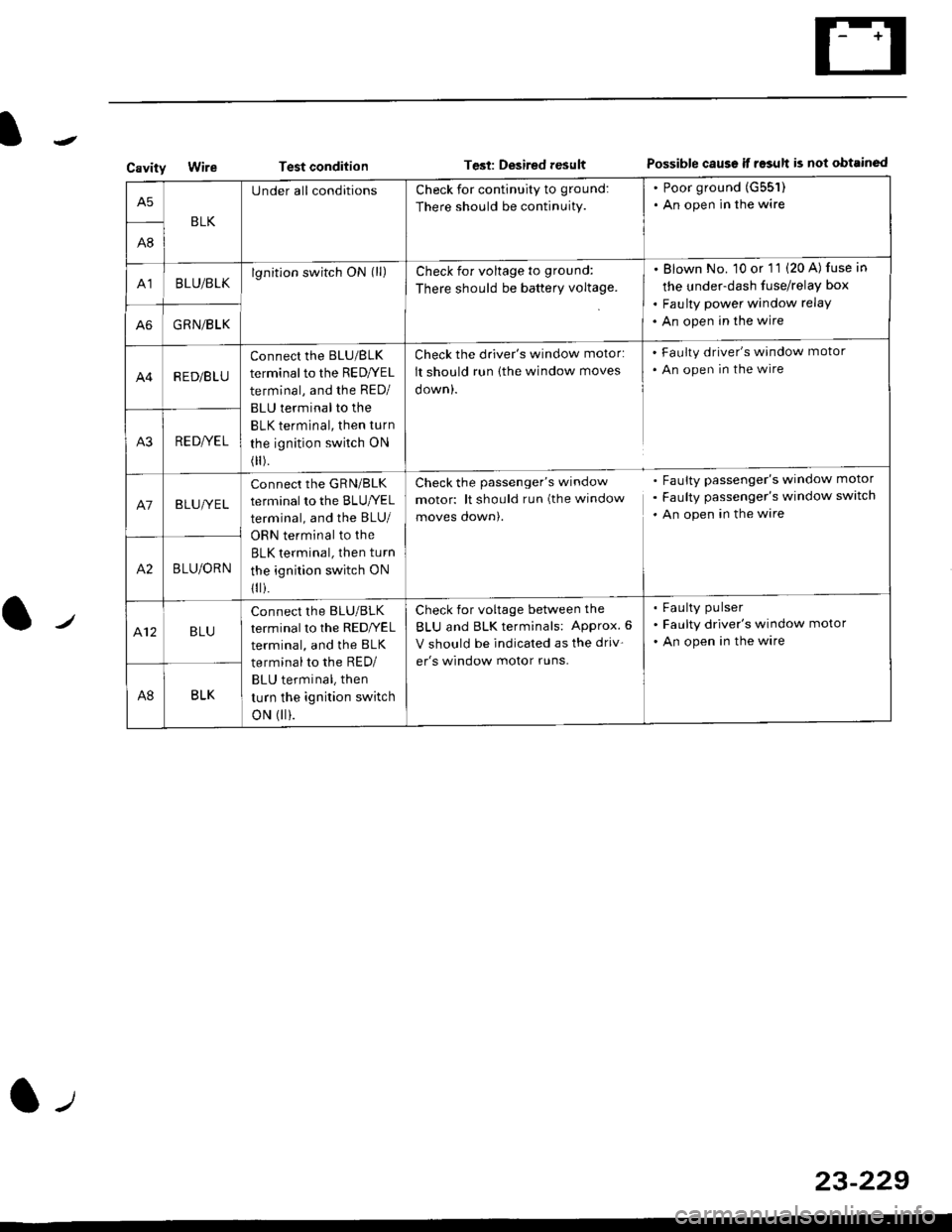
CavityWireTest conditionTest: Desired resultPossible caus€ if result is not obtainsd
BLK
U nderall conditionsCheck for continuity to ground:
There should be continuity.
. Poor ground (G551)
. An open in the wire
A8
A']BLU/BLKlgnitlon switch ON (ll)Check for voltage to ground:
There should be batterY voltage.
Blown No. 10 or '11 (20 A) fuse in
the under-dash fuse/relay box
Faulty power window relay
An open in the wireA6GRN/BLK
R ED/B LU
Connect the BLU/BLK
terminal to the RED/YEL
terminal, and the RED/
BLU terminal to the
BLK terminal, then turn
the ignition swilch ON
(
).
Check the driver's window motor:
It should run (the window moves
oown,.
Check the passenger's window
motor: lt should run (the window
moves qown,.
Check for voltage between the
BLU and BLK terminals: APProx. 6
V should be indicated as the driv-
er's window motor runs.
Faulty driver's window motor
An open in the wire
Faulty passenger's window motor
Faulty passenger's window switch
An open in the ware
Faulty pulser
FaLilty driver's window motor
An open in the wire
A3RE D/YE L
A7BLUI/E L
connect the GRN/BLK
terminal to the BLUryEL
terminal, and the BLU/
ORN terminal to the
BLK terminal, then turn
the ignition switch ON
1
i.
A2BLU/ORN
412BLU
Connect the BLU/BLK
terminal to the REDI/EL
terminal, and the BLK
terminal to the RED/
BLU terminal, then
turn the ignition switch
oN (|| ).
A8BLK
23-229
Page 1707 of 2189
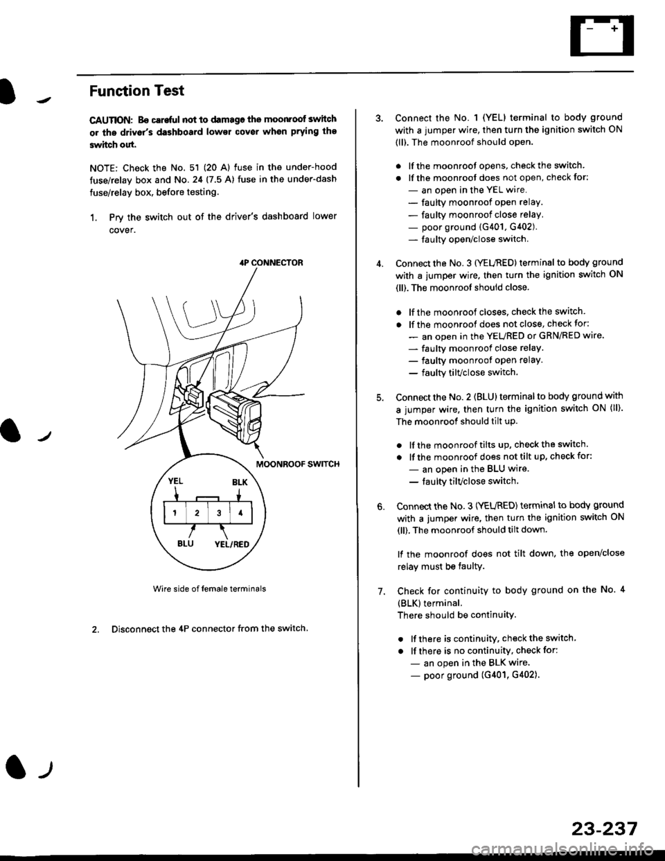
Funstion Test
CAUTION: Bo careful not to damago the moonroof switch
or ths driv6r's dashboard lowsr cover when prying the
3witch out.
NOTE: Check the No. 51 (20 Al fuse in the under-hood
tuse/relay box and No.24 (7.5 A) fuse in the under-dash
fuse/relay box, before testing.
1. Prv the switch out of the driver's dashboard lower
cover.
swtTcH
Wire side of female terminals
2. Disconnect the 4P connector from the switch
4P CONNECTOR
l-t
23-237
Connect the No. 1 (YELI terminal to body ground
with a jumper wire, then turn the ignition switch ON
(ll). The moonroof should open.
. lf the moonroot opens, check the switch.
. lf the moonroot does not open, check for:
- an open in the YEL wire.
- faulty moonroof open relay.
- faulty moonroof close relay,
- poor ground (G401, G402).- fa u lty open/close switch.
Connect the No. 3 (YELnED) terminal to body ground
with a jumper wire. then turn the ignition switch ON
(ll). The moonroof should close.
. lf the moonroof closes. check the switch.
. lf the moonrool does not close, check for:
- an open in the YEURED or GRN/RED wire'
- faulty moonroof close relaY.
- faulty moonroot oPen relaY.
- faulty tilvclose switch.
Connect the No. 2 (BLU) terminal to body ground with
a jumper wire, then turn the ignition switch oN (ll).
The moonroof should tilt up.
. lf the moonroof tilts up, checkthe switch.
. lf the moonroof does nottilt up, checkfor:
- an open in the BLU wire.
- taulty tilvclose switch
Connect the No. 3 (YEURED) terminal to bodY ground
with a jumper wire, then turn the ignition switch ON
(ll), The moonroof should tilt down.
lf the moonroof does not tilt down, the open/close
relay must be taulty.
Check for continuity to body ground on the No. 4
{BLK}terminal.
There should be continuity.
. lf there is continuity, check the switch
. lf there is no continuity, check for:
- an open in the BLK wire
- poor ground (G401, G402).
6.
7.
Page 1713 of 2189
)
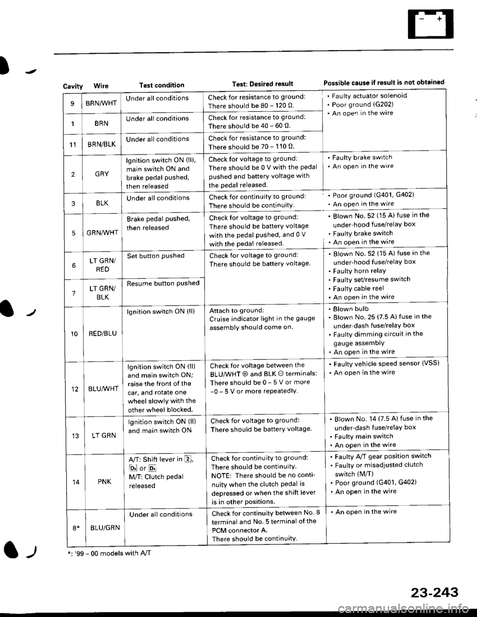
CavityWireTest conditionTest: Desired resultPossible cause if result is not obtained
BRNA/VHTUnder all conditionsCheck for resistance to ground:
There should be 80 - 120 O.
Fau lty actuator solenoid
Poor ground (G202)
An open in the wire
1BRNUnder all conditionsCheck for resistance to ground:
There should be 40 - 60 0.
11BRN/BLKUnder all conditionsCheck for resistance to ground:
There should be 70 - 110 0.
2GRY
lgn jtion switch ON (ll),
main switch ON and
brake pedal pushed,
then released
Check for voltage to ground:
There should be 0 V with the Pedal
pushed and battery voltage with
the pedal released.
'Faulty brake switch
. An open In the wlre
3BLKU nderall conditionsCheck for continuitY to groundl
There should be continuity
' Poor ground (G401, G402)
. An open in the wire
5GRNA,A/HT
Brake pedal pushed,
then released
Check for voltage to groundl
There should be batterY voltage
with the Pedal Pushed. and 0 V
with the pedal released
. Blown No. 52 (15 A) fuse in the
under-hood fuse/relaY box
. Faulty brake switch. An open in the wire
LT GRN/
RED
Set button pushedCheck for voltage to ground:
There should be batterY voltage.
Blown No. 52 (15 A) fuse in the
under-hood fuse/relaY box
Faulty horn relay
Faulty sevresume switch
Faulty cable reel
An open in the wire7LT GRN/
BLK
Resume button Pushed
10RED/BLU
lgnition switch ON (ll)Attach to ground:
Cruise indicator light in the gauge
assembly should come on.
Blown bulb
Blown No. 25 (7.5 A) fuse in the
under dash fuse/relay box
Faulty dimming circuit in the
gauge assemDly
An open in the wire
BLU,A/VHT
lgnition switch ON (ll)
and main swilch ON;
raise the front of the
car, and rotate one
wheel slowly with the
other wheel blocked.
Check for voltage between the
BLUMHT @ and BLK O terminals:
There should be 0- 5 V or more
-0- 5 V or more repeatedlY
. Faulty vehicle speed sensor {VSS)
. An open in the wire
LT GRN
lgnition switch ON (ll)
and main switch ON
Check for voltage to ground:
There should be batterY voltage.
Blown No. 14 (7.5 A)fuse in the
under-dash luse/relaY box
Faulty main switch
An open in the wire
14PNK
A,T: Shift lever in E,
ojorE
M/T: Clutch pedal
released
Check for continuity to ground:
There should be continuity.
NOTE: There should be no conti-
nuity when the clutch Pedal is
depressed or when the shift lever
is in other positions.
Faulty A/f gear position switch
Faulty or misadjusted clutch
switch (M/T)
Poor ground (G401, G402)
An open in the wire
BLU/GRN
Under all conditionsCheck for continuity between No. I
terminal and No. 5 terminal of the
PCM connector A.
There should be continuity
. An open in the wire
*: '99 - 00 models with A,/Tl-,
23-243