1999 HONDA CIVIC dash board
[x] Cancel search: dash boardPage 2123 of 2189
Connector Views (cont'd)
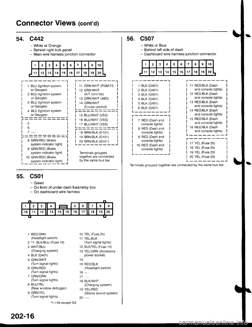
54. c442
- White or Orange- Behind right kick panel- l\,lain wire harness junction connector
r---------Tr---------"1
1 BLU (lgnition systemor Gauges)
2 BLU (lgnition syslemor Gauges)
3 BLU (lgnition systemor Gauges)
4 BLU (lgnition system
L_ or causes)L_-:-:::'-'�____Jt-----------1
11 GRN/WHT (PGM-FD
12 GRN/WHT(A/T controls)
13 GRNMHT (ABS)
14 GRNMHT
L_ lc,r'." .oIr"D_ _ _.jr----------_l
5
6
7L---------JT----------l8 GRN/RED (Brake
system indicator light)
9 GRN/RED (Brake
system indicator light)
10 GRN/RED (Brake
_ system indicator ligh0 -..1
| 15 BLUMHT (vSS) |I 16 BLUMHT (VSS) I
L T?_BLUSTrySS)--..]
l--------- - -l
| 18 BFN/BLK (G101) I| 19 BBN/BLK (G101) || 20 BRN/BLK (c101) |L---------J
Terminals groupedtogether are connectedby the same bus bar.
55. C501
- Green- On tront of under-dash tuse/relay box- On dashboard wire harness
l RED/GFN(Headlight switch)
2 *1 : BLKBLU (Fuse 16)
3 WHT/BLU(Charging systern)
4 BLK (G401)
5 GRNMHT(Turn signal lights)
6 GRN/RED(Turn signal lights)
7 GRN/ORN(Turn signal lights)
8 8LU/YEL(Rear w ndow delogger)
9 GFN/YEL(Turn signal lights)
'10 YEL (Fuse 25)
11 YEL/BLK(Turn signal lights)
12 BLKTYEL (Fuse 14)
13 YEUGRN (Accessorypower socket)
15 RED/BLK(Headlight switch)
1B BLK/WHT(Charglng system)
19 YEL/RED(Stereo sound system)
20
202-16
-1 =All e),cept GX
s6. c507
- White or Blue- Behind left side oJ dash- Dashboard wire harness junction connector
r --------'lT---------l
7 BED (Dash andconsole lights)
B BED (Dash andconsole lights)
I RED (Dash andconsole lights)
10 RFD (Dash andconsole lights)
11 RED/BLK (Dash
and console lights)
12 RED/8LK (Dash
and console lights)
13 RED/BLK {Dashand console lights)
14 RED/BLK (Dash
and console lights)
15 RED/BLK (Dash
and console lights)
16 RED/BLK (Dash
and console lights)L--------J
T--------T
L---_---_J
1 BLK (G401)
2 BLK (G401)
3 8LK {G401)4 8LK (G401)
5 BLK (G401)
6 8LK (G401)L________J
T--------"1
17 YEL (Fuse 25)
18 YEL (Fuse 25)
19 YEL (Fuse 25)
20 YEL (Fuse 25)L--------J
Term nals grouped together are connected by the same bus bat
Page 2127 of 2189
Connector Views (cont'd)
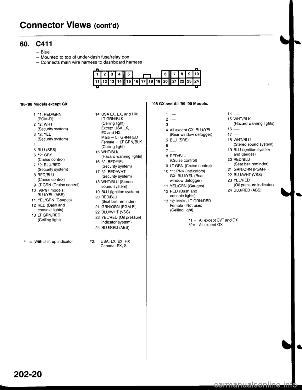
60. c411
- Blue- Mounted to top ol under-dash fuse/relay box- Connects main wire harness to dashboard harness
'95198 Models excepl GXI
1 *1: RED/GRN(PGrvr-FD
2 A2: WHT(Security system)
(Security system)
4
5 BLU (SRS)
6 *2r GRY(Cruise control)
7 *2: BLU/RED(Security system)
8 RED/BLU(Cruise control)
9 LT GRN (Cruise control)
10 '96-�97 models:BLU/YEL (ABS)
11 YEUGRN (Gauges)
12 RED (Dash andconsole lights)'13 LT GRN/RED(Ceiling light)
*1 = With shitt-up indicator
14 USA LX, EX, and HX:LT GRN/BLK
{Ceiling light)Except USA LX,EX and HX:ftrale - LT GRN/REDFemale - LT GRN/BLK(Ceiling light)
15 WHT/BLK(Hazard warning lights)
16 *2: RED|YEL(Security system)
17 *2: REDA/VHT(Security system)
18 WHT/BLU (Stereo
sound system)
19 BLU (lgnition system)
20 RED/BLU(Seat bett reminder)
21 GRN/OBN (PGN4 FD
22 BLUAVHT (VSS)
23 YEURED (Oil pressure
indicator system)
24 BLU/RED (ABS)
USA: LX: EX, HXCanadar EX, Si
202-20
'98 GX and All '99-'00 Models:
1
2
4 All except GX: BLU/YEL(Rear window defogger)
5 BLU (SRS)
7
B RED/BLU(Cruise control)
9 LT GRN {Cruise control)
10 *1: PNK (lnd cators)GX: BLU/YEL (Bear
window defo9ger)
1l YEL/GBN (Gauges)
12 RED (Dash andconsole lights)
13 *2: Male - LT GRN/REDFemale - Not used(Ceiling light)
14
15 WHT/BLK(Hazard warning lights)
18 WHT/BLU(Stereo sound system)
19 BLU (lgnition systemano gaugesl
20 RED/BLU(Seat bell reminder)
21 GRN/ORN (PG[,4-Fl)
22 BLU,ryVHT O/SS)23 YEURED(Oil pressure indicator)
24 BLU/RED (ABS)
*1 = Allexcept CW and GX*2= All except GX
Page 2131 of 2189
Gonnector Views (cont'd)
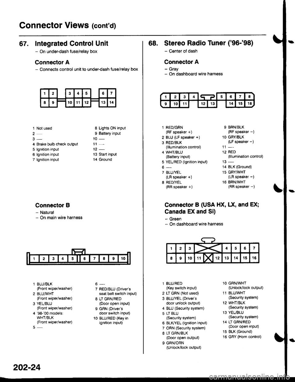
67. Integrated Control Unit
- On underdash fuse/relay box
Connector A
- Connects control unit to under-dash fuse/relay box
1 Not used
4 Erake bulb check output
5 lgnition input
6 lgnition input
7 lgnjtion input
Connectol B
- Natural- On main wire harness
l BLU/BLK
{Front wiper/washer)
2 BLUA/VHT(Front wiper/washe0
3 YEUBLU(Front wiper/washer)
4 '98-'00 models:WHT/BLK(Front wiper/washer)
8 Lights ON input
9 Battery input
11 _
13 Start input
14 Ground
7 RED/BLU (Driver's
seat b€lt switch input)
8 LT GRN/RED(Door open input)
I GRN (Oriver's
door switch input)'t0 BLU/RED (Key inignition input)
202-24
68. Stereo Radio Tuner ('96-'98)
- Center ot dash
Connector A
- Gray- On dashboard wire harness
1 RED/GRN(RF speaker +)
2 BLU (LF speaker +)
3 RED/BLK(lllumination control)
4 WHT/BLU(Battery input)
5 YEURED (lgnition input)
6-
7 BLU/YEL(LR speaker +)
8 RED/TEL(RR speaker +)
9 BRN/BLK(RF speaker -)
1O GRY/BLK(LF speaker -)
12 RED(lllumination control)
14 BLK (Ground)
15 GFY,4/VHT(LR speaker -)
16 BRNAVHT(RR speaker -)
Connector B (USA HX, UX, and EX;
Canada EX and Si)
- Green- On dashboard wire harness
l BLU/RED(Key switch input)
2 LT GRN (Not used)
3 BLU/'EL (Drivels
door unlock output)
4 BLU (Security system)
5 LT BLU
{Security system)
6 BLIVYEL (lgnition input)
7 ORN (Security system)
8 LT GRN/BLK(Door open output)
9 GRN/ORN(Unlock/lock output)
1O GRNAVHT(Unlock/lock output)
1 1 BLU/WHT(Security system)
'2 WHT/BLK(Security system)
13 YEUBLU(Security system)
14 LT GRN/RED(Door open input)
15 BLK (Ground)
16 GRY (Horn conkol)
Page 2137 of 2189
Connector Views (conrd)
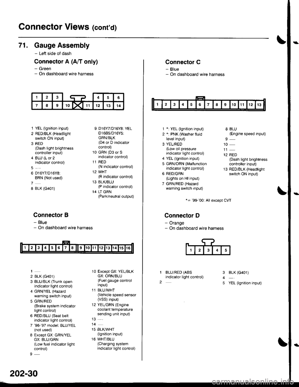
71. Gauge Assembly
- Left side of dash
Connector A (A/T only)
- Green- On dashboard wire harness
1 YEL (lgnition input)
2 RED/BLK (Headlight
switch ON input)
3 RED(Dash light brightnesscontroller input)
4 BLU (L or 2indicator control)
6 D16Y7/D16Y8:BRN (Not used)
8 BLK (G401)
Connector B
- Blue- On dashboard wire harness
2 BLK (G401)
3 BLU/BLK (Trunk openindicator light control)
4 GRN/YEL (Hazard
warning switch input)
5 GRN/RED(Brake system indicatorlight control)
6 RED/BLU (Seat beltindicator light control)
7 '96-'97 model: BLU,ryEL(not used)
8 Except GX: GRN/YELGX: 8LU/GRN(Low fuel indicator lightcontrol)
9 D16Y7/D16Y8: YEL01685/016Y5:GRN/BLK(D4 or D indicatorcontrol)
10 GRN (03 or Sindicator control)
11 RED(N indicator control)
12 WHT(F indicator control)
13 BLI(BLU(P indicator control)
14 LT GBN(Park/neutral output)
10 Except GX: YEUBLKcX: ORN/BLU(Fuel gauge controlinput)
11 BLUAVHT(Vehicle speed sensor(VSS) input)
12 YEUGRN (Engine
coolant temperaturesending unit input)
14
15 BLI(IVHT(lgnition input)
16 WHT/BLU(Charging systemindicator light control)
202-30
Connector C
- Blue- On dashboard wire harness
1 *: YEL (lgnition input)
2 *: PNK (Washer lluidlevel input)
3 YEUBED(Low oil pressureindicator light control)
4 YEL (lgnition input)
5 GRN/ORN (Malfunctionindicator light control)
6 RED/GRN
{Lights on Hl input)
7 GBN/RED (Hazardwarning switch input)
*= '99-'00: All except CVT
Connector D
- Orange- On dashboard wire harness
BLU/RED (ABS
indicator light control)
8 BLU(Engine speed input)
10
12 FED(Dash light brightnesscontroller input)
13 RED/BLK (Headlightswitch ON input)
I
2
3
4
5
BLK (G401)
YEL (lgnition input)
Page 2138 of 2189
\
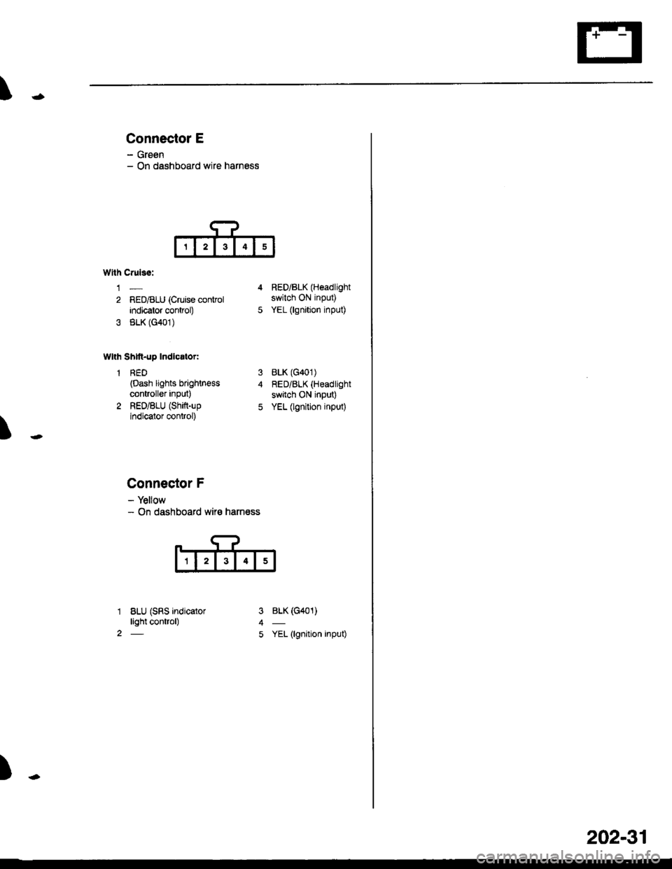
Connector E
- Groen- On dashboard wire harness
T
Wllh Crulss:
1-
2 RED/BLU (Cruise conkolindicator control)
3 BLK (G401)
Wlth Shtft-up Indlcator:
1 RED(Dash lights brightn€ss
controller inPut)
2 RED/BLU (Shift-up
indicator control)
4 RED/BLK (Headlight
switch ON input)
5 YEL (lgnition input)
BLK (G401)
RED/BLK (Headlight
switch ON input)
YEL (lgnition input)
BLK (G401)
YEL (lgnition input)
3
5
1
2
Connector F
- Yellow- On dashboard wir€ harness
BLU (SRS indicatorlight control)
)-
202-31
Page 2161 of 2189
Connector ldentification and Wire Harness Routing
Connector
or
Terminal
Number ol
Cavities/
Color
LocationConnects toNotes
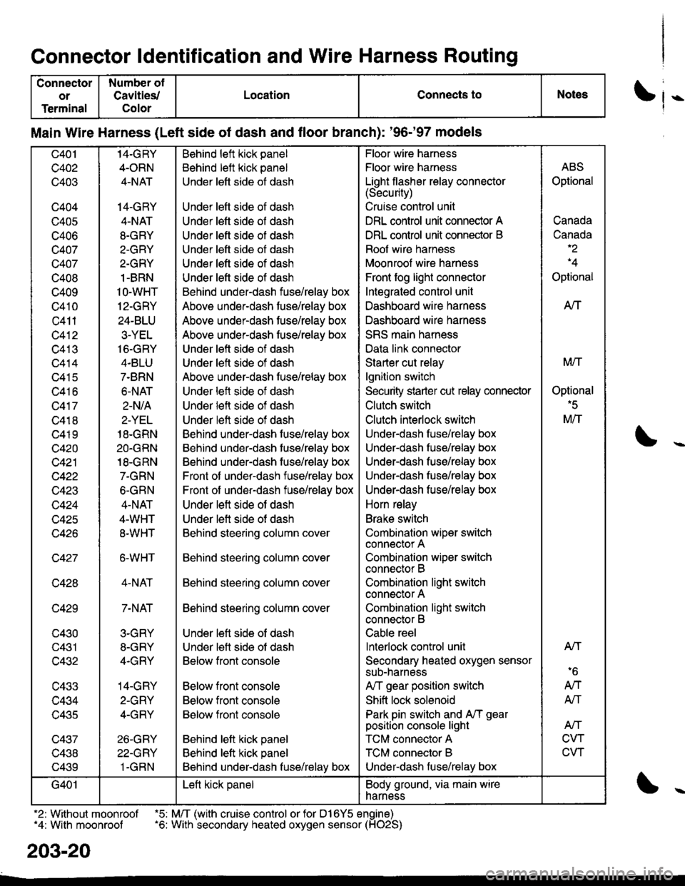
Main Wire Harness (Left side of dash and floor branch): '96-'97 models
c401
c402
c403
c404
c405
c406
c407
c407
c408
c409
c410
c411
c412
c413
c414
c415
c416
c417
c418
c419
c420
c421
c422
w+4J
c424
c425
c427
c428
c429
c430
c431
c432
c433
c434
lJ+OC
c437
v+.to
c439
14-GRY
4-ORN
4-NAT
14-GRY
4-NAT
8-GRY
2-GRY
2-GRY
1-BRN
1O-WHT
12-GRY
24-BLU
3-YEL
16-GRY
4.BLU
7-BRN
6.NAT
2-N/A
2-YEL
18-GRN
2O.GRN
18-GRN
7-GRN
6-GRN
4-NAT
4-WHT
8.WHT
6-WHT
4-NAT
7-NAT
3-GRY
8-GRY
4.GRY
14-GRY
2-GRY
4-GRY
26-GRY
22-GRY
1-GRN
Behind left kick panel
Behind left kick panel
Under left side ot dash
Under left side of dash
Under left side of dash
Under left side of dash
Under lett side ot dash
Under left side of dash
Under left side of dash
Behind under-dash fuse/relay box
Above under-dash fuse/relay box
Above under-dash fuse/relay box
Above under-dash fuse/relay box
Under left side of dash
Under left side of dash
Above under-dash fuse/relay box
Under left side of dash
Under left side of dash
Under left side of dash
Behind under-dash fuse/relay box
Behind under-dash fuse/relay box
Behind under-dash fuse/relay box
Front of under-dash iuse/relay box
Front of under-dash fuse/relay box
Under left side of dash
Under left side of dash
Behind steering column cover
Behind steering column cover
Behind steering column cover
Behind steering column cover
Under left side of dash
Under lett side ot dash
Below front console
Below front console
Below front console
Below front console
Behind lett kick panel
Behind left kick panel
Behind under-dash fuse/relay box
Floor wire harness
Floor wire harness
Light flasher relay connector(Security)
Cruise control unit
DRL control unit connector A
DRL control unit connector B
Roof wire harness
Moonroof wire harness
Front fog light connector
Integrated control unit
Dashboard wire harness
Dashboard wire harness
SRS main harness
Data link connector
Starter cut relay
lgnition switch
Security starter cut relay conneclor
Clutch switch
Clutch interlock switch
Under-dash fuse/relay box
Underdash fuse/relay box
Under-dash fuse/relay box
Under-dash fuse/relay box
Underdash fuse/relay box
Horn relay
Brake switch
Combination wiper switch
connector A
Combination wiper switch
connector B
Combination light swilch
connector A
Combination light switch
connector B
Cable reel
lnterlock control unit
Secondary heated oxygen sensor
sub-narness
A,/T gear position switch
Shift lock solenoid
Park pin switch and A,/T gear
position console light
TCM connector A
TCM connector B
Under-dash luse/relay box
ABS
Optional
Canada
Canada-2
'4
Optional
AtT
M/T
Optional'5
M/T
Atl
'6
AN
AN
Atf
CVT
CVT
G401Left kick panelBody ground, via main wire
harness
.2: Without moonroof .5: M/T (with cruise control or for D16Y5 engine)"4: With moonroof .6: With secondary heated oxygen sensor (HO2S)
203-20
Page 2163 of 2189
Connector ldentification and Wire Harness Routing
Connector
or
Terminal
Number of
Cavities/
Color
LocationConnects toNotess
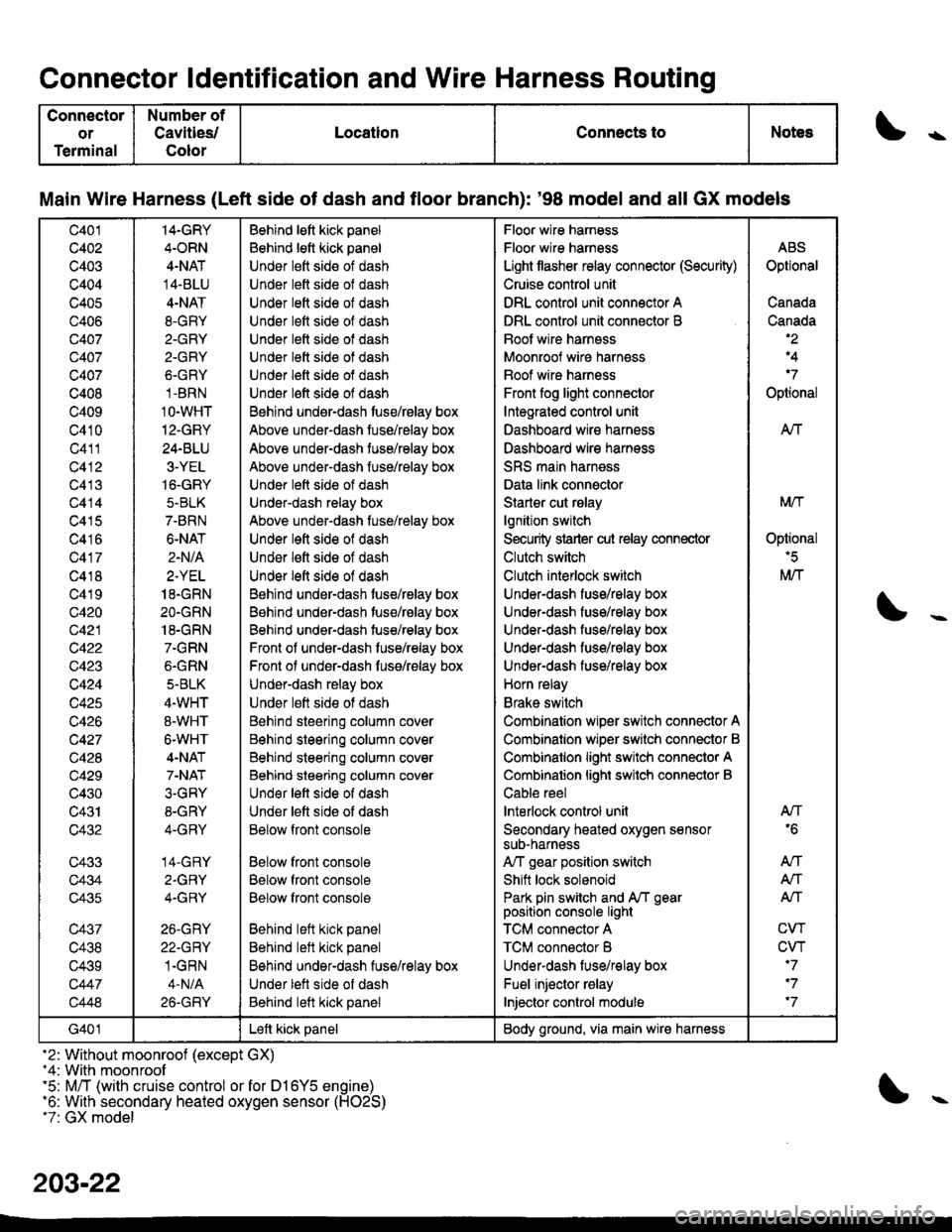
Main Wire Harness (Left side of dash and tloor branch): '98 model and all GX models
c401
c402
c403
c404
c405
c406
Q407
c407
c407
c408
c409
c410
c411
c412
c413
c414
c415
c416
c417
c418
c419
c420
c421
c422
c423
c424
c425
c426
c427
c428
c429
c430
c431
c432
c433
c434
c435
c437
c438
c439
c447
c448
14-GRY
4.ORN
4-NAT
14-BLU
4-NAT
8.GRY
2.GRY
2-GRY
6.GRY
1-BRN
1O-WHT
12-GRY
24-BLU
3-YEL
16-GRY
5-BLK
7-BRN
6-NAT
2.N/A
2.YEL
18.GRN
2O.GRN
18-GRN
7.GRN
6.GRN
5-BLK
4.WHT
8-WHT
6-WHT
4-NAT
7-NAT
3.GRY
8-GRY
4-GRY
14-GRY
2.GRY
4.GRY
26.GRY
22-GRY
1.GRN
4-N/A
26-GRY
Behind lett kick panel
Behind lett kick panel
Under lett side of dash
Under lett side ol dash
Under lett side of dash
Under left side of dash
Under lett side of dash
Under lett side ot dash
Under left side of dash
Under l€ft side of dash
Behind undsr-dash tuse/rBlay box
Above under-dash tuse/relay box
Above under-dash tuse/relay box
Above under-dash fuse/relay box
Under lett side of dash
Under-dash relay box
Above under-dash tuse/relay box
Under left side of dash
Under lett side of dash
Under left side of dash
Behind under-dash tuse/relay box
Behind under-dash tuse/relay box
Behind under-dash tuse/relay box
Front of under-dash tuse/relay box
Front ol under-dash fuss/relay box
Under-dash relay box
Under lett side ot dash
Behind steering column cover
Behind steering column cover
Behind steering column cover
Behind steering column cover
Und€r left side of dash
Under lett side of dash
Below front console
Below front console
Below front console
Below front console
Behind left kick panel
Behind left kick panel
Behind under-dash fuse/relay box
Under lett side of dash
Behind left kick panel
Floor wire harness
Floor wire harness
Light tlasher relay connector (Security)
Cruise control unit
DRL control unit connector A
DRL control unit connector B
Boot wire harnsss
Moonroof wire harness
Boof wire harness
Front fog light connector
Integrated control unit
Dashboard wire harness
Dashboard wire harness
SRS main harness
Data link connector
Starler cut rslay
lgnition switch
Security strarter cut relay connector
Clutch switch
Clutch interlock switch
Under-dash fuse/relay box
Under-dash fuse/relay box
Under-dash fuso/rolay box
UndeFdash fuse/relay box
Under-dash fuse/relay box
Horn relay
Brake switch
Combination wiper switch connector A
Combinalion wiper srvitch connector B
Combinalion light switch connector A
Combinalion lighi swilch connector B
Cable reel
lnterlock control unil
Secondary heated oxygen sensorsuD-narness
A,/T gear position switch
Shift lock solenoid
Park pin switch and A/T gearposition console light
TCM connector A
TCM connector B
Underdash lus€/relay box
Fuel injector relay
Injector control module
ABS
Optional
Canada
Canada,2
,4
'7
Optional
AIf
Mtf
Oplional'5
M/T
AN'6
An
A,/T
Alf
CW
CVT'7
'7
'7
G401Left kick panelBody ground, via main wire harness
-2: Without moonroof (except GX)-4: With moonroof'5: M/T (with cruise control or for D16Y5 engine)'6: With secondary heated oxygen sensor (H02S)t7: GX model
203-22
Page 2165 of 2189
Connector ldentification and Wire Harness Routing
Connector
ol
Terminal
Number ot
Cavlties/
Color
LocationConnects toNotes\
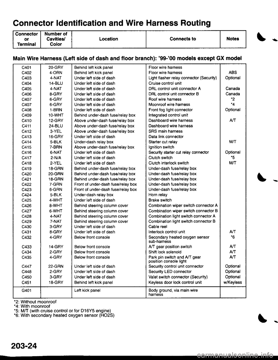
Main Wire Harness (Left side of dash and floor branch): '9$00 models except GX model
c401
c402
c403
c404
c405
c406
c407
c407
c408
c409
c4t0
Q411
c412
c413
c414
c415
c416
c417
c418
c419
c420
c42'l
c423
c424
c425
c426
c42A
c429
c430
c431
c432
c433
c434
c435
c447
c448
c450
c451
2O.GRY
4.ORN
4.NAT
14.BLU
4-NAT
8-GRY
6.GRY
6.GRY
1-BRN
1o-wHT
12-GRY
24-BLU
3.YEL
16-GRY
5.BLK
7-BRN
6.NAT
2-N/A
2-YEL
18.GRN
2O.GRN
18.GRN
7.GRN
6.GRN
5-BLK
4.WHT
8.WHT
6-WHT
4-NAT
7.NAT
3.GRY
8.GRY
4-GRY
14-GRY
2-GFY
4-GRY
22.GRN
2-GRY
3-GRY
18-GRY
Behind left kick panel
Behind left kick panel
Under left side of dash
Under lett side oI dash
Under lett side of dash
Under letl side ol dash
Under lett side oI dash
Under letl side oI dash
Under lefl sids ol dash
Behind under-dash fuse/relay box
Above under-dash fuse/relay box
Above under-dash fuse/relay box
Above under-dash fuse/relay box
Under lett side ot dash
Under-dash relay box
Above under-dash fuse/relay box
Under left side of dash
Under left side ot dash
Under lett side of dash
Behind under-dash fuse/relay box
Behind under-dash fuss/relay box
Behind under-dash fuse/relay box
Front of under-dash fuse/relay box
Front of under-dash fuse/relay box
Under-dash relay box
Under loft side ot dash
Bohind steering column cov6r
B6hind stesring column cover
Behind steering column cover
Behind steering column cover
Under lett side ot dash
Under lett side ot dash
Below fronl console
Below front console
Below front console
Below front console
Under lett side ot dash
Under lett side of dash
Under left side of dash
Behind lett kick panel
Floor wire harness
Floor wire harness
Light flasher relay connector (Sscurity)
Cruise control unil
DRL control unit connector A
DRL control unit conn€ctor B
Roof wire harness
Moonroof wire harnsss
Front tog light connector
Intsgratgd control unit
Dashboard wire harn€ss
Dashboard wire harness
SRS main harness
Data link connector
Starter cut relay
lgnition switch
S€curity starter cut relay connector
Clutch switch
Clulch interlock switch
Under-dash fuse/relay box
Under-dash tuse/ralay box
Under-dash tuse/ralay box
Under-dash fuse/relay box
Under-dash fuse/relay box
Horn relay
Brake switch
Combination wiper switch connector A
Combination wiper switch conn€ctor B
Combination light switch connector A
Combination light switch conn€ctor B
Cable reel
lnterlock control unit
Secondary heated oxygen sensorsub-narnsss
A/T gsar position switch
Shitt lock solenoid
Park pin switch and A/T gearposition consolo light
Security control unit connactor
Security LED connector
Valet switch connector (Security)
Keyless door lock control unit
ABS
Optional
Canada
Canada
Optional
AN
Mrl
Optional'5
M/T
AN'6
An
Atf
Atf
Optional
Optional
Optional
MKoyloss
G401Left kick panelBody ground, via main wirenarness
'2: Without moonroof"4: With moonroof'5: M/T (with cruise control or for D16Y5 engine)'6: With secondary heated oxygen sensor (HO2S)
203-24