Page 1399 of 2189
![HONDA CIVIC 1999 6.G Workshop Manual Mode control motor does not run.
or one or more modes arc inope]a-
tive.
Check the No. 17 (7.5 A) fuse in
the under-dash fuse/relay box.
Replace the Iuse. and recheck.
Check for an open in the wire:
1 HONDA CIVIC 1999 6.G Workshop Manual Mode control motor does not run.
or one or more modes arc inope]a-
tive.
Check the No. 17 (7.5 A) fuse in
the under-dash fuse/relay box.
Replace the Iuse. and recheck.
Check for an open in the wire:
1](/manual-img/13/6068/w960_6068-1398.png)
Mode control motor does not run.
or one or more modes arc inope]a-
tive.
Check the No. 17 (7.5 A) fuse in
the under-dash fuse/relay box.
Replace the Iuse. and recheck.
Check for an open in the wire:
1. Disconnect the mode control
motor 7P connector,
2. Turn the ignition switch ON (ll)-
3. MeasLrre the voltage between
the No. 1 terminal of themode control motor 7P con
nector and body ground
Repair open in the wire between
the No. 17 luse and lhe mode
control motor.ls there battery voltage?
Check the mode control motor:
1- Turn the ignition switch OFF
2, Test the mode control motor(see page 21 47).Check lhe mode control linkage
and doors:1. Remove the mode controlmotor (see page 21 47).
2. Check the mode control linkage
and doors for smooth move
ls the mode control motor OK?
Do the mode control linkage
and doors move smoothlY?
ReDlace the mode control motor'
Check for a short to Power in the
wires:1. Iurn the,gnitjon switch ON(ll).
2, Disconnect the heater controlpanel20P connector.3. Check for voltage betweenthe No. 2, 5, 6, 7, I and 9 ter'minals of the heater controlpanel 20P connector andbody ground individuallY.Repair shorl to power in the
wire{sl between the heater con-
trol oanel and the mode controlmotor. This short also damagesthe heater control Pan6l. RePair
the short to power before replac'ing the heater control Panel
ls lhere any voltage?
MODE CONTROL MOTOR 7P CONNECTOR
t2315
BLK/YEL
Wire side of female terminals
HEATER CONIROL PANEL 2OP CONNECTOR
Wire side of female terminals
NO
(cont'd)
21-25Io page 21 26
Page 1401 of 2189
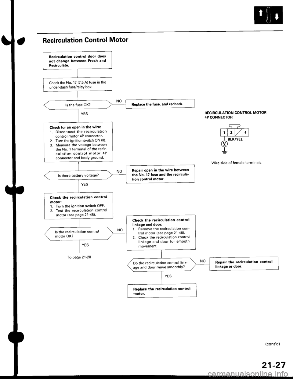
Recirculation control door does
not chango betwe€n Fresh and
Recirculate.
Check the No. l7 (7.5 A) fuse an the
underdash fuse/relay box.
Replace the fuse, and recheck.
Check lor an oPen in the wite:
1. Disconnect the recirculation
control motor 4P connector.
2. Turn the ignition switch ON (ll)
3. Measure the voltage between
the No. 1 terminal of the recir
culation control motor 4P
connector and body ground.
Repair open in the wire between
the No. 17 luse and lhe recircula-
tion control motor.ls there battery voltage?
Check the rccirculation control
motorr']� Turn the ignition switch OFF.
2. Test the recirculation control
motor (see Page 21 48i
Check the recirculation control
linkage and door:1. Remove the recirculation con_
trol motor lsee Page 2l 48).
2. Check the recirculation control
linkage and door for smooth
movement.
Reoair the recirculation conlrol
linkag€ or door.Do the recirculation control link_
age and door move smoothlY?
CONTROL MOTOR
side of temale terminals
RECIRCULATION CONTRC,lP CONNECTOR
q-?--T--T--T-|1l2l/l1l
f BLK/YEt(v)
!
page
(cont'd)
Page 1412 of 2189
Blower Unit
Overhaul
NOTE:
RECIRCULATIONCONTROL MOTORTest, page 21-48
aBefore reassembly. make sure that the recirculation control door and linkage move smoothly without binding.
When attaching the recirculation control motor, make sure its positioning will not allow the recirculation control door
to be pulled too far.
After aftaching the recirculation control motor, connect power and ground, and watch the movement of the recircula-
tion control door.
BLOWERTest, page 2'l 9{'96 - 98 modebl
POWER TRANSISTOR l'99 - 00 modeblTest, page 21-50
Test, page 21'10 ('96 98 models) orpage 21'31 ('99 00 models)
m
MOTOR
2134
Page 1418 of 2189
Temperature Control
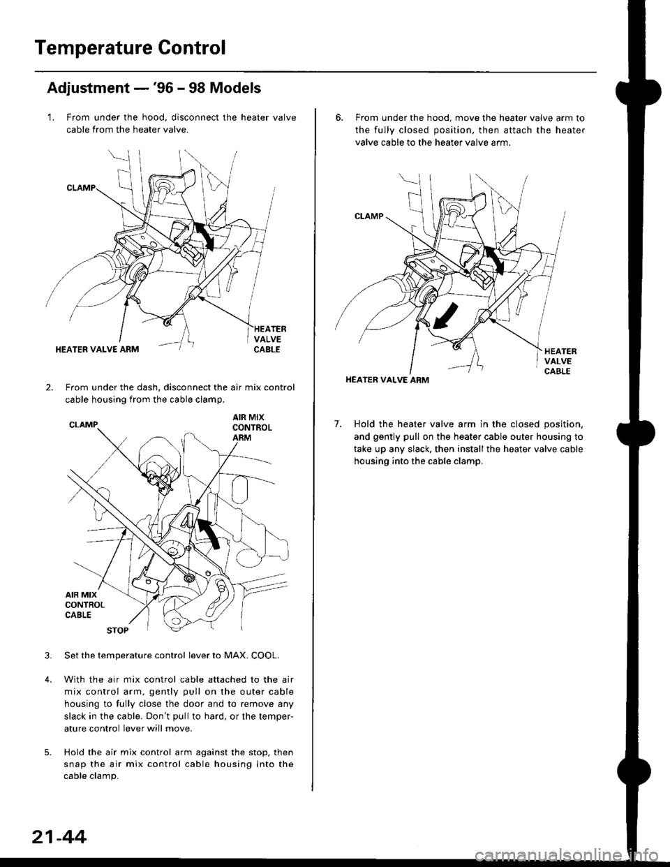
Adjustment -'96 - 98 Models
1. From under the hood, disconnect the heater valve
cable from the heater valve.
TERVALVECABLEHEATER VALVE ARM
2.From under the dash, disconnect the air mix control
cable housing from the cable clamp,
AIR MIXCONTROLARM
3.Set the temperature control lever to MAX. COOL.
With the air mix control cable attached to the air
mix control arm, gently pull on the outer cable
housing to fully close the door and to remove any
slack in the cable. Don't pullto hard, or the temper-
ature control lever will move.
Hold the air mix control arm against the stop. then
snap the air mix control cable housing into the
cable clamp.
21-44
6. From under the hood. move the heater valve arm to
the fully closed position. then attach the heater
valve cable to the heater valve arm.
7. Hold the heater valve arm in the closed position,
and gently pull on the heater cable outer housing to
take up any slack. then install the heater valve cable
housing into the cable clamp.
HEATER VALVE ARM
Page 1420 of 2189
Air Mix Gontrol Motor
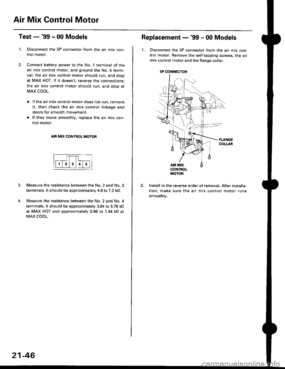
't.
Test -'99 - 00 Models
Disconnect the 5P connector from the air mix con-
trol motor.
Connect battery power to the No. 1 terminal of the
air mix control motor, and ground the No. 5 termi,
nal; the air mix control motor should run, and stop
at MAX HOT. lf it doesn't, reverse the connections;
the air mix control motor should run, and stop at
MAX COOL.
lf the air mix control motor does not run, remove
it, then check the air mix control linkage and
doors for smooth movement.
lf they move smoothly, replace the air mix con-
trol motor.
AIR MIX CONTROL MOTOR
Measure the resistance between the No.2 and No.3
terminals. lt should be approximately 4.8 to 7.2 kO.
Measure the resistance between the No. 2 and No. 4
terminals. lt should be approximately 3.84 to 5.76 kO
at MAX HOT and approximately 0.96 to 1.44 kO at
MAX COOL.
21-46
5P OONNECYOB
Replacement -'99 - 00 Models
1, Disconnect the 5P connector from the air mix con-
trol motor. Remove the self-tapping screws, the airmix control motor and the flange collar.
CONTROLMOTOR
Install in the reverse order of removal. After installa-
tion, make sure the air mix control motor runs
smoothly.
Page 1421 of 2189
Mode Control Motor
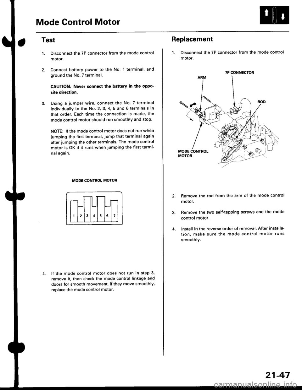
2.
Test
1.
4.
Disconnect the 7P connector from the mode control
motor.
Connect battery power to the No, 1 terminal, and
ground the No.7 terminal,
CAUTION: Never connecl the battery in iho oppo-
site direction.
Using a jumper wire, connect the No. 7 terminal
individually to the No. 2,3, 4,5 and 6 terminals in
that order. Each time the connection is made, the
mode control motor should run smoothly and stop.
NOTE: lf the mode control motor does not run when
jumping the first terminal, jump that terminal again
after jumping the other terminals. The mode control
motor is OK if it runs when jumping the first termi-
nal again.
MODE CONTROL MOTOR
lf the mode control motor does not run in step 3,
remove it. then check the mode control linkage and
doors for smooth movement. lf they move smoothly,
reolace the mode control motor,
Replacement
1. Disconnect the 7P connector from the mode control
motor,
Remove the rod from the arm of the mode control
motor.
Remove the tyvo self-tapping screws and the mode
control motor.
lnstall in the reverse order of removal. After installa'
tion, make sure the mode control motor runs
smoothly.
7P CONNECTOR
21-47
Page 1422 of 2189
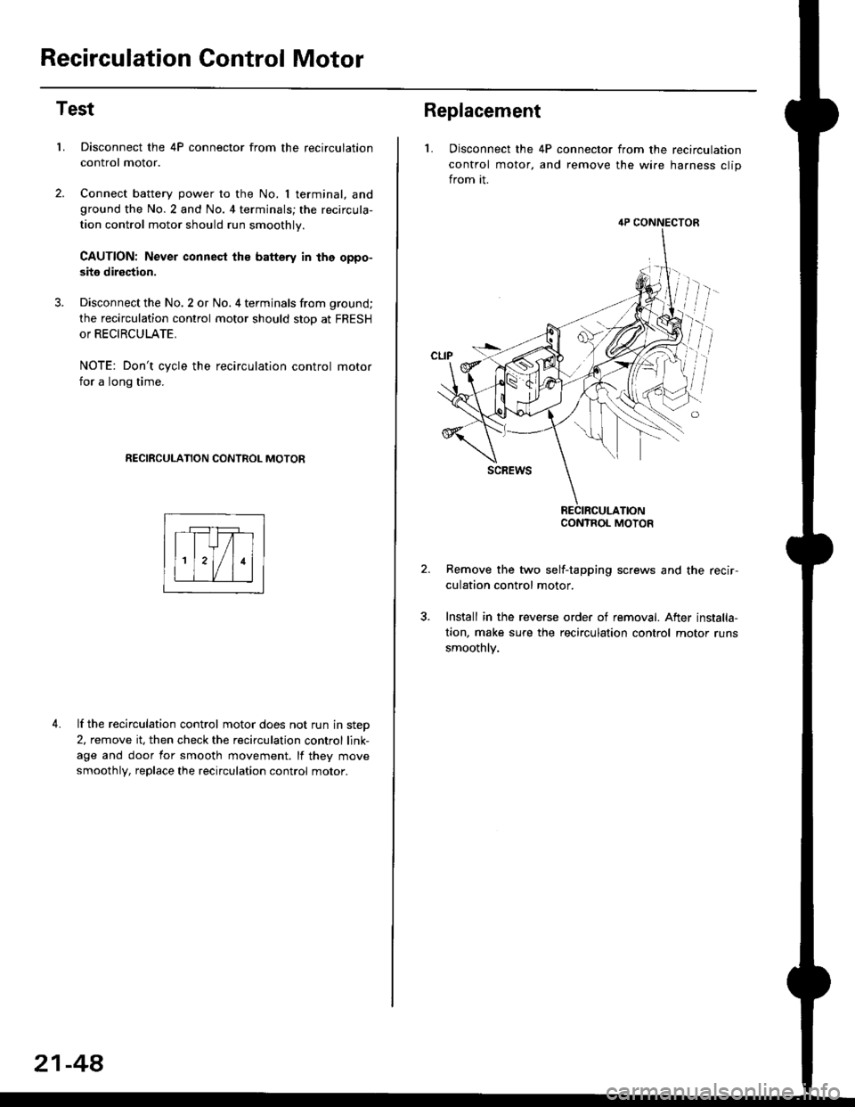
Recirculation Control Motor
Test
LDisconnect the 4P connector from the recirculation
control motor.
Connect battery power to the No. I terminal, andground the No.2 and No. 4 terminals; the recircula-
tion control motor should run smoothly.
CAUTION: Never connest ths battery in the oppo-
site direction.
Disconnect the No. 2 or No. 4 terminals from ground;
the recirculation control motor should stop at FRESH
or RECIRCULATE.
NOTE: Don't cycle the recirculation control motor
for a long time.
RECIRCULATION CONTROL MOTOR
4. lf the recirculation control motor does not run in step
2, remove it, then check the recirculation control link-
age and door for smooth movement. lf they move
smoothly, replace the recirculation control motor.
21-48
Replacement
L Disconnect the 4P connector from the recirculation
control motor, and remove the wire harness clip
from it.
Remove the two self-tapping screws and the recir-
culation control motor.
Install in the reverse order of removal. After installa,
tion, make sure the recirculation control motor runs
smoothly.
4P CONNECTOR
CONTROL MOTOR
Page 1448 of 2189
A/C System Service
Performance Test
The performance test will help determine if the air con-
ditioner system is operating within specifications.
Use only service equipment that is U.L.-listed and is cer-
tified to meet the reouirements of SAE J2210 to remove
HFC-134a (R-134a) from the air conditioner system.
CAUTION: Exposure to air conditionor rofrigerant and
lubricant vapor or mist can irrilalo €yes, nose and
throat. Avoid breathing tho air conditioner rstrigerrnt
and lubricant vapor or mist,
lf accidental system discharge occurs, ventilate work
area before resuming service.
R-134a service equipment or vehicle air conditioner sys-
tems should not be pressure tested or leak tested with
compressed air.
@ some mixtur$ of air and R-134a have been
shown lo b9 combustible rt glgvatad pr€ssur63 and can
resull in tire 01 oxplosion causing inlury ot property
damage. Never uao compre33ed air to pressure t99t R-
134a ssrvico 6quipmsnt or vohicla air conditioner sys-
tems.
Additional health and safety information may be obtained
from the refrigerant and lubricant manufacturers.
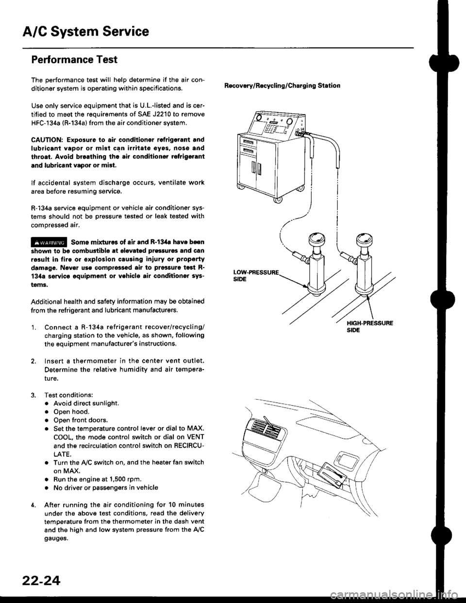
'1. Connect a R-134a refrigerant recover/recycling/
charging station to the vehicle, as shown, following
the equipment manufacturer's instructions.
2. lnsert a thermometer in the center vent outlet.
Determine the relative humidity and air tempera-
ture,
Test conditions:
. Avoid direct sunlight.
. Open hood.
. Open front doors.
. Set the temDerature control lever or dial to MAX,
COOL, the mode control switch or dial on VENT
and the recirculation control switch on RECIRCU-
LATE.
. Turn the A,/C switch on. and the heater fan switch
on MAX.
. Run the engine at 1,500 rpm.
. No driver or passengers in vehicle
After running the air conditioning for 10 minutes
under the above test conditions, read the delivery
temperature from the thermometer in the dash vent
and the high and low system pressure from the A,/C
gauges.
Recovery/Rocycling/Charging Station
22-24