1999 HONDA CIVIC dashboard
[x] Cancel search: dashboardPage 1810 of 2189
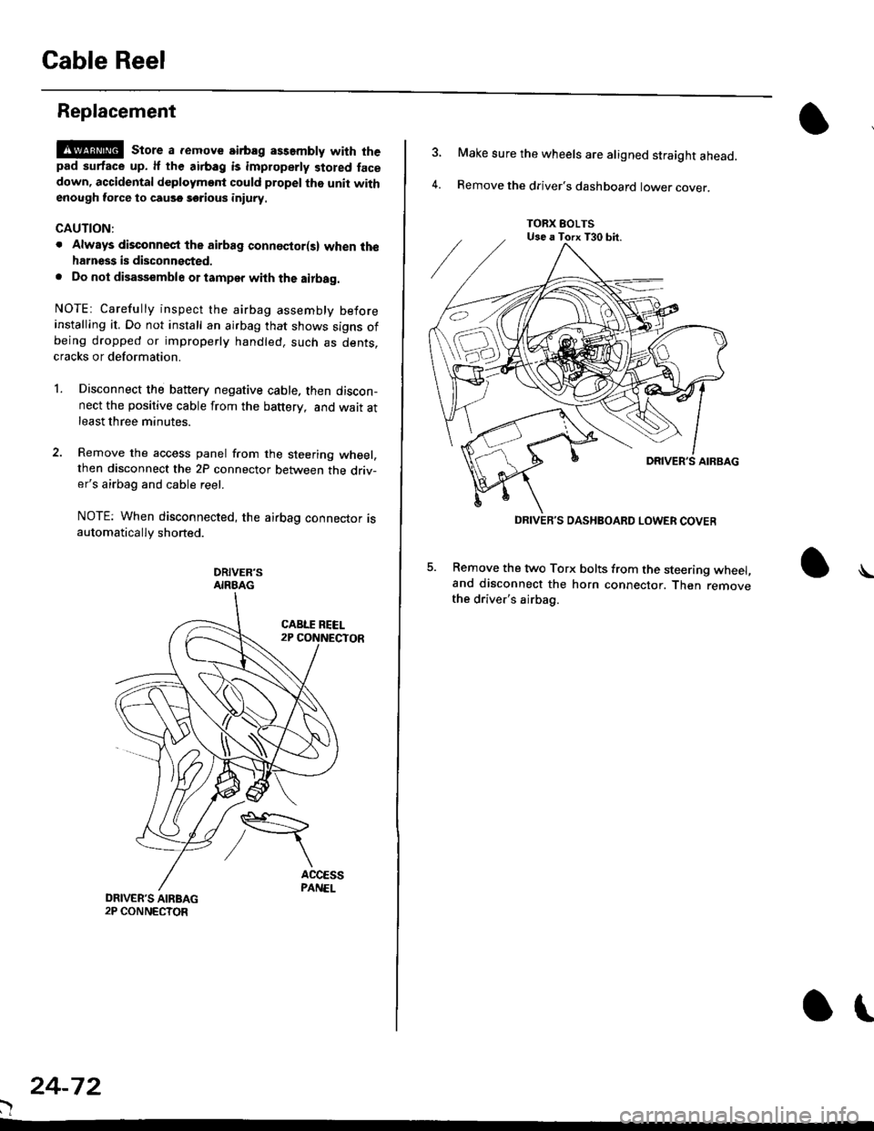
Gable Reel
Replacement
!@@ store a .emove airbag assambly with thepad surtace up. lf the airbag is improperly stored face
down, accidental deploymont could propel the unit withenough force to cause sorious iniury.
CAUTION:
. Alwsys disconnect the airbag connoctor(s) when ih€harness is disconngcted.
. Do not disassemble or tamper with the airbag.
NOTE: Carefully inspect the airbag assembly beforeinstalling it. Do not install an airbag that shows signs ofbeing dropped or improperly handled. such as dents,cracks or deformation.
l.Disconnect the battery negative cable. then discon-nect the positive cable from the battery, and wait atleast three minutes.
Remove the access panel from the steering wheel,then disconnect the 2P connector between the driv-er's airbag and cable reel.
NOTE: When disconnected, the airbag connector isautomatically shorted.
DRIVER'SAIRBAG
)
24-72
or
TORX EOLTSUse a Torx T30 bit.
DRIVEB'S DASHBOARD LOWER COVER
4.
Make sure the wheels are aligned straight ahead.
Remove the driver's dashboard lower cover.
5. Remove the two Torx bolts from the steering wheel,and disconnect the horn connector. Then removethe driver's airbag.
\
Page 1813 of 2189
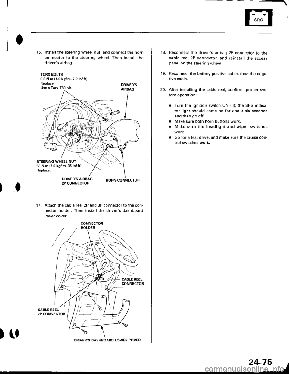
16. Install the steering wheel nut, and connect the horn
connector to the steering wheel. Then install the
driver's airbag.
TORX SOLTS9.8 N m 11.0 kgf m, 7.2 lbtftlReplace.Use a Torx T30 bit.
STEERING WHEEL NUT50 N.m 15.0 kgf.m,36lblft)Replace.
DRIVEB'SAIRBAG
DRIVER'S2P CONNECTOBHORN CONNECTOB
I
17.Attach the cable reel 2P and 3P connector to the con-
nector holder. Then install the driver's dashboard
lower cover.
)UDRIVER'S DASHBOARD LOWER COVER
24-75
18. Reconnect the driver's airbag 2P connector to the
cable reel 2P connector. and reinstall the accesspanel on the steering wheel.
19. Reconnect the battery positive cable, then the nega-
tive cable.
20. After installing the cable reel, confirm proper sys-
tem operation:
Turn the ignition switch ON (ll); the SRS indica-
tor light should come on for about six seconds
and then go off.
Make sure both horn buttons work.
Make sure the headlight and wiper switches
Go for a test drive, and make sure the cruise con
trol switches work.
a
a
Page 1834 of 2189
![HONDA CIVIC 1999 6.G Workshop Manual Fuse/Relay Information
- Under-dash Fuse/Relay Box
Front View
c712(To moonroof wire harness)
. : Canadai : Not UsedO : C926 loprion (+B)l
@ : C927 loption (dash lights)]
O : C928 [Option (ACC]I
@ : C9 HONDA CIVIC 1999 6.G Workshop Manual Fuse/Relay Information
- Under-dash Fuse/Relay Box
Front View
c712(To moonroof wire harness)
. : Canadai : Not UsedO : C926 loprion (+B)l
@ : C927 loption (dash lights)]
O : C928 [Option (ACC]I
@ : C9](/manual-img/13/6068/w960_6068-1833.png)
Fuse/Relay Information
- Under-dash Fuse/Relay Box
Front View
c712(To moonroof wire harness)
. : Canadai : Not UsedO : C926 loprion (+B)l
@ : C927 loption (dash lights)]
O : C928 [Option (ACC]I
@ : C929 loption (lc2)l
Rear View
css2
c421(To main wire harness)
c801CI-o SRS main harness)
c501(To dashboard wire harness)
^ : Not used ('96-'97 models)
c913(To ignition switch)
INTEGRATEDCONTROL UNITCONNECTOR A
c419Oo main wire harness)
REAR WINDOWDEFOGGER RELAY
TURN SIGNAUHAZARD RELAY
c423(To main wire harness)
co
c422(To main wire harness)
POWERwtNDowRELAY
c551flo lloor wire harness)c439 f96.'97 MODELSand ALL GX MOOELS)(To main wire harness)
T1 T-t T"l T"t r-r r-'l T1 F n r-l r-l r'123 24 25 26 27 28 29 30 31 32 33I-J I.J I.J IJ IJ IJ LJ IJ IJ I.J I.J I-I
r"1 r-t r-t T-l r"l r-r Fl r:1 n rJ n -12 13 14 t5 16 17 t8 19 2A 2t 22LI I.J L! LI tJ LJ (J LI IJ IJ T-I I.J
n r:l rj.l |-l T"l Tl r:t n r-l |;.l r-r r-l1 2 3 4 5 6 7 I 9 10 11LI LI IJ LJ LJ I,J T-I I.J TJ IJ I.-I tJ
c420(To main wire harness)
6
(To floor wire harness)
Page 1953 of 2189
- How the Circuit Works
'96198 Models
The air delivery system directs the flow of air used
by the heater and air conditioner systems.
Mode Selection
Mode selection is controlled by the mode switches
in the heater control panel and the mode control
motor. When you select a specific mode, voltage is
applied through the dimming circuit to the LED,
which comes on, indicating the mode selected.
Ground is orovided to the mode control motor
though that mode switch. The motor then runs until
the air control door reaches the proper position.
Fresh/Recirculation 56lection
When you press the fresh or recirculation button, a
ground signal is sent from the heater control panel
to the recirculation control motor. The motor then
runs until the recirculation door reaches the proper
position. Battery voltage is also applied through the
dimming circuit to the corresponding LED, and the
LED comes on.
Refer to the Service Manual (Section 21, Heater) for
specitic tests or troubleshooting proc€dures.
'99J00 Models
The heater control panel receives battery voltage at
all times through fuse 47. With the ignition switch in
ON (ll), voltage is supplied to the heater control
panel through fuse 17. The control panel is
grounded at G402.
The heater control panel controls the air delivery
motors, and supplies a 5 VDC reterence voltage to
the air mixture control motor.
The air mixture and mode control motors each
receive inputs trom the heater control panel. The air
mix motor regulates the mixture of cold and hot air
by varying the position of the heater-evaporator doot
The mode control motor controls the direction and
volume of outlet air. The air flow can be directed to
the dashboard vents or the corner vents.
Both the air mixture control molor and mode control
motor are grounded by the h€aler control panel.
The recirculation control motor receives battery
voltage through fuso 17 when the ignition swilch is
in ON (ll). lt regulates the position of the fresh/recirc
door, and is controlled by two position inputs from
the heater control panel ("Recirc" and "Fresh").
Refer to the Service Manual (Section 21, Heater) tor
specific tests or troubleshooting procedures.
61-3
Page 2116 of 2189
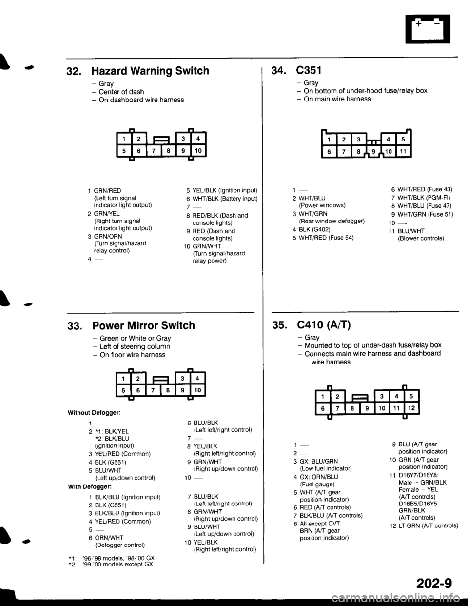
-32. Hazard Warning Switch
- Gray- Center ol dash- On dashboard wire harness
l GRN/RED(Left turn signalindicator light output)
2 GRN/YEL(Right turn signalindicator light output)
3 GRN/ORN
Ourn signal/hazardrelay control)
4
5 YEL/BLK (lgnition input)
6 WHT/BLK (Battery inpul)
7
8 RED/BLK (Dash andconsole lights)g RED (Dash andconsole lights)
1O GRNAVHT(Turn signal/hazardrelay power)
34. C351
- Gray- On bottom of under-hood fuse/relay box- On main wire harness
14
67I I9 I1011
2 WHT/BLU(Power windows)
3 WHT/GRN(Rear window defogger)
4 BLK (G402)
5 WHT/FED (Fuse 54)
6 WHT/RED (Fuse 43)
7 WHT/BLK (PGM-Fl)
8 WHT/BLU (Fuse 47)
I WHT/GRN (Fuse 51)
10 _
11 BLUAVHT(Blower controls)
33,
Without Oelogger:
1
2 *1: BLK,|YEL*2r BLKBLU(lgnition input)
3 YEURED (Common)
4 BLK (G551)
5 8LU,ryVHT(Left up/down control)
With Delogger:
1 BLIVBLU (lgnition input)
2 BLK (G551)
3 BLIVBLU (lgnition inPut)
4 YEURED (Common)
6 ORNMHT(Detogger control)
'96198 models, '98-'00 GX'99 00 models except GX
Power Mirror Switch
- Green or White or Gray- Left of steering column- On floor wire harness
6 BLU/BLK(Left left/right control)
8 YEUBLK(Right left/right control)
9 GRNAVHT(Right up/down control)
10
7 BLU/BLK(Lett left/right control)
8 GRNMHT(Right up/down control)
9 BLU/WHT(Lett up/down control)
1O YEL/BLK(Right left/right connol)
I
-
202-9
35. C41o (A/T)
- Gray- lilounted to top of underdash {use/relay box- Connects main wire harness and dashboard
wtre narness
2
3 GX: BLU/GRN
{Low fuel indicator)
4 GX: ORN/BLU(Fuelgauge)
5 WHT (A/T gearposition indicator)
6 RED (A,/T controls)
7 BLI(BLU (A,rT controls)
8 All except CVT:BRN (AiT gearposition indicator)
I BLU (Aft gearposition indicator)
10 GRN (A/I gearposition indicator)
11 D16Y7/D16Y8:Male - GRN/BLKFemale YEL(A/T conkols)D1685/D16Y5:GRN/BLK(M controls)
12 LT GRN (A/T controls)
Page 2121 of 2189
Gonnector Views (conrd)
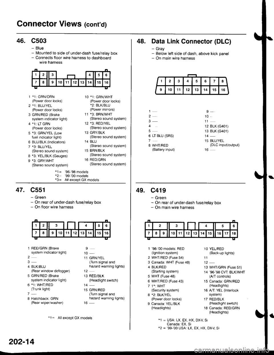
46. C503
B
9
*1: GBN/ORN(Power door locks)*1r BLU|/EL(Power door locks)
GRN/RED (Brake
system indicator light)*1r LT GRN(Power door locks)*3: GRN/YEL (Lowfuel indicator light)
BLU/BLK (lndicators)*3: BLU/YEL(Stereo sound system)*3: YEUBLK (Gauges)*3: GRY/WHT(Stereo sound system)
10 *1: GRNAVHT(Power door locks)*2: BL(BLU(Power mirfors)
11 *3: BRNMHT(Stereo sound system)
12 *3: RED/YEL(Stereo sound system)
13 GRY/BLK(Stereo sound system)
14 BLU(Stereo sound system)
15 BRN/BLK(Stereo sound system)
16 RED/GBN(Stereo sound system)
- Blue- lvlounted to side of under-dash fuse/relay box- Connects floor wire harness to dashboardwtre narness
1
2
3
5
6
7
*1= '96-'98 models*2: '99-'00 models*3= All except GX models
48. Data Link Connector (DLC)
- Gray- Below left side of dash, above kick panel- On main wire harness
4
6 LT BLU (SRS)
7
8 WHT/BED(Battery input)
9
10
12 BLK (G401)
13 BLK (G401)
14
15 BLU/YEL(DLC inpuVoutput)
47. C551
- Green- On rear of under-dash tuse/relay box- On floor wire harness
1 BED/GRN (Brake
system indicator light)
2
4 BLI(BLU(Rear window defogger)
5 GBN/RED (Brake
system indicator llght)
6 *1: WHT/RED(Trunk light)
7
8 Hatchback: GBN(Rear wiper/washer)
9
10
11 GRN/YEL(Turn signal andhazard warning lights)
13 RED/BLK(Headlight switch)
14
15 GRN/RED(Turn signal andhazard warning lights)
202-14
*1= Allexcept GX models
49. C419
- Green- On rear of under-dash fuse/relay box- On main wire harness
1 '98''00 models: RED(lgnition system)
2 WHT/RED (Fuse s4)
3 Canada: WHT (Fuse 48)
4 BLI(RED(Starting system)
5 WHT (Fuse 48)
6 WHT/RED (Fuse 43)
7 1*: WHT(Security system)
I *2: BLK,TYEL
{Power door locks)
I Canada: YEL/BLK(Headlights)
1O YEURED(Back up lights)
11
13 WHT/GRN (Fuse 51)
14 '96-'98 CVT: BLKWHT(A/T controls)
15 Canada: GRN/RED(Headlights)
16 A/Ti YEL (lnterlock
system)
17 RED/BLK(Headlight switch)
18 Canada: RED/GRN(Headlights)
"1 = USA: LX, EX, HX, DX-V SiCanada: EX, Si12 = '99100 USA: LX, EX, HX, DX-V Si
Page 2123 of 2189
Connector Views (cont'd)
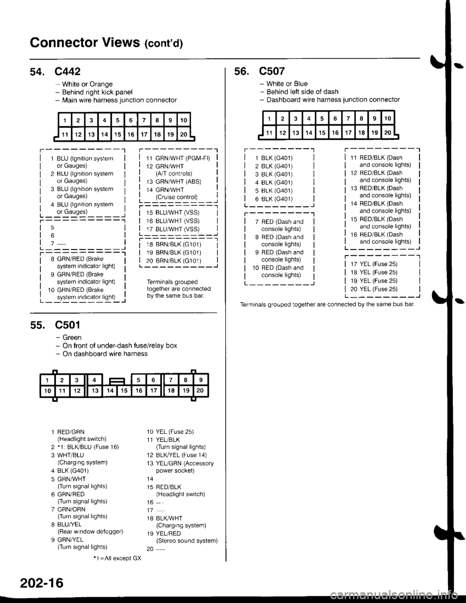
54. c442
- White or Orange- Behind right kick panel- l\,lain wire harness junction connector
r---------Tr---------"1
1 BLU (lgnition systemor Gauges)
2 BLU (lgnition syslemor Gauges)
3 BLU (lgnition systemor Gauges)
4 BLU (lgnition system
L_ or causes)L_-:-:::'-'�____Jt-----------1
11 GRN/WHT (PGM-FD
12 GRN/WHT(A/T controls)
13 GRNMHT (ABS)
14 GRNMHT
L_ lc,r'." .oIr"D_ _ _.jr----------_l
5
6
7L---------JT----------l8 GRN/RED (Brake
system indicator light)
9 GRN/RED (Brake
system indicator light)
10 GRN/RED (Brake
_ system indicator ligh0 -..1
| 15 BLUMHT (vSS) |I 16 BLUMHT (VSS) I
L T?_BLUSTrySS)--..]
l--------- - -l
| 18 BFN/BLK (G101) I| 19 BBN/BLK (G101) || 20 BRN/BLK (c101) |L---------J
Terminals groupedtogether are connectedby the same bus bar.
55. C501
- Green- On tront of under-dash tuse/relay box- On dashboard wire harness
l RED/GFN(Headlight switch)
2 *1 : BLKBLU (Fuse 16)
3 WHT/BLU(Charging systern)
4 BLK (G401)
5 GRNMHT(Turn signal lights)
6 GRN/RED(Turn signal lights)
7 GRN/ORN(Turn signal lights)
8 8LU/YEL(Rear w ndow delogger)
9 GFN/YEL(Turn signal lights)
'10 YEL (Fuse 25)
11 YEL/BLK(Turn signal lights)
12 BLKTYEL (Fuse 14)
13 YEUGRN (Accessorypower socket)
15 RED/BLK(Headlight switch)
1B BLK/WHT(Charglng system)
19 YEL/RED(Stereo sound system)
20
202-16
-1 =All e),cept GX
s6. c507
- White or Blue- Behind left side oJ dash- Dashboard wire harness junction connector
r --------'lT---------l
7 BED (Dash andconsole lights)
B BED (Dash andconsole lights)
I RED (Dash andconsole lights)
10 RFD (Dash andconsole lights)
11 RED/BLK (Dash
and console lights)
12 RED/8LK (Dash
and console lights)
13 RED/BLK {Dashand console lights)
14 RED/BLK (Dash
and console lights)
15 RED/BLK (Dash
and console lights)
16 RED/BLK (Dash
and console lights)L--------J
T--------T
L---_---_J
1 BLK (G401)
2 BLK (G401)
3 8LK {G401)4 8LK (G401)
5 BLK (G401)
6 8LK (G401)L________J
T--------"1
17 YEL (Fuse 25)
18 YEL (Fuse 25)
19 YEL (Fuse 25)
20 YEL (Fuse 25)L--------J
Term nals grouped together are connected by the same bus bat
Page 2127 of 2189
Connector Views (cont'd)
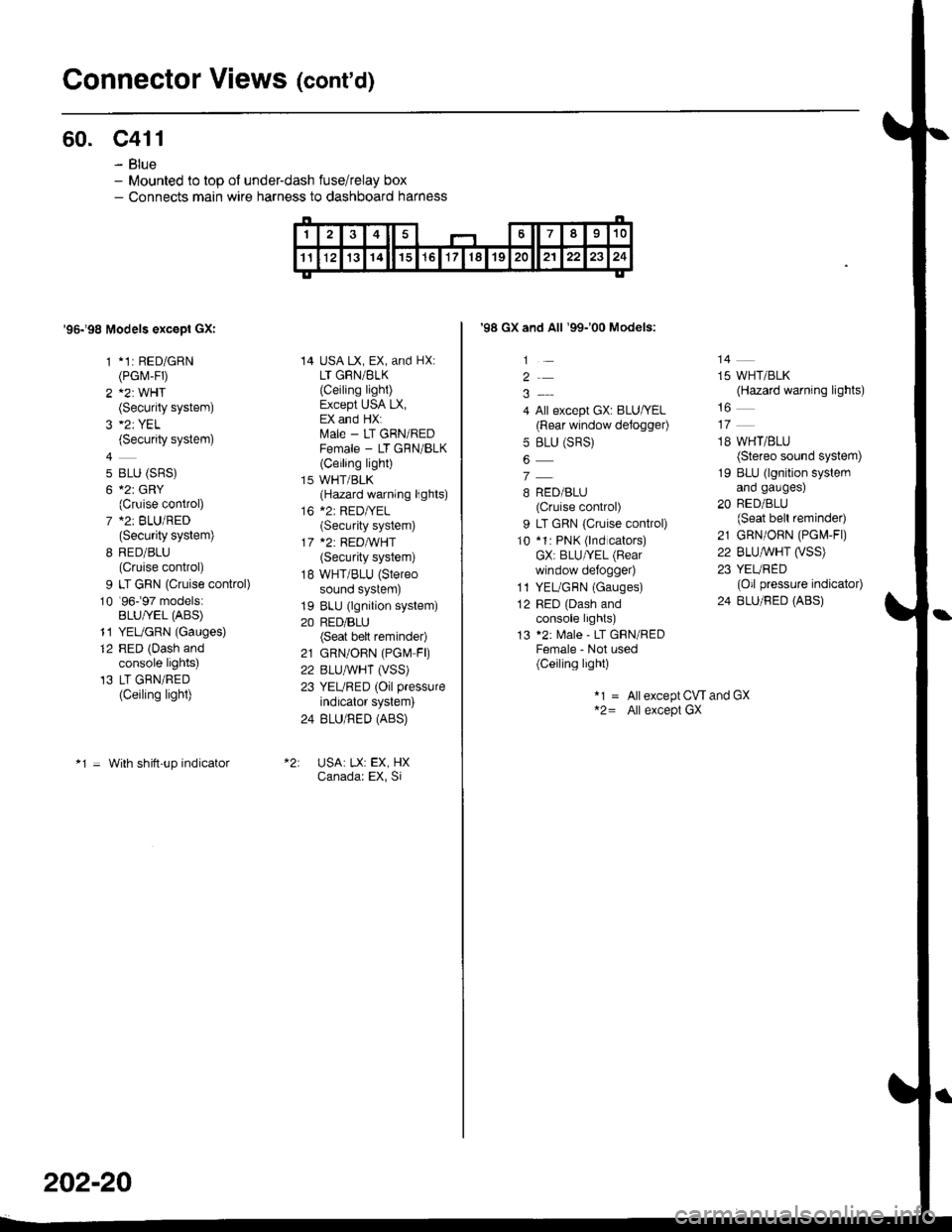
60. c411
- Blue- Mounted to top ol under-dash fuse/relay box- Connects main wire harness to dashboard harness
'95198 Models excepl GXI
1 *1: RED/GRN(PGrvr-FD
2 A2: WHT(Security system)
(Security system)
4
5 BLU (SRS)
6 *2r GRY(Cruise control)
7 *2: BLU/RED(Security system)
8 RED/BLU(Cruise control)
9 LT GRN (Cruise control)
10 '96-�97 models:BLU/YEL (ABS)
11 YEUGRN (Gauges)
12 RED (Dash andconsole lights)'13 LT GRN/RED(Ceiling light)
*1 = With shitt-up indicator
14 USA LX, EX, and HX:LT GRN/BLK
{Ceiling light)Except USA LX,EX and HX:ftrale - LT GRN/REDFemale - LT GRN/BLK(Ceiling light)
15 WHT/BLK(Hazard warning lights)
16 *2: RED|YEL(Security system)
17 *2: REDA/VHT(Security system)
18 WHT/BLU (Stereo
sound system)
19 BLU (lgnition system)
20 RED/BLU(Seat bett reminder)
21 GRN/OBN (PGN4 FD
22 BLUAVHT (VSS)
23 YEURED (Oil pressure
indicator system)
24 BLU/RED (ABS)
USA: LX: EX, HXCanadar EX, Si
202-20
'98 GX and All '99-'00 Models:
1
2
4 All except GX: BLU/YEL(Rear window defogger)
5 BLU (SRS)
7
B RED/BLU(Cruise control)
9 LT GRN {Cruise control)
10 *1: PNK (lnd cators)GX: BLU/YEL (Bear
window defo9ger)
1l YEL/GBN (Gauges)
12 RED (Dash andconsole lights)
13 *2: Male - LT GRN/REDFemale - Not used(Ceiling light)
14
15 WHT/BLK(Hazard warning lights)
18 WHT/BLU(Stereo sound system)
19 BLU (lgnition systemano gaugesl
20 RED/BLU(Seat bell reminder)
21 GRN/ORN (PG[,4-Fl)
22 BLU,ryVHT O/SS)23 YEURED(Oil pressure indicator)
24 BLU/RED (ABS)
*1 = Allexcept CW and GX*2= All except GX