Page 1477 of 2189
Relay and Control Unit Locations
Engine Compartment
UNDER.HOOD ABS
FUSE/RELAY BOX
CONDENSER FAN
RELAY
UNDER.HOODFUSE/RELAY BOX
MOTORRELAY
A/C COMPRESSORCLUTCH RELAY
RADIATORFAN RELAY
ELD UNIT
t:
tr
tr
uI Il I tl I
23-7
Page 1484 of 2189
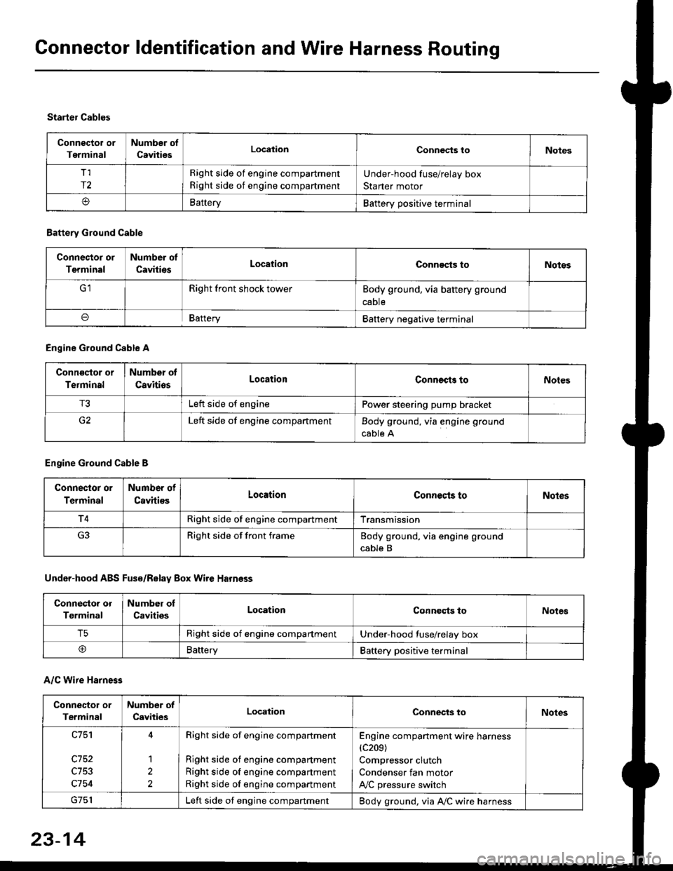
Connector ldentification and Wire Harness Routing
Connector or
Terminal
Number of
CavitiesLocalionConnec{s toNotes
T,I
r2
Right side of engine compartment
Right side of engine compartment
Under-hood fuse/relay box
Starter motor
BatteryBattery positive terminal
Starter Cables
A/C Wire Harness
Battery Ground Cable
Connector or
Terminal
Number of
CavitiesLocationConn€cts toNotos
Right front shock towerBody ground, via battery ground
caDte
oBafteryBattery negative terminal
Engine Ground Cable A
Conn€qtor or
Terminal
Number ot
CavitiosLocationConnects toNoles
T3Left side of enginePower steering pump bracket
G2Left side of engine compartmentBody ground, via engine ground
cable A
Engine Ground Cable B
Connector or
Terminal
Number of
CavitiesLocationConnecls toNoles
T4Right side of engine compartmentTransmission
Right side of front frameBody ground, via engine ground
cable B
Under-hood ABS Fusa/Relay Box Wire Harness
Connector or
Tgrminal
Number oI
CavitiesLocationConneqts toNotes
T5Right side of engine compartmentUnder-hood fuse/relay box
@BaneryBattery positive terminal
Connector or
Terminal
Number of
CavitiesLocationConnects toNotes
c753
c754
1
2
Right side of engine compartment
Right side of engine compartment
Right side of engine compartment
Right side of engine compartment
Engine compartment wire harness(c209)
Compressor clutch
Condenser fan motor
A,/C pressure switch
Left side of engine compartmentBody ground, via A,/C wire harness
23-14
Page 1498 of 2189
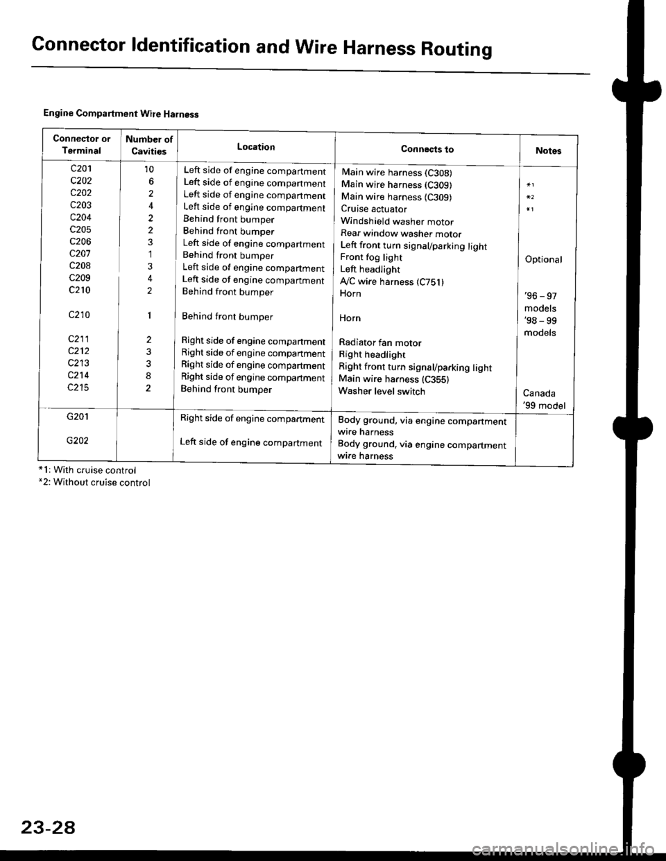
Connector ldentification and WireHarness Routing
Engine Compartment Wire Harness
conneqtor of
Terminal
Number of
CavitiesLocationConnects toNotes
c201
c202
c202
c203
c204
c205
c206
c207
c208
c209
c210
c210
c211
c212
c213
c214
c215
10
6
2
2
2
1
3
2
1
2
8
Left side of engine companment
Left side of engine companment
Left side of engine companment
Left side of engine compartment
Behind front bumper
Behind front bumper
Left side of engine compartment
Behind front bumper
Left side of engine compartment
Left side of engine companment
Behind front bumper
Behind front bumper
Right side of engine compartment
Right side of engine compartment
Right side of engine compartment
Right side of engine compartment
Behind front bumper
Main wire harness (C308)
Main wire harness (C309)
Main wire harness {C309)Cruise actuator
Windshield washer motor
Rear window washer motor
Left front turn signal/parking lightFront fog light
Left headlight
Ay'C wire harness 1C751)Horn
HOrn
Radiator fan motor
Right headlight
Right front turn signal/parking lightMain wire harness (C355)
Washer level switch
Optional
'96 - 97
models'98 - 99
models
Canada'99 model
G201
G202
Right side of engine compartment
Left side of engine compartment
Body ground, via engine compartmentwire harness
Body ground, via engine compartmentwrre harness*1r With cruise control*2: Without cruise control
23-2A
Page 1575 of 2189
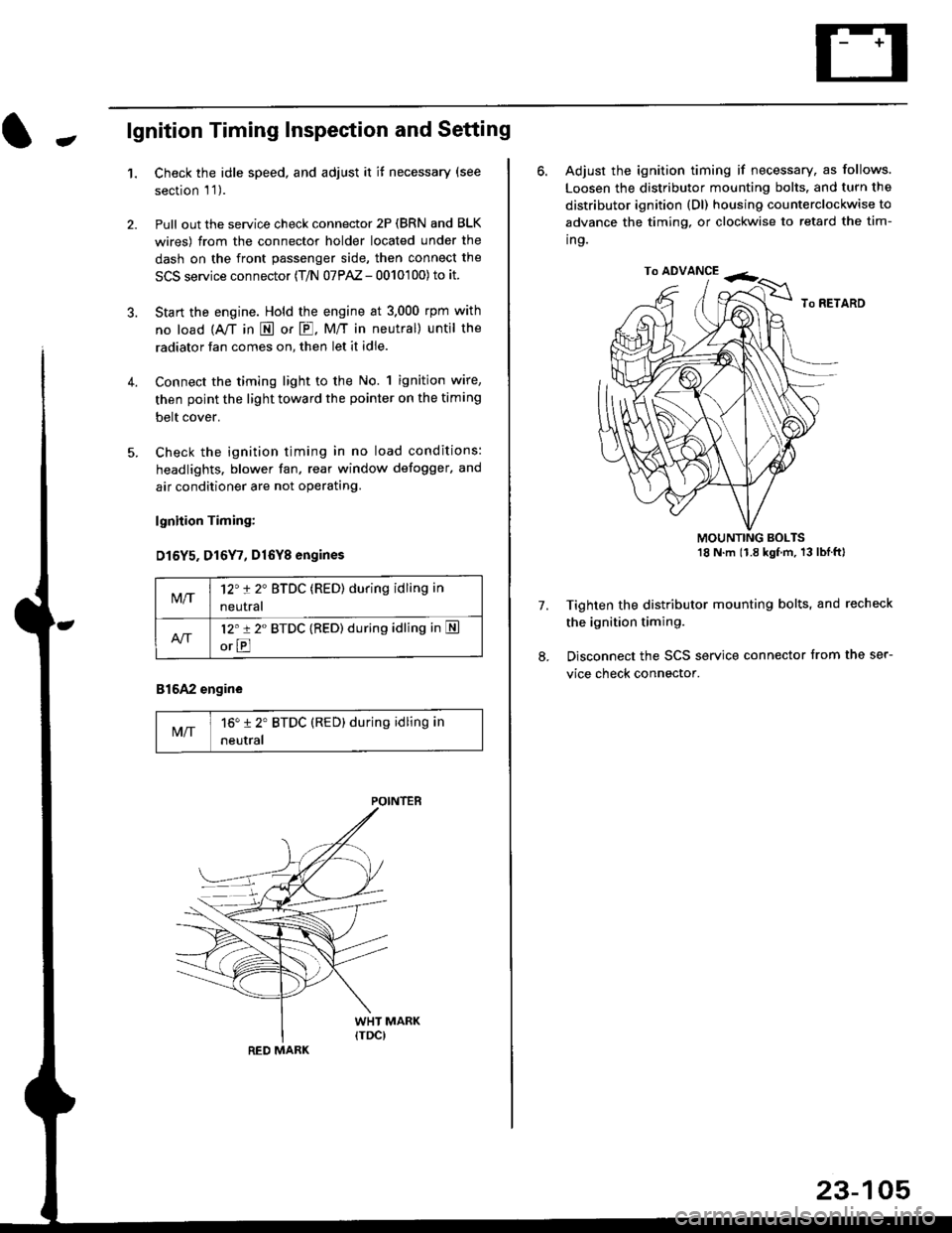
-lgnition Timing Inspection and Setting
1.Check the idle speed, and adjust it it necessary (see
section 'l '1 ).
Pull out the service check connector 2P (BRN and BLK
wires) from the connector holder located under the
dash on the front passenger side, then connect the
SCS service connector (T/N 07PAZ - 0010'100) to it.
Start the engine. Hold the engine at 3.000 rpm with
no load {A,/T in E or E. M/T in neutral) until the
radiator fan comes on, then let it idle.
Connect the timing light to the No. 1 ignition wire,
then point the light toward the pointer on the timing
belt cover.
Check the ignition timing in no load conditions:
headlights. blower fan, rear window defogger, and
air conditioner are not operating.
lgnhion Timing:
D15Y5. D16Y7, Dl6Yg engines
816A2 engine
MIT16" 12' BTDC (RED) during idling in
neutral
M/T12't 2" BTDC (RED) during idling in
neutral
l2'r 2" BTDC {RED) during idling in S
orE
POINTEB
RED MARK
23-105
ro ADVANCE -<;,
6. Adjust the ignition timing if necessary, as follows.
Loosen the distributor mounting bolts. and turn the
distributor ignition (Dl) housing counterclockwise to
advance the timing, or clockwise to retard the tim-
ing.
MOUNTING BOLTS18 N'm (1.8 kgfm, 13lblftl
Tighten the distributor mounting bolts, and recheck
the ignition timing.
Disconnect the SCS service connector from the ser-
vice check connector.
7.
Page 1588 of 2189
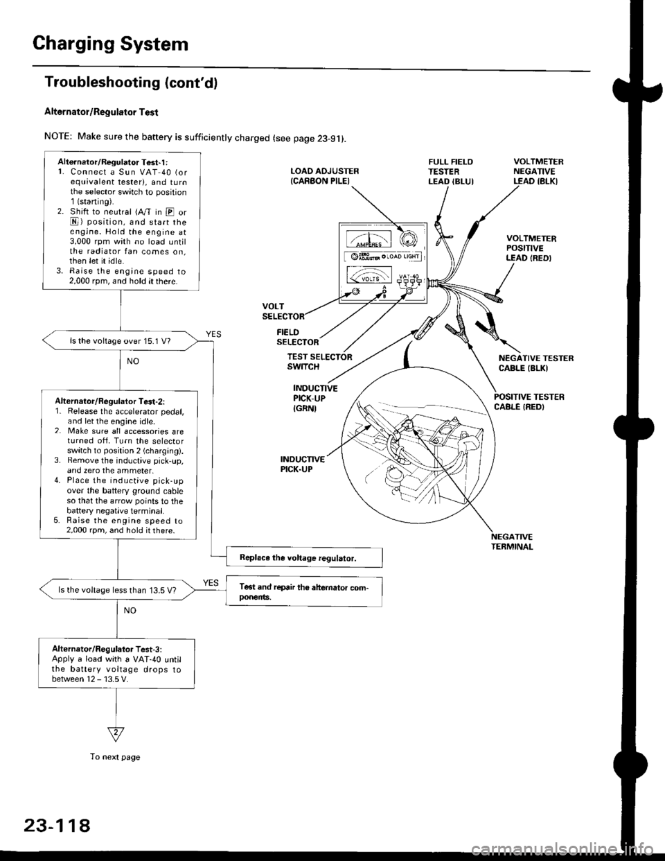
Charging System
Troubleshooting (cont'd)
Alt6rnator/Regulator Test
NOTE: Make sure the baftery is sufficiently charged (see page 23-9j).
FIELDSELECTOR
LOAD AOJUSTER{CARAON PILEI
FULL FIELOTESTERLEAD IBLUI
VOLTMETERNEGATIVELEAD IBLKI
VOLTMETERPOStTtVELEAD (REDI
NEGATIVE TESTERCABLE IBLKI
POSITIVE TESTERCABLE IREDI
TEST SELECTORswrTcH
INDUCTIVEPICK-UP
IGRNI
INDUCNVEPICK.UP
TIVETEBMINAL
Alte.nator/Regulator Test'1 :L Connect a Sun VAT 40 (orequivalent tester), and tu rnthe selector sw;tch to position1(staning).2. Shift to neutral (A/T in E orE) position, and start theengine. Hold the engine at3,000 rpm with no load untilthe radiator fan comes on,then let it idle.3. Raise the engine speed to2,000 rpm, and hold it there.
ls the voltage over 15.1 V?
Alternalor/Regulator Te3t-2:1. Release the accelerator pedal,and let the engine idle.2. Make sure all accessories areturned ofi. Turn the selectorswitch to position 2 (charging).3. Bemove the inductive pick-up,and zero the ammeter,4. Place the inductive pick-upover the battery ground cableso that the arrow points to thebattery negatlve terminal.5. Raise the engine speed to2,000 rpm, and hold it there.
ls the voltage less than 13.5 V?
Alternator/Regulator Test-3:Apply a load with a VAT-40 untilthe battery voltage drops tobetween 12 - 13.5 V.
tffil rCI
[ @lBt* . ,*n 'aHrl
L-;-;l rs-
23-11A
To next page
Page 1596 of 2189
Fan Controls
Component Location Index
UNDER.HOOO
CONDENSER FAN RELAYTest, page 23-87
RADIATOR FAN RELAYTest, page 23 87
CONDENSERFAN MOTOR
TOR FAN MOTORRemoval, section 10
ENGINE COOLANTTEMPERATURE (ECTI
swtTcHRemoval, section 10Test, section l0
t lt lt lt tt l
tlTtlnr-l
mU!L-Jfl_l'1 - f-t t-_l -
I L--J L__J LJ f-----"1
o
^o
o"l
23-126
Page 1718 of 2189
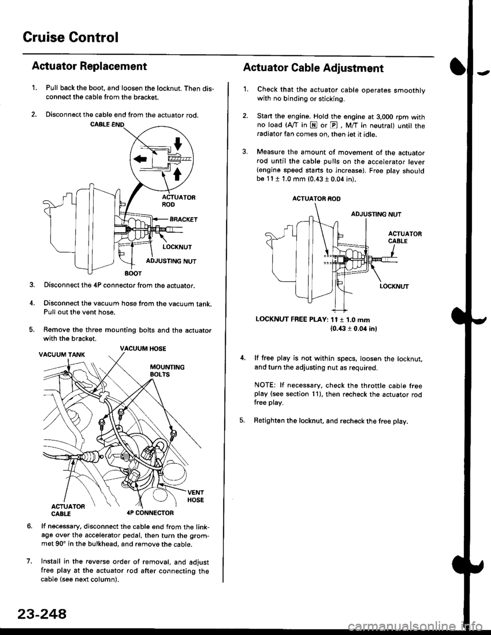
Cruise Control
t
D=
t
Astuator Replacement
1.Pull back the boot, and loosen the locknut. Then dis-
connect the cable from the bracket.
Disconnect the cable end from the actuator rod.
Disconnect the 4P connector from the actuator.
Disconnect the vacuum hosa from the vacuum tank.Pull out the vent hose.
Remove the three mounting bolts and the actuator
with the bracket.
CABTI aP CONNECTOR
lf necessary, disconnect the cable end from the link-age over the accelerator pedal, then turn the grom-
met 90' in the bulkhead, and remove the cable,
Install in the revers€ order of removal, and adjust
free play at the actuator rod after connecting thecable (see ne)d column).
7.
VACUUM HOSE
23-244
1.
Actuator Cable Adjustment
Check that the actuator cable operates smoothlywith no binding or sticking.
Stan the engine. Hold the engine at 3,000 rpm withno load (Afl'in N or E, M/T in neutral) untit theradiator fan comes on, then let it idle.
Measure the amount of movement of the actuato.rod until the cable pulls on the accelerator lever(engine speed starts to increase). Free Dlay shouldbe 11 t 1.0 mm (0.43 I 0.04 in).
LOCKNUT FREE PLAY: 11 1 1.0 mm
{o.i|:l r 0.oit in}
lf free play is not within specs, loosen the locknut,
and turn the adjusting nut as required.
NOTE: lf necessary. check the throttle cable freeplay (see section 11). then recheck the actuator rodfree play.
Retighten the locknut, and recheck the free play.
ACTUATOR ROD
Page 1817 of 2189

Contents
How to Use This Manual ICircuit Schematics (see Circuit Index)Fuse/Relaylnformation 6Ground-to-Componentslndex 6-6ComponentLocationPhotooraohs 201Conriector Views 202
Circuit Index
Accessory power socket 155Air conditionerAir delivery'96198 models 61'99-'00 models 61-2Blower controls'96198 models 60'99100 models 60-1Compressor controls 62Fans 63Anti-lock brake system (ABS) 44A/T gear position indicatorCVT 89All except CVT 89-1Automatic transmission controlsAll '96-'98 models except CVT and GX 39All '99100 models except CVT 39-8All GX models 39-8'96-'�98 CVT 39-4'99100 cw 39-12Back-up lightsCoupe and Sedan 110Hatchback l'10-1Brake lightsAll Coupes and'96-'98 Sedans 110-15'99-'00 Sedans 110-16Hatchback 110-17Brake system indicator light'96198 models 7'1'99100 models 71-1Ceiling light 114-3Charging system 22Condenser fan 63Console lights 114Cruise control 34Dash lights 114Daytime running lights 110- 13Engine coolant temperature gauge 81-1Fog lights 110-10Front parking lights 110-2Fuel gauge 81-1Fuse/relay boxUnder-dash 6Under-hood 6-4Underhood ABS 6-3Gauges 81Ground distribution 14Ground-to-Componentslndex 6-6Hazard warning lightsAll except '99100 Sedans 110-6'99100 Sedans 110-8Headlights 110-12Headlight switch 100Heater - See Air ConditionerHorn'96197 models 40'98 model 40-1'99100 models 40-2lgnition key reminder 73lgnition systemAll '96198 models except Dl685 20All '99100 models except D16Y5 with Mn 2O-2All D1685 engines 20-2'99-'00 D 16Y5 with M/T 20
lndicators 80Integrated control unit 70lnterlock systemAll except'96J98 CVT 138'96198CVT 138-1License plate lightsAll Coupes and '96-'98 Sedans I l0-3'99100 Sedans 1 10-4Hatchback 110-5Low fuel indicator light 74Moonrool'96197 models |22'98-'00 models 122-1Odometer 81Oil pressure indicator light 80-3Power distributionBattery to ignition switch, fuses, and relaysFuses to relays and components 10-2Power door locksAll models without keyless entry 130'96-'98 models with keyless entry 130-2'99100 models with keyless entry 130-12Power mirrorsWithout detogger 141With defogger '141-2
Power windows 120Programmed fuel injection system (PGNr-Fl)All '96-98 models except D1685 23All '99-'00 models except D16Y5with M/T and D1685 24All D1685 engines 25'99100 D16Y5 with M/T 23Radiator fan 63Rear window defogger'96-,98 models 64'99100 models 64-1Seat belt reminder 73Security system'96.'98 USA HX, LX, EX 133'96-'98 Canada EX, Si 133'99TOO USA HX, LX, EX, DX.V Si 133-4'99100 Canada EX, Si 133-4All CX and DX models 133-8Speedometer 81Starting systemA./T (All except Dl685) 21A"/r (D16Bs) 21-1Manualtransmission 21-2Slereo sound system 150Supplemental rastraint system (SRS) 47Tachometer 81TailliqhtsAllboupes and'96-'98 Sedans 110-3'99100 Sedans 1 10-4Hatchback 110-5Trunk light 114-3Turn signal lightsAll except'99100 Sedans 110-6'99-'00 Sedans 1 10-8Vehicle speed sensor (VSS) 33Wiper/washerFront 91Rear 92
10