Page 461 of 2189

ldle Control System
ldle ControlSystem
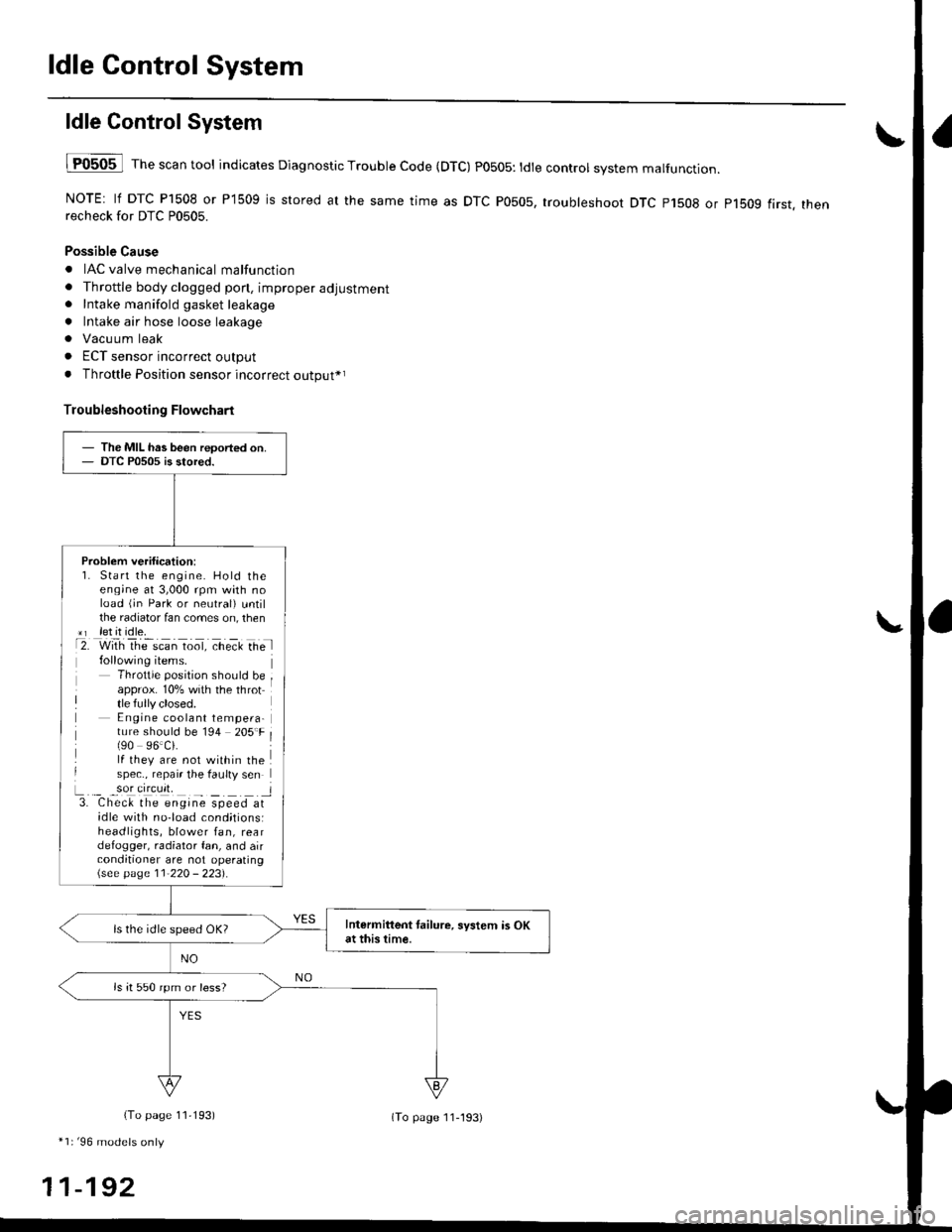
lF0505 l Th" """n tool indicates Diagnostic Trouble Code (DTC) PO5O5: tdte controt system malfunction.
NOTE: lf DTC P1508 or P1509 is stored at the same time as DTC P0505, troubleshoot DTC p1508 or p1bog first. thenrecheck for DTC P0505.
Possible Cause
. IAC valve mechanical malfunction
. Throttle body clogged pon, improper adjustment. Intake manifold gasket leakage
. Intake air hose loose leakage
. Vacu um leak
. ECT sensor incorrect output
. Throttle Position sensor incorrect output*r
Troubleshooting Flowchart
The MIL has been reoorted on.DTC P0505 is stored.
Problem verification:1. Start the engine. Hold theeng;ne at 3,000 rpm with noload (jn Park or neutral) untilthe radiator fan comes on, then*r let it idle.t2. with rhe scan toot, ct'eit Ge l
Throttle position should beapprox. 10% with the throttle fully closed.E ngine coolant tempera-ture should be 194 205'F(90 96.Ci.lf they are not within thespec., repair the faulty sen
L._ _9oI9[cr]41 l3. Chec& the engine speed atidle with no-load cond;tionsiheadlights, blower fan, reardefogger, radiator fan, and airconditioner are not operating\see page l1-22O - 223).
Intermittent tailure, system is OKat this time.ls the idle speed OK?
ls it 550 rpm or less?
(To page 11,193)
*1r'96 models only
11-192
(To page ll-193)
Page 462 of 2189
I
L
1D16Y5, D16Y8 engine with M/T 81642 engine)I
D16Y7 engine:
{From page 11-192)
Check the IAC valve:Disconnect the 3P connector from
the IAC valve.
Check the IAC valve:Disconnect the 2P connectorfrom the IAC valve.
Does the engine speed drop or
the engine stall?
Adiust the {base} idle speod (see
page 11-220 - 2231.It it's impos-
aible, clean the ports in lhe throt'
tle bodv,
(From page 11-192i
Check Ior vacuum leaks:1. Turn the ignition switch OFF.2. Remove the intake air ductfrom the throttle body.
3. Start the engine and let it idle.
4. Put your finger on the lowerpon in the th.ottle body.
Ch€ck tor vecuum loaks, m.kesure the throttle valve is com_pletaly closed, end repair as nec-Does the engine speed droP?
Adiust the idle speed (see page
11-220 - 2231. lf it's impossible,
reolace the IAC velve.UPPERPORT
1 1-1 93
Page 501 of 2189
Fuel Supply System
Fuel Injectors
Replacement
@ Do not smoke when working on the tuel systgm, Keep gp6n flames away from your work area
'f. Relieve the fuel pressure (see pages 11-230,231J.
2. Disconnect the connectors from thefuel injectors (D16Y7 engine: Remove the air cleaner).
3. Disconnect the vacuum hoses from thefuel pressure regulator. Placeashoptowel overthefuel return hose, then dis-connect it from the fuel pressure regulator. Disconnect the vacuum hoses and 2P connector from the EVAp purgecontrol solenoid valve.
4. Remove the retainer nuts on the fuel rail.
5. Disconnect the fuel rail.
6. Removethefuel injectors from the intake manifold.
D16Y5, D16Y8 engine:
NOTE: lllustration shows D16Y8 engine.
D16Y5 engine is similar.
12 N.m11.2 kgl.m,8.7 rbt.ft)
12 N.m11.2 lgl.m,8.7 rbt.ftl
.q
wE4
Y
Ve
ffi}Yg
E
O.RINGReplace.
CUSHIONRINGReplace.
O.RINGReplace.
cusl{toNRINGReplace.
SEALRINGReplace.
ffi
E
EV
R
w
t
YEVAPPURGE CONTNOLSOLENOID VALVE
FUEL
11-232
Page 502 of 2189

\J
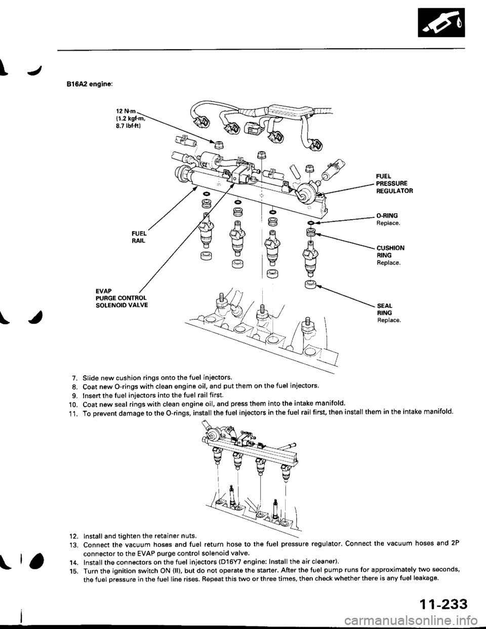
81642 engine:
EVAP
12 N.m
{1.2 kgl m;8.? lbt.ft)
FUELPRESSUREREGULATOR
O.RINGReplace.
cusHloNRINGReplace.
PURGE CONTROLSOLENOID VALVE
\
SEALRINGReplace.
7. Slide new cushion rings onto the fuel injectors.
8. Coat newO-ringswith clean engineoil, and putthem onthefuel injectors.
9. Insert the fuel injectors into the fuel rail first.
10. Coatnewseal rings with clean engine oil,and press them intothe intake manifold.
11. To prevent damage to the O-rings, installthe fuel injectors inthefuel rail first, then install them inthe intake manifold.
'12. Install and tighten the retainer nuts.
13. Connect the vacuum hoses and fuel return hose to the fuel pressure regulator, Connect the vacuum hoses and 2P
connector to the EVAP purge control solenoid valve.
14. Install the connectors on the fuel inl'ectors (D16YI engine; Install the air cleaner).
15. Turn the ignition switch ON (ll), butdo not operate the starter. After the tuel pump runs for approximately two seconds,
the fuel pressure in the fuel line rises. Repeat this two or three times, then check whether there is any fuel leakage.
11-233
Page 512 of 2189
Intake Air System
\JSystem DescriPtion
The system supp|ies air for a|| engine needs' |t consists of the intake air pipe' Air C|eaner (ACL}, intake air duct, Thrott|e
Body (TB), ldle Air control (lAc) valve and intake manifold. A resonator in the intake air pipe provides additional silencing
as air is drawn into the system.
D16Y5, D16Y8, 816A2 engine {M/Tl
YEL/ - From PGM-FIaLK - MA|N RELAY
BLK/BLU
-- ORN
INTAKEAIRDUCT
IROTARYIIAC VALVE
Iaru
ENGINECOOLANT
BLK/
INTAKEAIR DUCT
I
D16Y5 engine (CVT), D16Y8 engine (A/T)' f'ttlxr ,tla"tpoto
D16Y7 engine:
{ROTARY)IAC VALVE
VARIOUSSENSORS
INTAKEAIRPIPE
tr
RESONATOR
!r,
IAC VALVE
BLK
11-243
Page 515 of 2189

Intake Air System
Throttle Cable (cont'dl
4. Set the locknut on the cable bracket. Adjust theadjusting nut so that its free play is O mm.
5. Bemove the cable sheath from the throttle bracket,reset the adjusting nut and tighten the locknut.
O16Y5, D16Y8 engino:
ADJUSTING NUT
9.8 N.m{1.0 kgl.m,1.2 tbt.ttl
DtGYT 6ngine:
11-246
816A2 engine:
1. Open the throttle valve fully, then install the throttlecable in the throttle linkage. and install the cablehousing in the cable bracket,
THROTTLE LINK
LOCKNUTADJUSTINGNUT
Start the engine. Hold the engine at 3.000 rpm withno load (in Park or neutral) until the radiator fancomes on, then let it idle.
Hold the throttle link to the throttle lever; thereshould be no clearance.
Hold the cable sheath, removing all slack from thecable.
Turn the adjusting nut untit it is 3 mm {1/8 in.) awayfrom the cable bracket,
LOCKNUT9.8 N.m(1.0 kgt m,7.2 tM.ttl
ADJUSTING NUT
Tighten the locknut. The cable deflection shouldnow be 10 - 12 mm l3/B - 1/2 in.). lf nor. seeInspection/Adjustment.
3 mm 11/8 in.)
Page 517 of 2189
Intake Air System
J
Throttle Body (cont'dl
Removal
D16Y5, Dl6Y8, 81642 engine:
D15Y7 engine:
AIR CLEANER
{ACLI
22 N.m12.2 kgl.m,16 rbf.ftl
NOTE:
. Do not adjust the throttle stop screw.. After reassembly, adjust the throttle cable {see page l l-244).. The TP sensor is not removable.
IAT SENSOR
MAP SENSOR
GASKETReplace.
11-248
THROTTLE CABLE
Page 519 of 2189
Intake Air System
Fuel Injection Air (FlA) Controt System I'99 - 00 Dl6yg enginel
Dsscription
When the engine running lengine coolant below 149oF (6S"C)], the fuel Injection Air (FtA) Control Valve sends intake air tothe fuel iniectors.
E> : INTAKEAIR
FUELINJECTOB
11-250