Page 102 of 2189
Engine Removal/lnstallation
Removal(cont'dl
29. Remove the Ay'C compressor.
NOTE: Do not disconnect the Ay'C hoses.
30.
8x 1.25 mm A/C COMPRESSOR24 N.m (2.{ kgf.m, t7 tbtft}
Remove the shift cable (IVT).
NOTE:
. Take care not to bend the cable when removingit. Always replace any kinked cable with a newone.
. Adjust the shift cable when installing (see sec_tion 14).
8 x 1.25 mm22 N.m (2.2 kgf.m, 16 lbf.frl
LOCK WASHERBeplace.6x1.0mm14 N.m (1.4 kgf.m, tO tbtft)
5-8
A/C COMPRESSOR
t
{
31. Remove exhaust pipe A.
Dl6Y5. D16Y7 engines:
8 x 1.25 mm22 N.m 12.2 ksl.m. 16 tbI.fr)Replace.
SELF.LOCKING8 x 1.25 mm16 N.m (1.6 kgtm,12 tbt.ftlReplace.
D16Y8 ongin6;
8 x 1.25 mm22 N.m (2.2 kgf.m. 16 tbf.ftlReplace.
GASKETReplace.
SELF.LOCKING NUT10 x 1.25 mm33 N.m {3.4 kgt.m,25 lbr'frlReplace.
SELF.LOCKING NUT8 x 1.25 mm16 N.m 11.6 kgf.m, 12 lbtft)Replace.
SELF-LOCKING NUTl0 x 1.25 mm54 N.m (5.5 kgf.m, 40 lbf.ft)Replace.
Page 157 of 2189

Cylinder Head
Installation (cont'dl
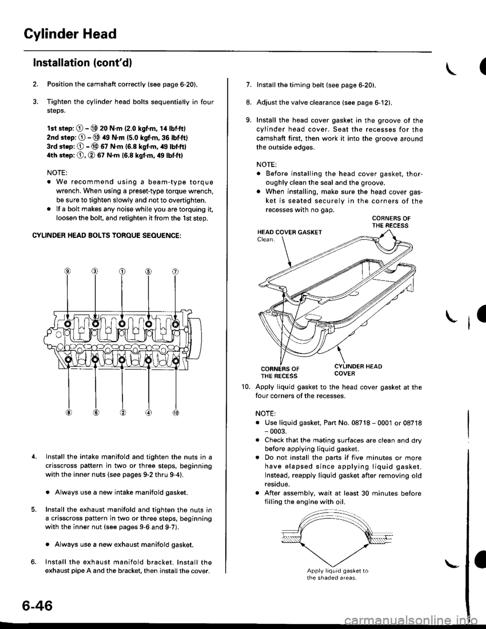
Position the camshaft correctly (see page 6-20).
Tighten the cylinder head bolts sequentially in four
steps.
rsr st.p: O - @ 20 N.m (2.0 kgf.m, 14 lbf'ft|
2nd srep: O - @ 49 N.m (5.0 kgf.m, 36 tbtft)
3rd stop; O - @ 67 N.m {6.8 kgf.m, /r9 lbl'ft}
4th st6p: O, O 67 N.m 16.8 kgf.m, 49 tbf.ftl
NOTE:
. We recommend using a beam-type torque
wrench, When using a preset-type torque wrench.
be sure to tighten slowly and not to overtighten.
. If a bolt makesany noisewhileyou aretorquing it,
loosen the bolt, and retighten it from the 1st step,
CYLINDER HEAD BOLTS TOROUE SEOUENCE:
Install the intake manifold and tighten the nuts in a
crisscross pattern in two or three steps, beginning
with the inner nuts (see pages 9-2 thru 9-4).
. Always use a new intake manifold gasket.
Install the exhaust manifold and tighten the nuts in
a crisscross pattern in two or three steps, beginning
with the inner nut {see pages 9-6 and g-7).
. Always use a new exhaust manifold gasket.
Install the exhaust manifold bracket. lnstall the
exhaust pipe A and the bracket, then install the cover.
4.
6-46
\-
(
7.Installthe timing belt (see page 6-20).
Adjust the valve clearance (see page el2),
Install the head cover gasket in the groove of the
cylinder head cover, Seat the recesses for the
camshaft first, then work it into the groove around
the outside edges.
NOTE:
. Before installing the head cover gasket, thor-
oughly clean the seal and the groove.
. When installing, make sure the head cover gas-
ket is seated securely in the corners of the
recesses wath no gap.
COBNERS OFTHE RECESS
CORNERS OFTHE REcEss covEB
Apply liquid gasket to the head cover gasket at the
four corners of the recesses.
NOTE:
. Use liquid gasket, Pan No. 08718 - 0001 or 08718- 0003.
. Check that the mating surfaces are clean and dry
before applying liquid gasket.
. Do not install the parts if five minutes or more
have elapsed since applying liquid gasket.
Instead, reapply liquid gasket after removing old
residue.
. After assembly, wait at least 30 minutes before
filling the engine with oil.
8.
9.
I
10.
Page 234 of 2189
Oil Filter
Replacement
After the engine has been run, the exhaust pipe willbe hot; be careful when working around ihe exhaustpipe.
Be careful when loosening the drain bolt whils theengine is hot. Burns can resuh because the oil tem-peratu16 is very high.
Remove the oil filter with the oil filter wrencn.
Inspect the threads and rubber seal on the new filter.Wipe off the seat on the engine block, then apply alight coat of oil to the new filter,s rubber seal.
NOTE: Use onty fitters with a built-in bypass sys,tem.
Apply oil to rubber sealbefore installing.
l.
Inspect threads andrubber seal surface.
8-8
Install the oil filter by hand.
After the rubber seal seats, tighten the oil filter clock_wise with the oil filter wrench.
Tighten: 7/8 tu.n clockwise.
Tightening tolque: 22 N.m (2.2 kgt.m, 16lbf.ft)
OIL FILTER WRENCH07912 - 6110001
Page 242 of 2189
lntake Manifold/Exhaust System
lntake Manifold
Replacement ....................................... 9-2
Exhaust Manifold
Rep|acement ....................................". 9-6
Exhaust Pipe and Muffler
Replacement ...............................'.'.".. 9-9
Three Way Catalytic Converter {TWCI
Inspection .................."'. 9-12
Heated Oxygen Sensor (HO2SI
Rep|acement ...........................'.."....." 9-12
L_s
r f o
Page 250 of 2189
Exhaust Pipe and Muffler
\
Replacement
NOTE: Use new gaskets and self-locking nuts when reassembling
D16Y5, D16Y7 engines:
HEAT SHIELO
6x1.0mm9.8 N.m tl.0 kgf'm,7.2lbf'ft)
EXHAUST PIPE B
EXHAUST PIPE TIP
/
O
6x1.0mm9.8 N.m 11.0 kgt m, 7.2 lbf'ftl
oP----------------8 x 1.25 mm22 N.m 12.2 kg .m,
16 tbf.f Replace.Tighlen the bolts insteps, alternatingside to-side.
8 x 1.25 mm22 N.m 12.2 kgl'm, 16lbl'ttl
Replace.Tighten the bolts in steps,
alternating side-to-side
GASKETReplace.
SELF-LOCKING NUT
8 x 1.25 mm16 N.m 11.6 kgt m, 12 lbt'ftl
Replace.
(cont'd)
9-9
MUFFLER
neOlace. ----------"+@
SELF.LOCKING NUT10 x 1.25 mm33 N.m (3.4 ksd.m,25 lbf.frlReplace.
Page 251 of 2189
Exhaust Pipe and Muffler
Replacement {cont'dl
NOTE: Use new gaskets and self-locking nuts when reassembling.
D16Y8 engine:
MUFFLER
HEAT SHIELD
6x1.0mm9.8 N.m (1.0 kgl m, 7.2 lbf.ft)
EXHAUST PIPE
SECONDARY HO2544 N.m {4.5 kgl.m, 33 lbtftlReplacement, page 9-10
GASKETSReplace.
EXHAUST PIPE A
SELF-LOCKING NUT10 x 1.25 mm54 N.m {5.5 kgl.m, 40 lbtft}Replace.16 N.m {1.6 kgl.m, 12lbf.ft}Replace-
d'*'ou"'"'""'
6x1.0mm9.8 N.m (1.0 ksf m,7.2lbf ft)
8 x 1.25 mm22 N.rn 12.2 kgl.m,16 tbt.ft)Replace.Tighten the bolts insteps, alternatrngside-to-side.
SELF.LOCKING NUT10 x 1.25 mm33 N.m {3.4 kgf.m,25 tbtftlReplace.
TWCinspection, page 9-12
I x 1-25 mm22 N m (2.2 kgf.m. 16 lbfft)
Tighten the bolts in steps,alternating side'to sade.e)GASKETHeplace.
9-10
Page 252 of 2189
816A2 engino:
MUFFLER_.,. EXHAUST PIPE
-/- tlP
g
\6r1.omm
9.8 N m 11.0 kgf'm, 7.2 lbl'ttl
GASKETReplace.
8 x 1.25 mm2. N'm 12.2 kgl-m,t6 tbtf0Replace.Tighten the bolts insteps, alternatrngside-to-side.6x1,0mm9,8 N.m 11.07.2lbl4rl
SELF-LOCKING NUTl0 x 1.25 mm
3:t N.m {3.4 kgf m,24lbf'ftl
ReDlace.PRIMARY IIEATEDOXYGEN SENSOR{PRIMARY HO2S)ll N.m (4.5 kgl.m,33 tbt f0Replacement,
SECONDARY HEATEDOXYGEN SENSOR{SECONDARY HO2SIlrt N.m 14.5 kgf.m,33 rbl.ft)Replacement, page 9-13
GASKETR€place.
twcInspection, page 9-12GASKEISReplace.
SELF.L(rcKNG NUT10 x 1.25 mm5,r N.m 15.5 kgf.m, ,|{} lbf.ft)ReDlace.
8x1.25mm22 N.m {2.2 kgt m, 16 lbf.ftlReplsce.Tight6n the bolts in st6ps,alternating side-to-side.8 x 1.25 mm16 N.m 11.6 kgt.m,12 rbf.ft)F€pl8ce.
I
Replaca.
9-11
Page 410 of 2189

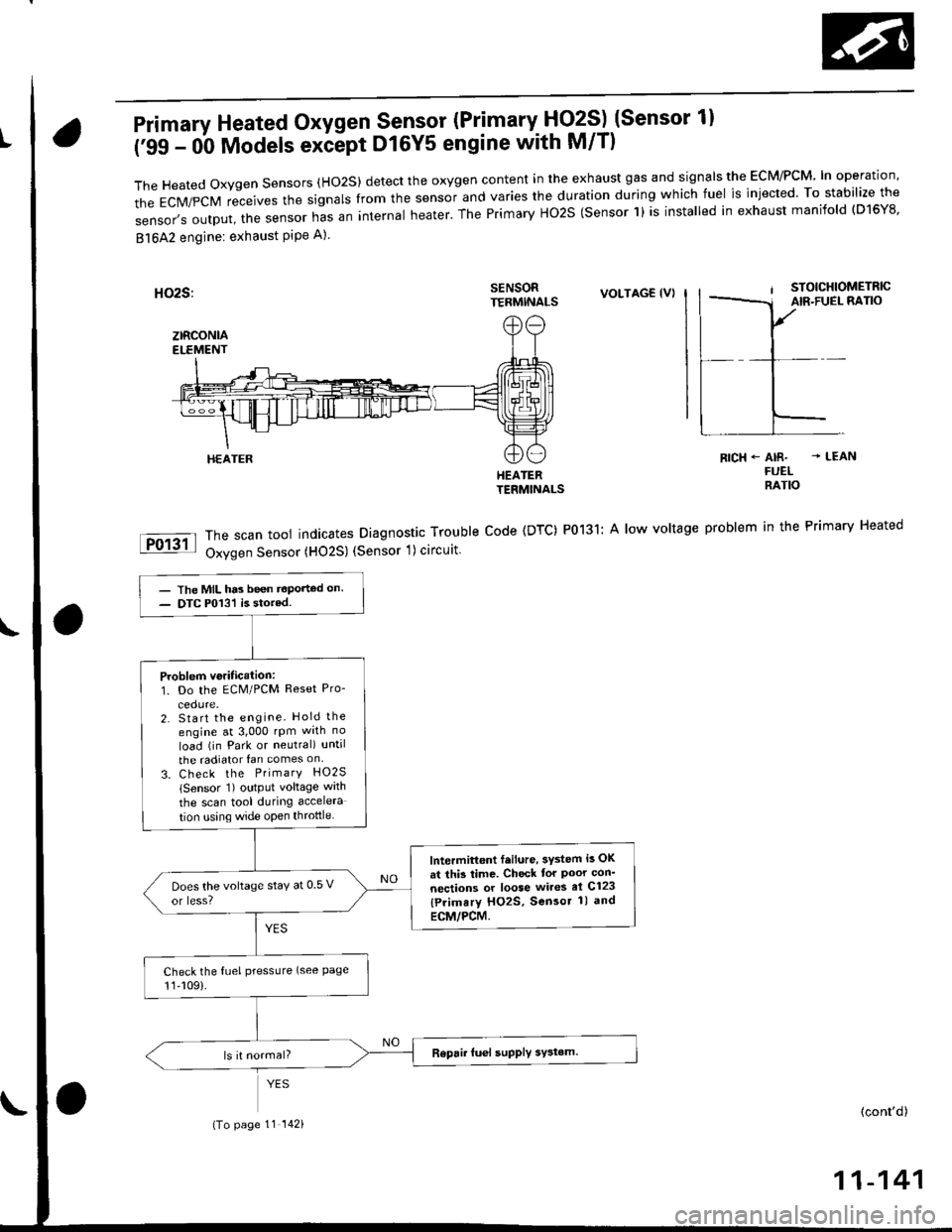
Primary Heated Oxygen Sensor (Primary- Fjq?S) (Sensor 1l
('99 - 0b Models exiept D16Y5 engine with M/T)
TheHeatedoxygensensors(Ho2S)detecttheoxygencontentintheexhaustgasandsigna|stheEcM/PcM'|noperation,
the EcM/pcM receives the signars from the sensor and varies the duration during which fuel is injected. To stabilize the
sensor,soutput,thesensornasaninternaIheater.ThePrimaryHo2S(sensorl)isinsta|ledinexhaustmanifo|d(D16Y8.
81642 engine: exhaust PiPe A)
SENSORTERMINALSVOLTAG€ (VI
HEATERTERMINALS
The scan tool indicates Diagnostic Trouble Code (DTC) P0131: A low voltage
Oxygen Sensor (HO2S) (Sensor 1) circuit
RICH+ AIR- - LEANFUELRATIO
problem in the Primary Heated
HEATER
- The MIL has been t€Ported on.- DTC P013'l is stored.
Problem veritication:1. Do the ECM/PCM Reset Pro-
2. Start the engine. Hold the
engine at 3,000 rpm wrth no
load (in Park or neutral) until
the radiator fan comes on
3. Check the PrimarY HO2S
lSensor 1) output voltage wath
the scan tool during accelera
tion using wide open throttle
lntermittont f.ilure, 3ystem i3 OK
at thi3 time. Check tor Poor con'
nections or loose wires el C123
{Primary HO2S, Sensor 1) and
ECM/PCM.
Does the voltage stay at 0 5 v
or less?
Check the fuel pressLlre (see Page11,109).
(To page 11 142)(cont'd)
11-141