1999 FORD F250 SUPER DUTY spare tire
[x] Cancel search: spare tirePage 152 of 248
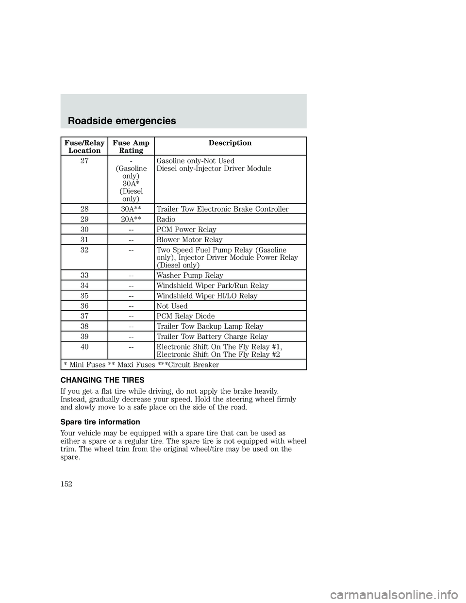
Fuse/Relay
LocationFuse Amp
RatingDescription
27 -
(Gasoline
only)
30A*
(Diesel
only)Gasoline only-Not Used
Diesel only-Injector Driver Module
28 30A** Trailer Tow Electronic Brake Controller
29 20A** Radio
30 -- PCM Power Relay
31 -- Blower Motor Relay
32 -- Two Speed Fuel Pump Relay (Gasoline
only), Injector Driver Module Power Relay
(Diesel only)
33 -- Washer Pump Relay
34 -- Windshield Wiper Park/Run Relay
35 -- Windshield Wiper HI/LO Relay
36 -- Not Used
37 -- PCM Relay Diode
38 -- Trailer Tow Backup Lamp Relay
39 -- Trailer Tow Battery Charge Relay
40 -- Electronic Shift On The Fly Relay #1,
Electronic Shift On The Fly Relay #2
* Mini Fuses ** Maxi Fuses ***Circuit Breaker
CHANGING THE TIRES
If you get a flat tire while driving, do not apply the brake heavily.
Instead, gradually decrease your speed. Hold the steering wheel firmly
and slowly move to a safe place on the side of the road.
Spare tire information
Your vehicle may be equipped with a spare tire that can be used as
either a spare or a regular tire. The spare tire is not equipped with wheel
trim. The wheel trim from the original wheel/tire may be used on the
spare.
Roadside emergencies
152
Page 153 of 248
If your vehicle is equipped with 4WD, a spare tire of a different
size than the road tires should not be used. Such a tire could
result in damage to driveline components and make the vehicle
difficult to control.
Location of the spare tire and tools
The spare tire and tools for your vehicle are stowed in the following
locations:
Tool Location
Spare tire (pick-up
trucks only)Under the vehicle, just forward of the rear
bumper
Jack Regular cab, crew cab and SuperCab without
rear bench seat: Fastened to floor pan behind
rearmost seat on passenger side
SuperCab with rear bench seat: Under rear
bench on passenger side
Jack handle and lug
wrenchOn top of the radiator support at the front of
the engine compartment
Removing the spare tire (with spare tire carrier only)
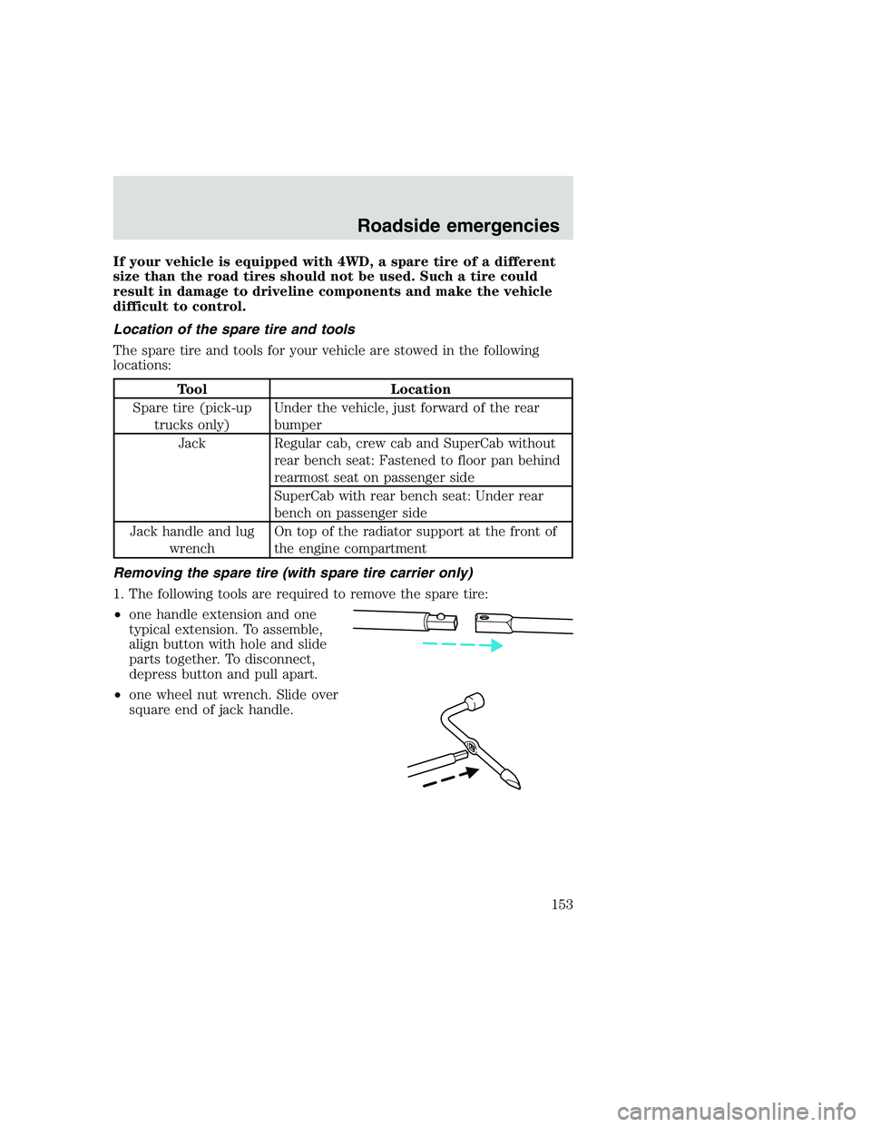
1. The following tools are required to remove the spare tire:
•one handle extension and one
typical extension. To assemble,
align button with hole and slide
parts together. To disconnect,
depress button and pull apart.
•one wheel nut wrench. Slide over
square end of jack handle.
Roadside emergencies
153
Page 154 of 248
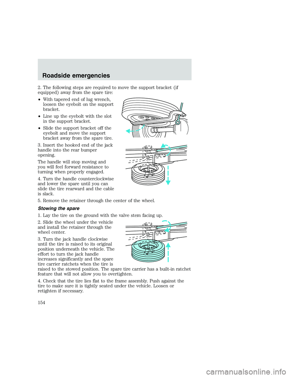
2. The following steps are required to move the support bracket (if
equipped) away from the spare tire:
•With tapered end of lug wrench,
loosen the eyebolt on the support
bracket.
•Line up the eyebolt with the slot
in the support bracket.
•Slide the support bracket off the
eyebolt and move the support
bracket away from the spare tire.
3. Insert the hooked end of the jack
handle into the rear bumper
opening.
The handle will stop moving and
you will feel forward resistance to
turning when properly engaged.
4. Turn the handle counterclockwise
and lower the spare until you can
slide the tire rearward and the cable
is slack.
5. Remove the retainer through the center of the wheel.
Stowing the spare
1. Lay the tire on the ground with the valve stem facing up.
2. Slide the wheel under the vehicle
and install the retainer through the
wheel center.
3. Turn the jack handle clockwise
until the tire is raised to its original
position underneath the vehicle. The
effort to turn the jack handle
increases significantly and the spare
tire carrier ratchets when the tire is
raised to the stowed position. The spare tire carrier has a built-in ratchet
feature that will not allow you to overtighten.
4. Check that the tire lies flat to the frame assembly. Push against the
tire to make sure it is tightly seated under the vehicle. Loosen or
retighten if necessary.
Roadside emergencies
154
Page 155 of 248
5. The following steps are required to secure the support bracket (if
equipped) under the spare tire:
•Move the support bracket over the spare tire.
•Slide the support bracket over the eyebolt into the slot on the support
bracket.
•Tighten the eyebolt with tapered end of lug wrench leaving it
positioned at a right angle of the slot on the support bracket.
Tire change procedure
1. Park on a level surface, activate
hazard flashers and set the parking
brake.
•Automatic transmission: Place
gearshift lever in P (Park).
•Manual transmission: Place
gearshift lever in R (Reverse).
•Electronic Shift On the Fly four
wheel drive: Place transfer case
in 2WD, 4x4 HIGH or 4x4 LOW.
•Manual shift transfer case four
wheel drive: Place transfer case
in 2H, 4H or 4L.
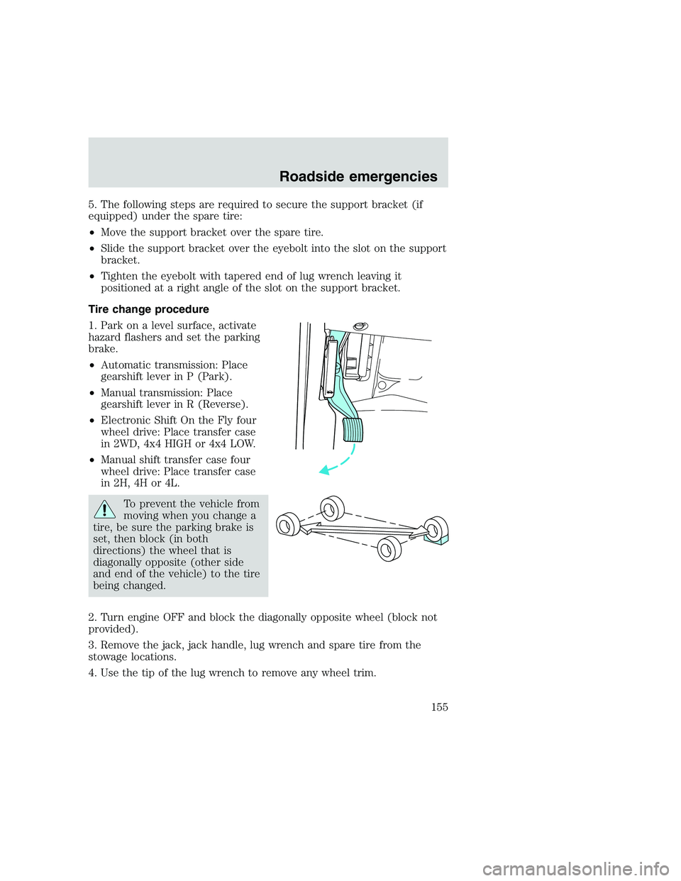
To prevent the vehicle from
moving when you change a
tire, be sure the parking brake is
set, then block (in both
directions) the wheel that is
diagonally opposite (other side
and end of the vehicle) to the tire
being changed.
2. Turn engine OFF and block the diagonally opposite wheel (block not
provided).
3. Remove the jack, jack handle, lug wrench and spare tire from the
stowage locations.
4. Use the tip of the lug wrench to remove any wheel trim.
Roadside emergencies
155
Page 159 of 248
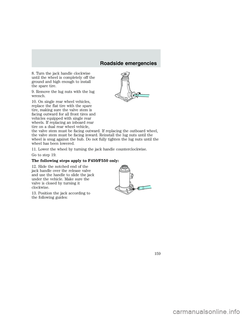
8. Turn the jack handle clockwise
until the wheel is completely off the
ground and high enough to install
the spare tire.
9. Remove the lug nuts with the lug
wrench.
10. On single rear wheel vehicles,
replace the flat tire with the spare
tire, making sure the valve stem is
facing outward for all front tires and
vehicles equipped with single rear
wheels. If replacing an inboard rear
tire on a dual rear wheel vehicle,
the valve stem must be facing outward. If replacing the outboard wheel,
the valve stem must be facing inward. Reinstall the lug nuts until the
wheel is snug against the hub. Do not fully tighten the lug nuts until the
wheel has been lowered.
11. Lower the wheel by turning the jack handle counterclockwise.
Go to step 19.
The following steps apply to F450/F550 only:
12. Slide the notched end of the
jack handle over the release valve
and use the handle to slide the jack
under the vehicle. Make sure the
valve is closed by turning it
clockwise.
13. Position the jack according to
the following guides:
Roadside emergencies
159
Page 161 of 248
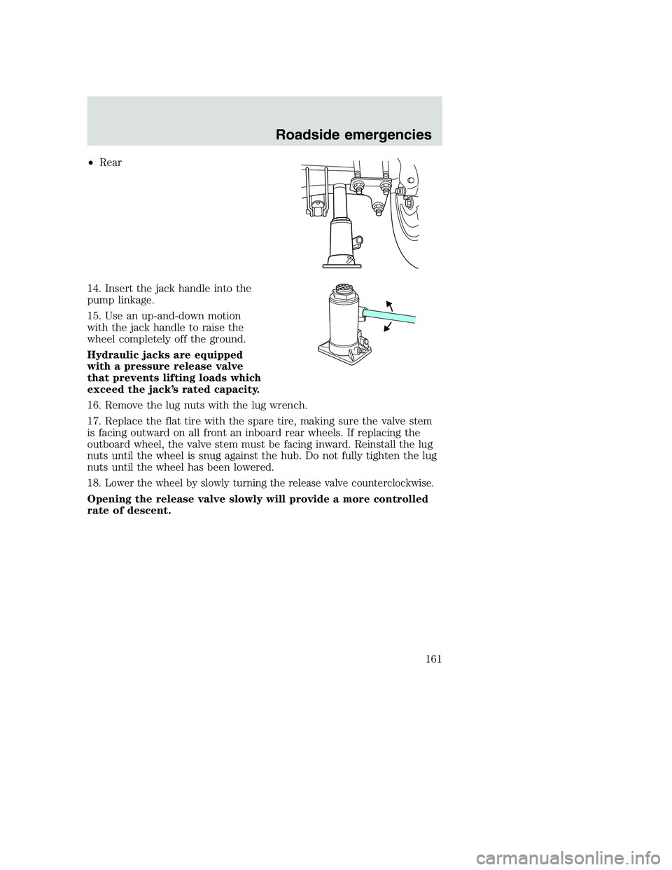
•Rear
14. Insert the jack handle into the
pump linkage.
15. Use an up-and-down motion
with the jack handle to raise the
wheel completely off the ground.
Hydraulic jacks are equipped
with a pressure release valve
that prevents lifting loads which
exceed the jack’s rated capacity.
16. Remove the lug nuts with the lug wrench.
17. Replace the flat tire with the spare tire, making sure the valve stem
is facing outward on all front an inboard rear wheels. If replacing the
outboard wheel, the valve stem must be facing inward. Reinstall the lug
nuts until the wheel is snug against the hub. Do not fully tighten the lug
nuts until the wheel has been lowered.
18.
Lower the wheel by slowly turning the release valve counterclockwise.
Opening the release valve slowly will provide a more controlled
rate of descent.
Roadside emergencies
161
Page 162 of 248
The following steps apply to all vehicles:
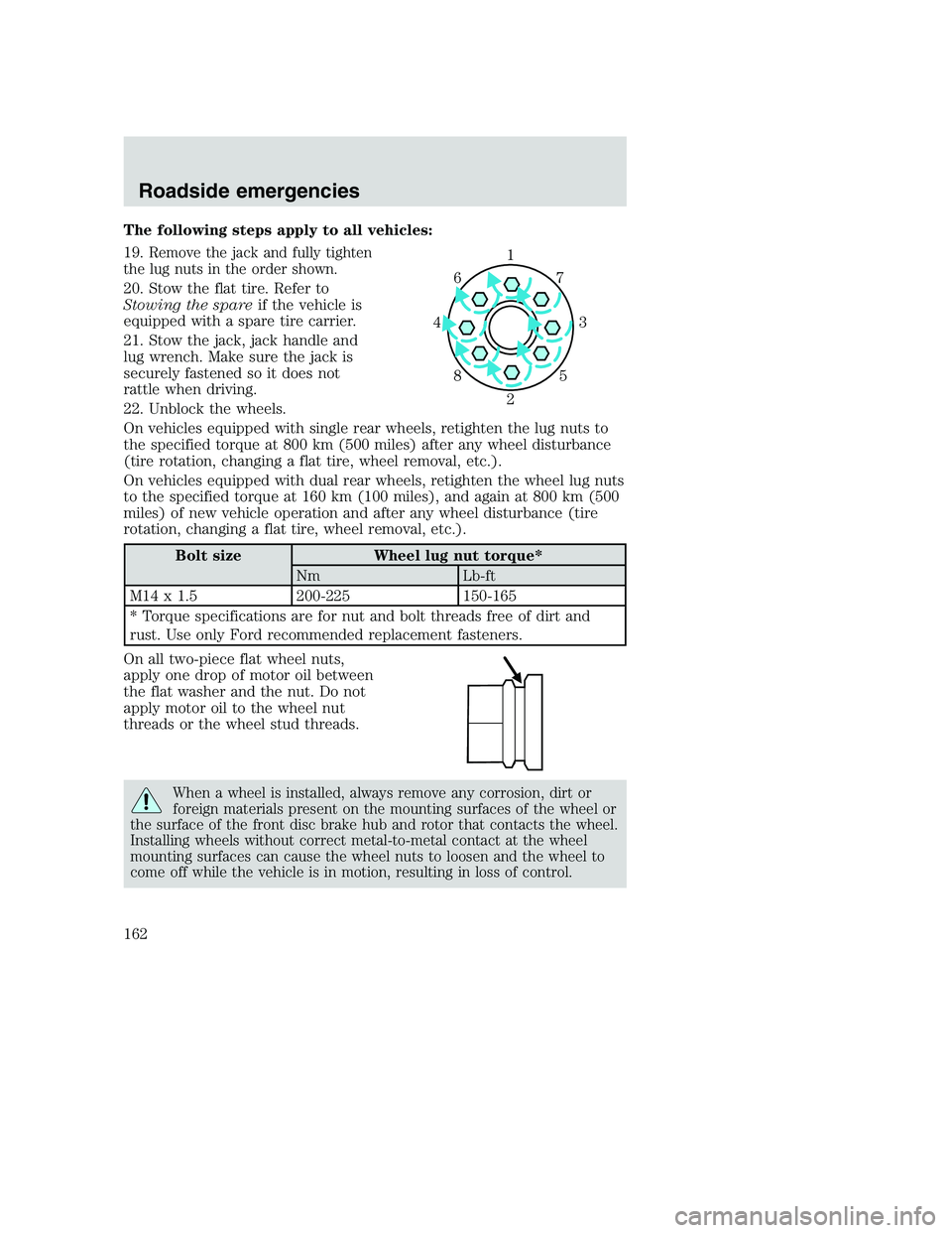
19.
Remove the jack and fully tighten
the lug nuts in the order shown.
20. Stow the flat tire. Refer to
Stowing the spareif the vehicle is
equipped with a spare tire carrier.
21. Stow the jack, jack handle and
lug wrench. Make sure the jack is
securely fastened so it does not
rattle when driving.
22. Unblock the wheels.
On vehicles equipped with single rear wheels, retighten the lug nuts to
the specified torque at 800 km (500 miles) after any wheel disturbance
(tire rotation, changing a flat tire, wheel removal, etc.).
On vehicles equipped with dual rear wheels, retighten the wheel lug nuts
to the specified torque at 160 km (100 miles), and again at 800 km (500
miles) of new vehicle operation and after any wheel disturbance (tire
rotation, changing a flat tire, wheel removal, etc.).
Bolt size Wheel lug nut torque*
Nm Lb-ft
M14 x 1.5 200-225 150-165
* Torque specifications are for nut and bolt threads free of dirt and
rust. Use only Ford recommended replacement fasteners.
On all two-piece flat wheel nuts,
apply one drop of motor oil between
the flat washer and the nut. Do not
apply motor oil to the wheel nut
threads or the wheel stud threads.
When a wheel is installed, always remove any corrosion, dirt or
foreign materials present on the mounting surfaces of the wheel or
the surface of the front disc brake hub and rotor that contacts the wheel.
Installing wheels without correct metal-to-metal contact at the wheel
mounting surfaces can cause the wheel nuts to loosen and the wheel to
come off while the vehicle is in motion, resulting in loss of control.
1
3 4
27 6
5 8
Roadside emergencies
162
Page 190 of 248
INFORMATION ABOUT TIRE QUALITY GRADES
New vehicles are fitted with tires
that have their Tire Quality Grade
(described below) molded into the
tire’s sidewall. These Tire Quality
Grades are determined by standards
that the United States Department
of Transportation has set.
Tire Quality Grades apply to new
pneumatic tires for use on
passenger cars. They do not apply
to deep tread, winter-type snow
tires, space-saver or temporary use spare tires, tires with nominal rim
diameters of 10 to 12 inches or limited production tires as defined in
Title 49 Code of Federal Regulations Part 575.104(c)(2).
U.S. Department of Transportation-Tire quality grades:The U.S.
Department of Transportation requires Ford to give you the following
information about tire grades exactly as the government has written it.
Treadwear
The treadwear grade is a comparative rating based on the wear rate of
the tire when tested under controlled conditions on a specified
government test course. For example, a tire graded 150 would wear one
and one-half (1 1/2) times as well on the government course as a tire
graded 100. The relative performance of tires depends upon the actual
conditions of their use, however, and may depart significantly from the
norm due to variations in driving habits, service practices, and
differences in road characteristics and climate.
Traction AA A B C
The traction grades, from highest to lowest are AA, A, B, and C. Those
grades represent the tire’s ability to stop on wet pavement as measured
under controlled conditions on specified government test surfaces of
asphalt and concrete. A tire marked C may have poor traction
performance.
The traction grade assigned to this tire is based on
straight-ahead braking traction tests, and does not include
acceleration, cornering, hydroplaning or peak traction characteristics.
Maintenance and care
190