Page 96 of 232

Steps you can take to properly position yourself away from the airbag:
²Move your seat to the rear as far as you can while still reaching the
pedals comfortably.
²
Recline the seat slightly (one or two degrees) from the upright position.
Do not put anything on or over the air bag module. Placing
objects on or over the air bag inflation area may cause those
objects to be propelled by the air bag into your face and torso causing
serious injury.
Do not attempt to service, repair, or modify the Air Bag
Supplemental Restraint System or its fuses. See your Ford or
Lincoln-Mercury dealer.
Children and air bags
For additional important safety information, read all information on
safety restraints in this guide.
Children must always be properly restrained. Failure to follow these
instructions may increase the risk of injury in a collision.
An infant in a rear-facing seat faces a high risk of serious or fatal
injuries from a deploying passenger air bag. Rear facing infant
seats should NEVER be placed in the front seats, unless the passenger
air bag is turned off. SeePassenger air bag ON/OFF switch.
How does the air bag supplemental restraint system work?
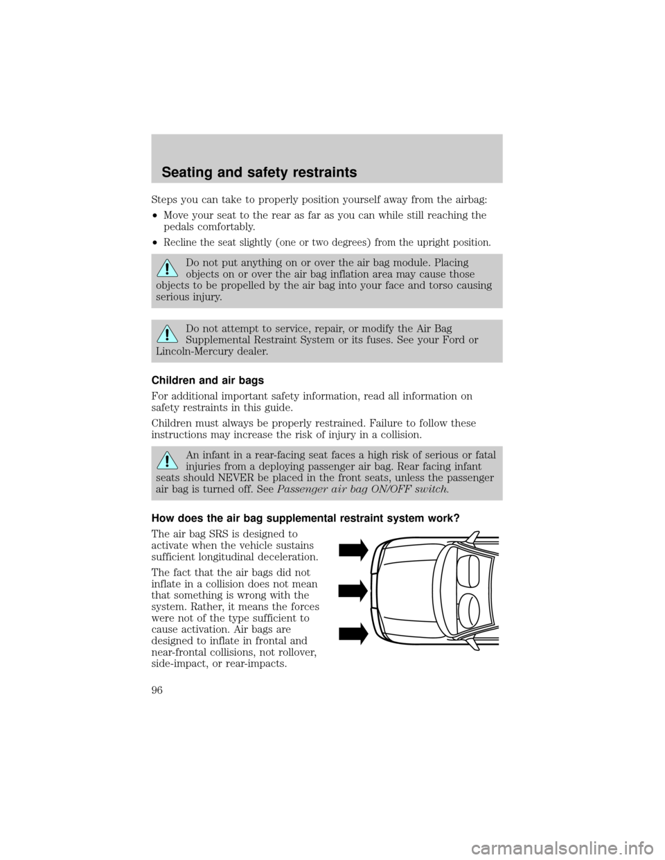
The air bag SRS is designed to
activate when the vehicle sustains
sufficient longitudinal deceleration.
The fact that the air bags did not
inflate in a collision does not mean
that something is wrong with the
system. Rather, it means the forces
were not of the type sufficient to
cause activation. Air bags are
designed to inflate in frontal and
near-frontal collisions, not rollover,
side-impact, or rear-impacts.
Seating and safety restraints
96
Page 120 of 232

again. If the warning light reappears, turn the air suspension switch off
and have the vehicle serviced by a dealer or qualified service technician.
If the vehicle is loaded beyond the recommended maximum payload, the
CK SUSP light may illuminate. To correct this condition, remove or
redistribute the payload according to the recommended requirements
and follow the procedure outlined above.
AUTOMATIC TRANSMISSION OPERATION (IF EQUIPPED)
Brake-shift interlock
This vehicle is equipped with a brake-shift interlock feature that prevents
the gearshift from being moved from P (Park) unless the brake pedal is
depressed.
If you cannot move the gearshift out of P (Park) with the brake pedal
depressed:
1. Apply the parking brake, turn ignition key to LOCK, then remove the
key.
2. Insert the key and turn it to OFF. Apply the brake pedal and shift to N
(Neutral).
3. Start the vehicle.
If it is necessary to use the above procedure to move the gearshift, it is
possible that a fuse has blown or the vehicle's brakelamps are not
operating properly. Refer toFuses and relaysin theRoadside
emergencieschapter.
Do not drive your vehicle until you verify that the brakelamps
are working.
If your vehicle gets stuck in mud or snow it may be rocked out by
shifting from forward and reverse gears, stopping between shifts, in a
steady pattern. Press lightly on the accelerator in each gear.
Do not rock the vehicle for more than a few minutes. The
transmission and tires may be damaged or the engine may
overheat.
Always set the parking brake fully and make sure the gearshift is
latched in P (Park). Turn off the ignition whenever you leave
your vehicle.
Driving
120
Page 147 of 232

Snowplowing with your air bag equipped vehicle
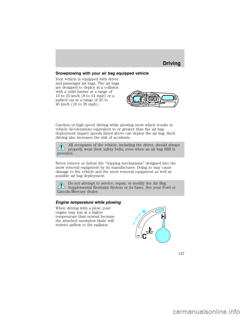
Your vehicle is equipped with driver
and passenger air bags. The air bags
are designed to deploy in a collision
with a solid barrier at a range of
13 to 23 km/h (8 to 14 mph) or a
parked car at a range of 25 to
45 km/h (16 to 28 mph).
Careless or high speed driving while plowing snow which results in
vehicle decelerations equivalent to or greater than the air bag
deployment impact speeds listed above can deploy the air bag. Such
driving also increases the risk of accidents.
All occupants of the vehicle, including the driver, should always
properly wear their safety belts, even when an air bag SRS is
provided.
Never remove or defeat the ªtripping mechanismsº designed into the
snow removal equipment by its manufacturer. Doing so may cause
damage to the vehicle and the snow removal equipment as well as
possible air bag deployment.
Do not attempt to service, repair, or modify the Air Bag
Supplemental Restraint System or its fuses. See your Ford or
Lincoln-Mercury dealer.
Engine temperature while plowing
When driving with a plow, your
engine may run at a higher
temperature than normal because
the attached snowplow blade will
restrict airflow to the radiator.
H
C
Driving
147
Page 150 of 232
The fuel pump shut-off switch is
located in the passenger's foot well,
behind the kick panel.
FUSES AND RELAYS
Fuses
If electrical components in the
vehicle are not working, a fuse may
have blown. Blown fuses are
identified by a broken wire within
the fuse. Check the appropriate
fuses before replacing any electrical
components.
Always replace a fuse with one that has the specified amperage
rating. Using a fuse with a higher amperage rating can cause
severe wire damage and could start a fire.
15
Roadside emergencies
150
Page 151 of 232
Standard fuse amperage rating and color
COLOR
Fuse
RatingMini
FusesStandard
FusesMaxi
FusesCartridge
Maxi
FusesFuse Link
Cartridge
2A Grey Grey Ð Ð Ð
3A Violet Violet Ð Ð Ð
4A Pink Pink Ð Ð Ð
5A Tan Tan Ð Ð Ð
7.5A Brown Brown Ð Ð Ð
10A Red Red Ð Ð Ð
15A Blue Blue Ð Ð Ð
20A Yellow Yellow Yellow Blue Blue
25A Natural Natural Ð Ð Ð
30A Green Green Green Pink Pink
40A Ð Ð Orange Green Green
50A Ð Ð Red Red Red
60A Ð Ð Blue Ð Yellow
70A Ð Ð Tan Ð Brown
80A Ð Ð Natural Ð Black
Passenger compartment fuse panel
The fuse panel is located below and to the left of the steering wheel by
the brake pedal. Remove the panel cover to access the fuses.
To remove a fuse use the fuse puller tool provided on the fuse panel
cover.
Roadside emergencies
151
Page 152 of 232
The fuses are coded as follows.
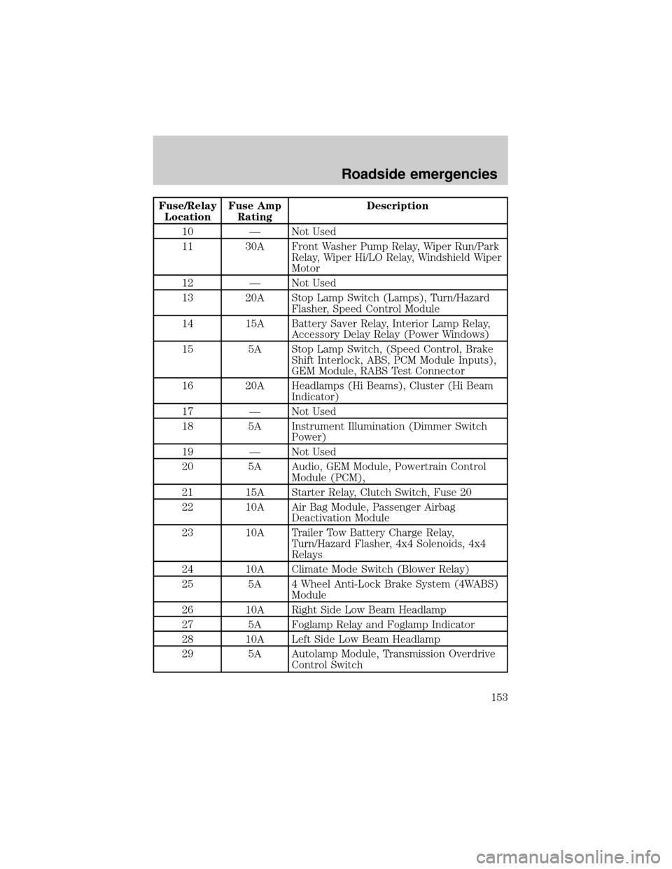
Fuse/Relay
LocationFuse Amp
RatingDescription
1 15A Audio
2 5A Powertrain Control Module (PCM), Cluster
3 20A Cigar Lighter, OBD-II Scan Tool Connector
4 15A Autolamp Module, Remote Entry Module,
Mirrors
5 15A AC Clutch Relay, Speed Control Module,
Reverse Lamp, Climate Mode Switch,
Daytime Running Lamp Relay
6 5A Cluster, Brake Shift Interlock Solenoid,
Rear Air Suspension Module, GEM Module
7 Ð Not Used
8 5A Radio, Remote Entry Module, GEM Module
9 Ð Not Used
FUSE1 12 22
21323
617 27
718 28
819 29
930
20
31 21 11 10
RELAY
5 RELAY
4 RELAY
3 RELAY
2 RELAY
1
31424
41525
51626
Roadside emergencies
152
Page 153 of 232

Fuse/Relay
LocationFuse Amp
RatingDescription
10 Ð Not Used
11 30A Front Washer Pump Relay, Wiper Run/Park
Relay, Wiper Hi/LO Relay, Windshield Wiper
Motor
12 Ð Not Used
13 20A Stop Lamp Switch (Lamps), Turn/Hazard
Flasher, Speed Control Module
14 15A Battery Saver Relay, Interior Lamp Relay,
Accessory Delay Relay (Power Windows)
15 5A Stop Lamp Switch, (Speed Control, Brake
Shift Interlock, ABS, PCM Module Inputs),
GEM Module, RABS Test Connector
16 20A Headlamps (Hi Beams), Cluster (Hi Beam
Indicator)
17 Ð Not Used
18 5A Instrument Illumination (Dimmer Switch
Power)
19 Ð Not Used
20 5A Audio, GEM Module, Powertrain Control
Module (PCM),
21 15A Starter Relay, Clutch Switch, Fuse 20
22 10A Air Bag Module, Passenger Airbag
Deactivation Module
23 10A Trailer Tow Battery Charge Relay,
Turn/Hazard Flasher, 4x4 Solenoids, 4x4
Relays
24 10A Climate Mode Switch (Blower Relay)
25 5A 4 Wheel Anti-Lock Brake System (4WABS)
Module
26 10A Right Side Low Beam Headlamp
27 5A Foglamp Relay and Foglamp Indicator
28 10A Left Side Low Beam Headlamp
29 5A Autolamp Module, Transmission Overdrive
Control Switch
Roadside emergencies
153
Page 154 of 232

Fuse/Relay
LocationFuse Amp
RatingDescription
30 30A Passive Anti Theft Transceiver, Cluster,
Ignition Coils, Powertrain Control Module
Relay
31 Ð Not Used
Relay 1 Ð Interior Lamp Relay
Relay 2 Ð Battery Saver Relay
Relay 4 Ð One Touch Down Window Relay
Relay 5 Ð ACC Delay Relay
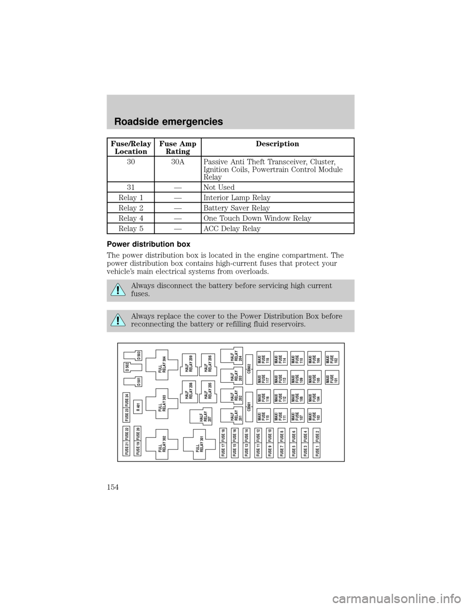
Power distribution box
The power distribution box is located in the engine compartment. The
power distribution box contains high-current fuses that protect your
vehicle's main electrical systems from overloads.
Always disconnect the battery before servicing high current
fuses.
Always replace the cover to the Power Distribution Box before
reconnecting the battery or refilling fluid reservoirs.
MAXI
FUSE
115MAXI
FUSE
116MAXI
FUSE
117
MAXI
FUSE
118
MAXI
FUSE
111MAXI
FUSE
112MAXI
FUSE
113
MAXI
FUSE
114
MAXI
FUSE
107MAXI
FUSE
108MAXI
FUSE
109
MAXI
FUSE
110
MAXI
FUSE
103MAXI
FUSE
104MAXI
FUSE
105
MAXI
FUSE
106
MAXI
FUSE
101MAXI
FUSE
102 CB601 CB602 FUSE 17 FUSE 18FUSE 21 FUSE 22
FUSE 19 FUSE 20FUSE 23
FULL
RELAY 302R 401
D 501 FUSE 24
FUSE 15 FUSE 16
FUSE 13 FUSE 14
FUSE 11 FUSE 12
FUSE 9 FUSE 10
FUSE 7 FUSE 8
FUSE 5 FUSE 6
FUSE 3 FUSE 4
FUSE 1 FUSE 2
D 503 D 502
FULL
RELAY 301HALF
RELAY
207
FULL
RELAY 303
FULL
RELAY 304
HALF
RELAY
201
HALF
RELAY
202HALF
RELAY 208
HALF
RELAY 209
HALF
RELAY 205
HALF
RELAY 206
HALF
RELAY
203
HALF
RELAY
204
Roadside emergencies
154