Page 26 of 96

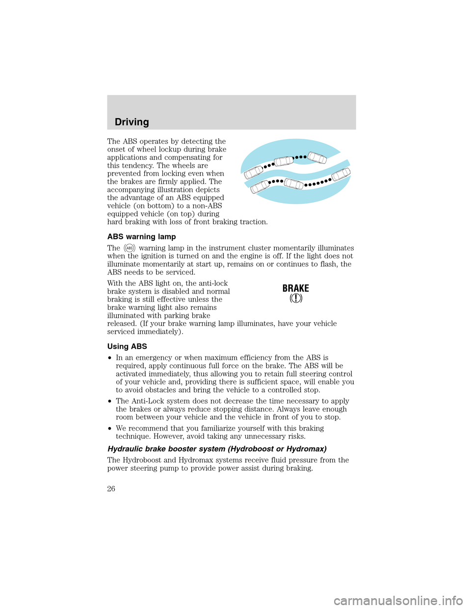
The ABS operates by detecting the
onset of wheel lockup during brake
applications and compensating for
this tendency. The wheels are
prevented from locking even when
the brakes are firmly applied. The
accompanying illustration depicts
the advantage of an ABS equipped
vehicle (on bottom) to a non-ABS
equipped vehicle (on top) during
hard braking with loss of front braking traction.
ABS warning lamp
The
ABSwarning lamp in the instrument cluster momentarily illuminates
when the ignition is turned on and the engine is off. If the light does not
illuminate momentarily at start up, remains on or continues to flash, the
ABS needs to be serviced.
With the ABS light on, the anti-lock
brake system is disabled and normal
braking is still effective unless the
brake warning light also remains
illuminated with parking brake
released. (If your brake warning lamp illuminates, have your vehicle
serviced immediately).
Using ABS
•In an emergency or when maximum efficiency from the ABS is
required, apply continuous full force on the brake. The ABS will be
activated immediately, thus allowing you to retain full steering control
of your vehicle and, providing there is sufficient space, will enable you
to avoid obstacles and bring the vehicle to a controlled stop.
•The Anti-Lock system does not decrease the time necessary to apply
the brakes or always reduce stopping distance. Always leave enough
room between your vehicle and the vehicle in front of you to stop.
•We recommend that you familiarize yourself with this braking
technique. However, avoid taking any unnecessary risks.
Hydraulic brake booster system (Hydroboost or Hydromax)
The Hydroboost and Hydromax systems receive fluid pressure from the
power steering pump to provide power assist during braking.
Driving
26
Page 43 of 96
The high-current fuses are coded as follows.
Fuse/Relay
LocationFuse Amp
RatingDescription
1 5A* Power Brake Assist Module***
2 20A* Horn Feed
3 20A* 4R100 Transmission, Vapor Management
Valve Solenoid, Heated Exhaust Gas Oxygen
(HEGO) Sensors, EVR Solenoid
4 5A* Powertrain Control Module Memory
5 15A* Powertrain Control Module Power, Fuel
Pump Relay Coils, Fuel Injectors, IAC
Solenoid, Mass Air Flow Sensor
6 20A* Front Park Lamp Feed, Rear Park Lamp
Feed, Trailer Tow Running Lamp Relay Coil,
I/P Dimmer Module
7 15A* Starter Relay Coil, BB Neutral Sense
19 29
18 28
17 27
16 26
15 25
14 24
13
11 12
910
78
56
34
1223
22
21
20
6
5
4
3
2
1DIODE2
DIODE1
Roadside emergencies
43
Page 45 of 96

Fuse/Relay
LocationFuse Amp
RatingDescription
Relay 1 — Daytime Running Lamps On/Off Relay
Relay 2 — Fuel Pump Relay
Relay 3 — Horn Relay
Relay 4 — Two Speed Fuel Pump Relay
Relay 5 — Blower Motor Relay
Relay 6 — Powertrain Control Module Relay
Diode 1 — Powertrain Control Module Diode
Diode 2 — Park Brake Diode
* Mini Fuses ** Maxi Fuses ***Vehicles with Hydromax brake assist
only
CHANGING THE TIRES
If you get a flat tire while driving, do not apply the brake heavily.
Instead, gradually decrease your speed. Hold the steering wheel firmly
and slowly move to a safe place on the side of the road.
Tire change procedure
Preparing to change the tire
To prevent the vehicle from moving when you change a tire, be
sure the parking brake is set, then block (in both directions) the
wheel that is diagonally opposite (other side and end of the vehicle) to
the tire being changed.
1. Park on a level surface.
2. Activate the warning flashers.
3. Place the gearshift in P (Park).
Roadside emergencies
45
Page 49 of 96
Batteries contain sulfuric acid which burns skin, eyes, and
clothing.
Preparing your vehicle
1.Use only a 12–volt supply to start your vehicle.
2. Do not disconnect the battery of the disabled vehicle as this could
damage the vehicle’s electrical system.
3.
Park the booster vehicle close to the hood of the disabled vehicle
making sure the two vehiclesdo nottouch. Set the parking brake on both
vehicles and stay clear of the engine cooling fan and other moving parts.
4. Check all battery terminals and remove any excessive corrosion before
you attach the battery cables. Ensure that vent caps are tight and level.
5. Turn the heater fan on in both vehicles to protect any electrical
surges. Turn all other accessories off.
Connecting the jumper cables
1. Connect the positive (+) booster cable to the positive (+) terminal of
the discharged battery.
Note:In the illustrations,lightning boltsare used to designate the
assisting (boosting) battery.
+–+–
Roadside emergencies
49