Page 19 of 216
Never adjust the accelerator and brake pedal with feet on pedals
or while the vehicle is moving.
REAR WINDOW DEFROSTER
The rear defroster control is located
on the instrument panel.
Press the rear defroster control to
clear the rear window of thin ice
and fog.
²The small LED will illuminate
when the rear defroster is
activated.
The ignition must be in the ON position to operate the rear window
defroster.
The defroster turns off automatically after 10 minutes or when the
ignition is turned to the OFF position. To manually turn off the defroster
before ten minutes have passed, push the control again.
4WD CONTROL (IF EQUIPPED)
This control operates the 4WD.
Refer to theDrivingchapter for
more information.
AUXILIARY POWER POINT
The auxiliary power point is located
on the instrument panel.
Do not plug optional electrical
accessories into the cigarette lighter.
Use the power point.
4HA4WD4L
Controls and features
19
Page 46 of 216

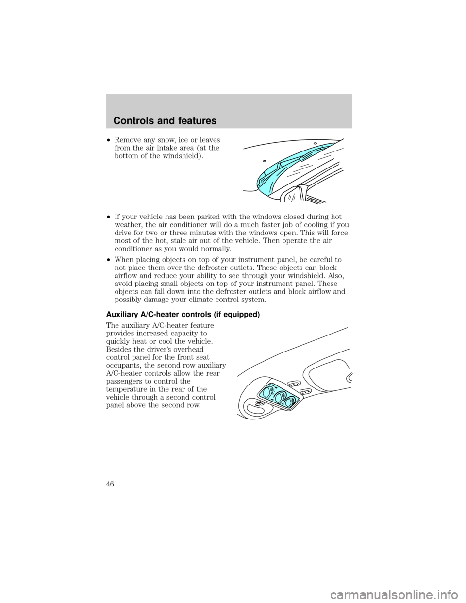
²Remove any snow, ice or leaves
from the air intake area (at the
bottom of the windshield).
²If your vehicle has been parked with the windows closed during hot
weather, the air conditioner will do a much faster job of cooling if you
drive for two or three minutes with the windows open. This will force
most of the hot, stale air out of the vehicle. Then operate the air
conditioner as you would normally.
²When placing objects on top of your instrument panel, be careful to
not place them over the defroster outlets. These objects can block
airflow and reduce your ability to see through your windshield. Also,
avoid placing small objects on top of your instrument panel. These
objects can fall down into the defroster outlets and block airflow and
possibly damage your climate control system.
Auxiliary A/C-heater controls (if equipped)
The auxiliary A/C-heater feature
provides increased capacity to
quickly heat or cool the vehicle.
Besides the driver's overhead
control panel for the front seat
occupants, the second row auxiliary
A/C-heater controls allow the rear
passengers to control the
temperature in the rear of the
vehicle through a second control
panel above the second row.
Controls and features
46
Page 47 of 216
In order for the auxiliary A/C-heater
controls to function, the driver's
auxiliary A/C-heater control must be
set to REAR.
The instrument panel climate
controls must be on in order for the
auxiliary A/C-heater to operate.
When the auxiliary A/C-heater control is set to FLOOR, airflow only
occurs from the third row seat floor vent located in the driver's side rear
quarter trim panel.
When the auxiliary A/C-heater control is set to PANEL, airflow occurs
from the overhead 2nd and 3rd row vents.
Turn the fan speed control knob to
the desired speed.
Turn the temperature control to the
desired temperature.
You can get warm or cool air
through either the overhead
registers or floor vent by turning the
auxiliary mode selector:
²Far left for airflow to the
overhead registers.
²Far right for airflow to the rear
floor vent.
WARM PANEL FLOOR COOL
REAR OFF
HI
HI
COOL WARM
OFFPANELFLOOR
DEFFLR
& DEF A/C
MAX
A/CPANEL &
FLOOR
LO
LO OFF
HI
WARM COOL
Controls and features
47
Page 124 of 216

Preparing to tow
Use the proper equipment for towing a trailer, and make sure it is
properly attached to your vehicle. See your dealer or a reliable trailer
dealer if you require assistance.
If your vehicle is not equipped with the factory heavy duty trailer tow
option, auxiliary coolers are recommended for the automatic
transmission system if you are planning on:
²traveling farther than 80 km (50 miles)
²towing in hilly terrain
²towing frequently
Hitches
Do not use hitches that clamp onto the vehicle's bumper or attach to the
axle. You must distribute the load in your trailer so that 10% of the total
weight of the trailer is on the tongue.
Load equalizing hitch
When hooking up a trailer using a load equalizing hitch, always use the
following procedure:
1. Park the unloaded vehicle on a level surface. With the ignition on and
all doors closed, allow the vehicle to stand for several minutes so that it
can level.
2. Turn the air suspension (if equipped) control to OFF.
3. Measure the height of a reference point on the front and rear bumpers
at the center of the vehicle.
4. Attach the trailer to the vehicle and adjust the hitch equalizers so that
the front bumper height is within 0±13 mm (0.5 in) of the reference
point. After proper adjustment, the rear bumper should be no higher
than in Step 3.
5. Turn the air suspension (if equipped) control to ON.
Adjusting an equalizing hitch so the rear bumper of the vehicle
is lower or higher than it was unloaded will defeat the function
of the load equalizing hitch and may cause unpredictable handling.
Driving
124
Page 132 of 216

Fuse/Relay
LocationFuse Amp
RatingDescription
7 5A Aux A/C Blower Relay, Console Blower
8 5A Radio, Remote Entry Module, GEM Module
9 Ð Not Used
10 Ð Not Used
11 30A Front Washer Pump Relay, Wiper Run/Park
Relay, Wiper Hi/LO Relay, Windshield Wiper
Motor, Rear Washer Pump Relay
12 Ð Not Used
13 20A Stop Lamp Switch (Lamps), Turn/Hazard
Flasher, Speed Control Module
14 15A Rear Wipers, Running Board Lamps,
Battery Saver Relay, Interior Lamp Relay,
Accessory Delay Relay (Power Windows)
15 5A Stop Lamp Switch, (Speed Control, Brake
Shift Interlock, ABS, PCM Module Inputs),
GEM Module
16 20A Headlamps (Hi Beams), Cluster (Hi Beam
Indicator)
17 10A Heated Mirrors, Heated Grid Switch
Indicator
18 5A Instrument Illumination (Dimmer Switch
Power)
19 Ð Not Used
20 5A Audio, Four Wheel Air Suspension (4WAS)
Module, GEM Module
21 15A Starter Relay, Fuse 20
22 10A Air Bag Module
23 10A Aux A/C, Heated Seats, Trailer Tow Battery
Charge, Turn/Hazard Flasher, Console
Blower Door Actuator
24 10A Climate Mode Switch (Blower Relay),
EATC (via fuse 7), EATC Blower Relay
25 5A 4 Wheel Anti-Lock Brake System (4WABS)
Module
Roadside emergencies
132
Page 135 of 216

Fuse/Relay
LocationFuse Amp
RatingDescription
12 10A* Rear Wipers
13 Ð Not Used
14 Ð Not Used
15 10A* Running Board Lamps
16 Ð Not Used
17 Ð Not Used
18 15A* Powertrain Control Module, Fuel Injectors,
Fuel Pump, Mass Air Flow Sensor
19 10A* Trailer Tow Stop and Right Turn Lamp
20 10A* Trailer Tow Stop and Left Turn Lamp
21 Ð Not Used
22 Ð Not Used
23 15A* Powertrain Control Module, HEGO Sensors,
Canister Vent
24 15A* Powertrain C ontrol Module, Automatic
Transmission, CMS Sensor
101 30A** Trailer Tow Battery Charge
102 50A** Four Wheel Antilock Brake Module
103 50A** Junction Block Battery Feed
104 30A** 4x4 Shift Motor & Clutch
105 40A** Climate Control Front Blower
106 Ð Not Used
107 Ð Not Used
108 30A** Trailer Tow Electric Brake
109 50A** Air Suspension Compressor
110 30A** Moonroof, Flip Windows and Heated Seats
111 50A** Ignition Switch Battery Feed (Start Circuit)
112 30A** Drivers Power Seat, Adjustable Pedals
113 50A** Ignition Switch Battery Feed (Run and
Accessory Circuits)
114 30A** Climate Control Auxiliary Blower
115 Ð Not Used
Roadside emergencies
135
Page 149 of 216
Do not start your engine with the air cleaner removed and do
not remove it while the engine is running.
OPENING THE HOOD
1. Inside the vehicle, pull the hood
release handle located under the
bottom of the instrument panel.
2. Go to the front of the vehicle and
release the auxiliary latch that is
located under the front center of
the hood.
3. Lift the hood until the lift
cylinders hold it open.
BRAKE
HOOD
Maintenance and care
149
Page 192 of 216
FluidFord Part
NameApplication Capacity
Engine coolant
3Premium Engine
Coolant4.6L V8 engine
with 1 row
radiator20.5 L
(21.7 quarts)
4.6L V8 engine
with 2 row
radiator21.8L
(23.0 quarts)
5.4L V8 engine
with 1 row
radiator22.6L
(23.9 quarts)
5.4L V8 engine
with 2 row
radiator24.1L
(25.5 quarts)
4.6L V8 engine
with 1 row
radiator and aux
rear heat21.7L
(22.9 quarts)
4.6L V8 engine
with 2 row
radiator and aux
rear heat23.5L
(24.8 quarts)
5.4L V8 engine
with 1 row
radiator and aux
rear heat24.9L
(26.3 quarts)
5.4L V8 engine
with 2 row
radiator and aux
rear heat26.4L
(27.9 quarts)
Front axle
lubricantMotorcraft SAE
75W90 Axle
Lubricant4x4 vehicles
1.8-2.0L
(3.5-3.7 pints)
Capacities and specifications
192