Page 2 of 208

ICONS
Indicates a safety alert. Read the
following section onWarnings.
Indicates vehicle information related
to recycling and other
environmental concerns will follow.
Correct vehicle usage and the
authorized disposal of waste
cleaning and lubrication materials are significant steps towards
protecting the environment.
Indicates a message regarding child
safety restraints. Refer toSeating
and safety restraintsfor more
information.
Indicates that this Owner Guide
contains information on this subject.
Please refer to the Index to locate
the appropriate section which will
provide you more information.
WARNINGS
Warnings provide information which may reduce the risk of personal
injury and prevent possible damage to others, your vehicle and its
equipment.
BREAKING-IN YOUR VEHICLE
There are no particular breaking-in rules for your vehicle. During the
first 1 600 km (1 000 miles) of driving, vary speeds frequently. This is
necessary to give the moving parts a chance to break in.
INFORMATION ABOUT THIS GUIDE
The information found in this guide was in effect at the time of printing.
Ford may change the contents without notice and without incurring
obligation.
Introduction
2
Page 7 of 208

Check engine
Your vehicle is equipped with a
computer that monitors the engine's
emission control system. This system
is commonly known as the On Board
Diagnostics System (OBD II). This
OBD II system protects the environment by ensuring that your vehicle
continues to meet government emission standards. The OBD II system also
assists the service technician in properly servicing your vehicle.
TheCheck Engineindicator light illuminates when the ignition is first
turned to the ON position to check the bulb. If it comes on after the engine
is started, one of the engine's emission control systems may be
malfunctioning. The light may illuminate without a driveability concern being
noted. The vehicle will usually be drivable and will not require towing.
What you should do if the check engine light illuminates
Light turns on solid:
This means that the OBD II system has detected a malfunction.
Temporary malfunctions may cause yourCheck Enginelight to
illuminate. Examples are:
1.
The vehicle has run out of fuel. (The engine may misfire or run poorly.)
2. Poor fuel quality or water in the fuel.
3. The fuel cap may not have been properly installed and securely
tightened.
These temporary malfunctions can be corrected by filling the fuel tank
with good quality fuel and/or properly installing and securely tightening
the gas cap. After three driving cycles without these or any other
temporary malfunctions present, theCheck Enginelight should turn off.
(A driving cycle consists of a cold engine startup followed by mixed
city/highway driving.) No additional vehicle service is required.
If theCheck Enginelight remains on, have your vehicle serviced at the
first available opportunity.
Light is blinking:
Engine misfire is occurring which could damage your catalytic converter.
You should drive in a moderate fashion (avoid heavy acceleration and
deceleration) and have your vehicle serviced at the first available
opportunity.
CHECK
ENGINE
Instrumentation
7
Page 15 of 208
Engine coolant temperature gauge
Indicates the temperature of the engine coolant. At normal operating
temperature, the needle remains within the normal area (the area
between the ªHº and ªCº). If it enters the red section, the engine is
overheating. Stop the vehicle as soon as safely possible, switch off the
ignition and let it cool. Refer toEngine coolantin theMaintenance
and carechapter.
Never remove the coolant recovery cap while the engine is
running or hot.
²Standard instrument cluster
²Optional instrument cluster
This gauge indicates the temperature of the engine coolant, not the
coolant level. If the coolant is not at its proper level the gauge indication
will not be accurate. If the gauge enters the red section, the engine
coolant andCheck Engine/Service Engine Soonindicators illuminate,
refer toWhat you should know about fail-safe coolingin the
Maintenance and care chapter.
TEMPH
C
N
O
R
M
H
C
Instrumentation
15
Page 23 of 208
PANEL DIMMER CONTROL
Use to adjust the brightness of the
instrument panel during headlight
and parklamp operation.
²Push up to brighten.
²Push down to dim.
HEADLAMP CONTROL
Rotate the headlamp control to the
first position to turn on the parking
lamps. Rotate to the second position
to also turn on the headlamps.
High beams
Push forward to activate.
Flash to pass
Pull toward you to activate and
release to deactivate.
PANEL
DIM
OFF
P
HI
LO
F
S
OFF
HI
LO
F
S
OFF
Controls and features
23
Page 65 of 208

Radio frequency information
The Federal Communications Commission (FCC) and the Canadian Radio
and Telecommunications Commission(CRTC) establish the frequencies
AM and FM stations may use for their broadcasts. Allowable frequencies
are:
AM 530, 540±1600, 1610 kHz
FM 87.9, 88.1±107.1, 107.9 MHz
Not all frequencies are used in a given area.
Radio reception factors
Three factors can affect radio reception:
²Distance/strength.The further an FM signal travels, the weaker it is.
The listenable range of the average FM station is approximately 40 km
(24 miles). This range can be affected by ªsignal modulation.º Signal
modulation is a process radio stations use to increase their
strength/volume relative to other stations.
²Terrain.Hills, mountains and tall buildings between your vehicle's
antenna and the radio station signal can cause FM reception problems.
Static can be caused on AM stations by power lines, electric fences,
traffic lights and thunderstorms. Moving away from an interfering
structure (out of its ªshadowº) returns your reception to normal.
²Station overload.Weak signals are sometimes captured by stronger
signals when you pass a broadcast tower. A stronger signal may
temporarily overtake a weaker signal and play while the weak station
frequency is displayed.
The audio system automatically switches to single channel reception if it
will improve the reception of a station normally received in stereo.
Audio system warranties and service
Refer to the ªWarranty Guideº for audio system warranty information.
If service is necessary, see your dealer or a qualified technician.
Controls and features
65
Page 67 of 208
POSITIONS OF THE IGNITION
1. ACCESSORY, allows the electrical
accessories such as the radio to
operate while the engine is not
running.
2. LOCK, locks the steering wheel,
automatic transmission gearshift
lever and allows key removal.
3. OFF, shuts off the engine and all
accessories without locking the
steering wheel.
4. ON, all electrical circuits operational. Warning lights illuminated. Key
position when driving.
5. START, cranks the engine. Release the key as soon as the engine
starts.
TILT STEERING
Pull the tilt steering control toward
you to move the steering wheel up
or down. Hold the control while
adjusting the wheel to the desired
position, then release the control.
Never adjust the steering wheel when the vehicle is moving.
3
1
2
5
4
Controls and features
67
Page 85 of 208

Changes or modifications not expressly approved by the party
responsible for compliance could void the user's authority to
operate the equipment.
Illuminated entry
The interior lamps illuminate when the remote entry system is used to
unlock the door(s) or sound the personal alarm.
The system automatically turns off after 25 seconds or when the ignition
is turned to the START or ACC position. The dome lamp control (if
equipped) mustnotbe set to the OFF position for the illuminated entry
system to operate.
The inside lights will not turn off if:
²they have been turned on with the dimmer control or
²any door is open.
The battery saver will shut off the interior lamps 30 minutes after the
last door is closed or after 10 minutes if the door is left open.
Replacing the battery
The remote transmitter is powered by one coin type three-volt lithium
battery CR2032 or equivalent. Typical operating range will allow you to
be up to 10 meters (33 feet) away from your vehicle. A decrease in
operating range can be caused by:
²weather conditions
²nearby radio towers
²structures around the vehicle
²other vehicles parked next to the vehicle
To replace the battery:
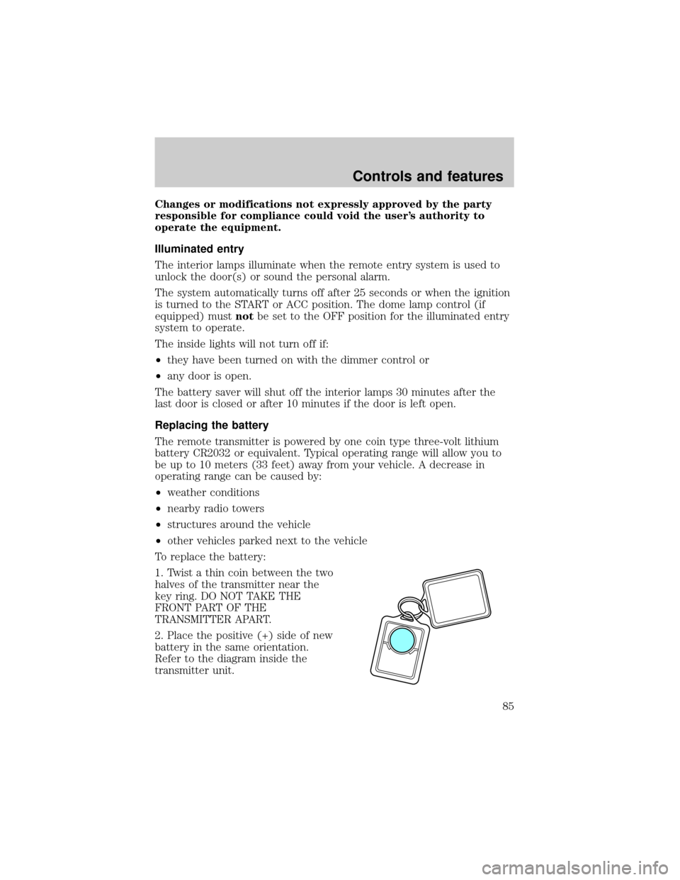
1. Twist a thin coin between the two
halves of the transmitter near the
key ring. DO NOT TAKE THE
FRONT PART OF THE
TRANSMITTER APART.
2. Place the positive (+) side of new
battery in the same orientation.
Refer to the diagram inside the
transmitter unit.
Controls and features
85
Page 110 of 208

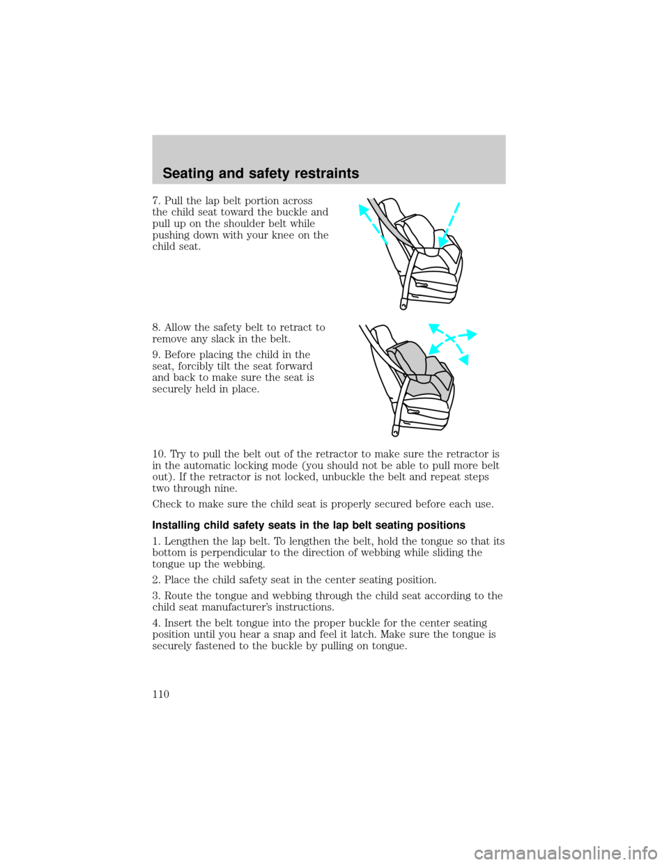
7. Pull the lap belt portion across
the child seat toward the buckle and
pull up on the shoulder belt while
pushing down with your knee on the
child seat.
8. Allow the safety belt to retract to
remove any slack in the belt.
9. Before placing the child in the
seat, forcibly tilt the seat forward
and back to make sure the seat is
securely held in place.
10. Try to pull the belt out of the retractor to make sure the retractor is
in the automatic locking mode (you should not be able to pull more belt
out). If the retractor is not locked, unbuckle the belt and repeat steps
two through nine.
Check to make sure the child seat is properly secured before each use.
Installing child safety seats in the lap belt seating positions
1. Lengthen the lap belt. To lengthen the belt, hold the tongue so that its
bottom is perpendicular to the direction of webbing while sliding the
tongue up the webbing.
2. Place the child safety seat in the center seating position.
3. Route the tongue and webbing through the child seat according to the
child seat manufacturer's instructions.
4. Insert the belt tongue into the proper buckle for the center seating
position until you hear a snap and feel it latch. Make sure the tongue is
securely fastened to the buckle by pulling on tongue.
Seating and safety restraints
110