1999 DODGE RAM fuel tank removal
[x] Cancel search: fuel tank removalPage 982 of 1691
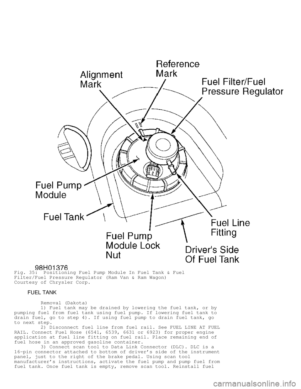
Fig. 35: Positioning Fuel Pump Module In Fuel Tank & Fuel
Filter/Fuel Pressure Regulator (Ram Van & Ram Wagon)
Courtesy of Chrysler Corp.
FUEL TANK
Removal (Dakota)
1) Fuel tank may be drained by lowering the fuel tank, or by
pumping fuel from fuel tank using fuel pump. If lowering fuel tank to
drain fuel, go to step 4). If using fuel pump to drain fuel tank, go
to next step.
2) Disconnect fuel line from fuel rail. See FUEL LINE AT FUEL
RAIL. Connect Fuel Hose (6541, 6539, 6631 or 6923) for proper engine
application at fuel line fitting on fuel rail. Place remaining end of
fuel hose in an approved gasoline container.
3) Connect scan tool to Data Link Connector (DLC). DLC is a
16-pin connector attached to bottom of driver's side of the instrument
panel, just to the right of the brake pedal. Using scan tool
manufacturer's instructions, activate the fuel pump and pump fuel from
fuel tank. Once fuel tank is empty, remove scan tool. Reinstall fuel
Page 985 of 1691
1) To install, reverse removal procedure. If installing small
vent tube and large fill tube on fuel tank, ensure fuel tank fittings
are clean.
2) Install disconnect fitting on fuel tank fitting until
disconnect fitting snaps onto fuel tank fitting. Pull on small vent
tube or and large fill tube to ensure disconnect fitting is locked on
fuel tank fitting. To verify proper installation of disconnect
fitting, ensure the distance between release sleeve and top of fuel
tank fitting is .50" (12.7 mm) on small vent tube or .25" (6.4 mm) o\
n
large fill tube. See Fig. 37.
3) Install fuel lines on fuel filter/fuel pressure regulator
on fuel pump module using proper procedure. See FUEL LINE DISCONNECT
FITTINGS under FUEL SYSTEM.
CAUTION: DO NOT overtighten fuel tank strap retaining nuts during
installation.
4) Tighten fuel tank strap retaining nuts to specification.
See TORQUE SPECIFICATIONS. To install remaining components, reverse
removal procedure. Start engine and check for fuel leaks.
Removal (Durango)
1) Fuel tank may be drained by removing vent hose from rear
of fuel tank, or by pumping fuel from fuel tank using the fuel pump if
fuel pump is operating. If removing vent hose from fuel tank to drain
the fuel, go to step 4). If using fuel pump to drain the fuel tank, go
to next step.
2) Disconnect fuel line from fuel rail. See FUEL LINE AT FUEL
RAIL under FUEL SYSTEM. Connect Fuel Hose (6541, 6539, 6631 or 6923)
for proper engine application at fuel line fitting on fuel rail. Place
remaining end of fuel hose in an approved gasoline container.
3) Connect scan tool to Data Link Connector (DLC). DLC is a
16-pin connector attached to bottom of driver's side of the instrument
panel, just to the right of the brake pedal. Using scan tool
manufacturer's instructions, activate the fuel pump and pump fuel from
fuel tank. Once fuel tank is empty, remove scan tool. Reinstall fuel
line on fuel rail using proper procedure. Go to step 5).
4) Release fuel pressure from fuel system. See FUEL SYSTEM
PRESSURE RELEASE. Ensure negative battery cable is disconnected.
Remove fuel tank cap to release any residual fuel tank pressure.
5) Raise and support vehicle. Remove necessary skid plates
for access to fuel tank. Disconnect vent and filler hose from rear of
fuel tank. If fuel tank was not previously drained, place drain hose
in vent hose fitting at rear of fuel tank. Drain fuel from fuel tank
into an approved gasoline container.
6) Support fuel tank with transmission jack. Remove fuel tank
strap retaining nuts. Position fuel tank straps toward outside of
vehicle. Slightly lower fuel tank. Ensure rear of fuel tank is higher
than front of fuel tank to prevent any spilling any remaining fuel in
fuel tank.
7) Disconnect fuel line from fuel filter/fuel pressure
regulator on fuel pump module using proper procedure for fuel line
disconnect fitting. See FUEL LINE DISCONNECT FITTINGS. Fuel pump
module is located on top of fuel tank. See Fig. 28. Disconnect
electrical connector at fuel pump module. Disconnect vapor line from
rollover valves on top of fuel tank and EVAP line from fuel pump
module. Lower fuel tank from vehicle.
CAUTION: DO NOT overtighten fuel tank strap retaining nuts during
installation.
Installation
1) To install, reverse removal procedure. Install fuel lines
Page 986 of 1691
on fuel filter/fuel pressure regulator on fuel pump module using
proper procedure. See FUEL LINE DISCONNECT FITTINGS.
2) Tighten fuel tank strap retaining nuts to specification.
See TORQUE SPECIFICATIONS. Start engine and check for fuel leaks.
Removal (Ram Pickup)
1) Fuel tank may be drained by lowering fuel tank, or by
pumping fuel from fuel tank using the fuel pump if fuel pump is
operating. If lowering fuel tank to drain the fuel, go to step 4). If
using fuel pump to drain the fuel tank, go to next step.
2) Disconnect fuel line from fuel rail. See FUEL LINE AT FUEL
RAIL. Connect Fuel Hose (6541, 6539, 6631 or 6923) for proper engine
application at fuel line fitting on fuel rail. Place remaining end of
fuel hose in an approved gasoline container.
3) Connect scan tool to Data Link Connector (DLC). DLC is a
16-pin connector attached to bottom of driver's side of the instrument
panel, just straight above the accelerator pedal. Using scan tool
manufacturer's instructions, activate the fuel pump and pump fuel from
fuel tank. Once fuel tank is empty, remove scan tool. Reinstall fuel
line on fuel rail using proper procedure. Go to step 5).
4) Release fuel pressure from fuel system. See FUEL SYSTEM
PRESSURE RELEASE. Ensure negative battery cable is disconnected.
Remove fuel tank cap to release any residual fuel tank pressure.
5) Raise and support vehicle. Open fuel tank filler door.
Remove fuel tank filler tube assembly-to-body screws. Support fuel
tank with transmission jack. Remove fuel tank strap retaining nuts.
6) Slightly lower fuel tank. If fuel tank was not previously
drained, slightly rotate fuel tank so vent hose and filler hose on
fuel tank are above the fuel level in the fuel tank to prevent fuel
leakage when hoses are disconnected. Vent hose and filler hose attach
to fitting on the fuel tank. See Fig. 29.
7) Disconnect vent hose from vent hose fitting on fuel tank.
If fuel tank was previously drained, go to next step. If fuel tank was
not previously drained, place drain hose in vent hose fitting on fuel
tank. Drain fuel from fuel tank into an approved gasoline container.
Go to next step.
8) Disconnect filler hose from filler hose fitting on fuel
tank. Disconnect electrical connector at fuel pump module. Fuel pump
module is located on top of fuel tank. See Fig. 29.
9) Disconnect fuel line from fuel filter/fuel pressure
regulator on fuel pump module using proper procedure for fuel line
disconnect fitting. See FUEL LINE DISCONNECT FITTINGS under FUEL
SYSTEM.
10) Disconnect necessary vapor hoses from rollover valves on
top of fuel tank or fuel pump module. See Fig. 29. Lower fuel tank
from vehicle.
CAUTION: DO NOT overtighten fuel tank strap retaining nuts during
installation.
Installation
1) To install, reverse removal procedure. Install fuel lines
on fuel filter/fuel pressure regulator on fuel pump module using
proper procedure. See FUEL LINE DISCONNECT FITTINGS.
2) Tighten fuel tank strap retaining nuts to specification.
See TORQUE SPECIFICATIONS. Start engine and check for fuel leaks.
Removal (Ram Van & Ram Wagon)
1) Fuel tank may be drained by siphoning fuel out through
small vent hose on fuel and vent hose fitting assembly on fuel tank,
or by pumping fuel from fuel tank using the fuel pump if fuel pump is
operating. If siphoning fuel out through small vent hose on fuel and
vent hose fitting assembly on fuel tank, go to step 4). If using fuel
Page 988 of 1691
fitting assembly out of the plastic shield. Use care not to damage
fill and vent fitting assembly. Disconnect fuel line from fuel
filter/fuel pressure regulator on fuel pump module using proper
procedure for fuel line disconnect fitting. See FUEL LINE DISCONNECT
FITTINGS. Fuel pump module is located on top of fuel tank. See Fig. 30
.
11) Disconnect electrical connector at fuel pump module.
Disconnect vapor hoses from rollover valves on top of fuel tank. See
Fig. 30 . Lower fuel tank from vehicle. Use care not to damage fill and
vent hose fitting assembly.
Installation
1) To install, reverse removal procedure. Install fuel lines
on fuel filter/fuel pressure regulator on fuel pump module using
proper procedure. See FUEL LINE DISCONNECT FITTINGS.
2) Ensure retaining tabs on fill and vent hose fitting
assembly fully engage the plastic shield. Tighten fuel tank strap
retaining nuts to specification. See TORQUE SPECIFICATIONS. Start
engine and check for fuel leaks.
FUEL RAIL & INJECTORS
Removal (Dakota 2.5L)
1) Release fuel pressure from fuel system. See FUEL SYSTEM
PRESSURE RELEASE. Ensure negative battery cable is disconnected.
2) Disconnect air inlet duct at throttle body for access to
fuel rail. Disconnect vent line from fuel damper at end of fuel rail
(if equipped).
3) Note electrical connector location on injectors for
installation reference. Disconnect electrical connectors at injectors.
Disconnect fuel line from fuel rail. See FUEL LINE AT FUEL RAIL.
Disconnect control cables at throttle body. Remove control cable
mounting bracket from intake manifold for access to fuel rail.
4) Remove fuel rail bolts. Ensure area around injectors and
intake manifold is clean. Using rocking motion, remove fuel rail with
injectors from intake manifold.
5) If removing injector from fuel rail, remove retaining clip
from fuel rail and injector. Retaining clip is located at top of
injector and fuel rail. Remove injector with "O" ring from fuel rail.
Installation
1) If installing injector on fuel rail, install NEW "O" ring
on injector. Coat "O" ring on injector with engine oil. Install
injector on fuel rail. Install retaining clip on injector and fuel
rail.
2) To install remaining components, reverse removal procedure
using NEW "O" ring at bottom of each injector. Coat "O" ring on
injector with engine oil before installing injectors and fuel rail.
3) Tighten fuel rail bolts to specification. See TORQUE
SPECIFICATIONS. Install fuel line on fuel rail using proper procedure.
See FUEL LINE AT FUEL RAIL. Start engine and check for leaks.
Removal (Dakota 3.9L, 5.2L & 5.9L, Durango, Ram Pickup 3.9L,
5.2L & 5.9L, Ram Van & Ram Wagon)
1) Release fuel pressure from fuel system. See FUEL SYSTEM
PRESSURE RELEASE. Ensure negative battery cable is disconnected.
2) On Ram Van and Ram Wagon, remove engine cover. On all
models, remove air cleaner. Remove throttle body from intake manifold.
See THROTTLE BODY. On A/C equipped models, remove A/C compressor-to-
intake manifold support brace at rear of A/C compressor.
3) On all models, note electrical connector location on
injectors for installation reference. Disconnect electrical connectors
at injectors. Disconnect any necessary wiring electrical connectors
Page 991 of 1691
body. Remove throttle body bolts, throttle body and gasket. To
install, reverse removal procedure using NEW gasket. Tighten throttle
body bolts to specification. See TORQUE SPECIFICATIONS.
Removal & Installation (Ram Pickup 8.0L)
1) Remove air cleaner cover. Remove air cleaner housing-to-
throttle body nuts and air cleaner housing from throttle body.
Disconnect electrical connectors, control cables and vacuum hoses at
throttle body. Remove throttle body nuts, throttle body and gasket
from upper intake manifold.
2) To install, reverse removal procedure using NEW gasket.
Tighten throttle body nuts and air cleaner housing-to-throttle body
nuts to specification. See TORQUE SPECIFICATIONS.
EMISSION SYSTEMS
EVAP CANISTER
Removal & Installation (Dakota & Durango)
1) EVAP canister is located on mounting bracket attached to
inside of driver's side frame rail, just in front of the fuel tank.
Raise and support vehicle.
2) Note location of vacuum hoses on EVAP canister for
installation reference. Disconnect vacuum hoses from EVAP canister.
Remove EVAP canister-to-mounting bracket nut and EVAP canister.
3) To install, reverse removal procedure. Ensure the pins on
EVAP canister engage with grommets on mounting bracket. Tighten EVAP
canister-to-mounting bracket nut to specification. See TORQUE
SPECIFICATIONS.
Removal & Installation (Ram Pickup)
1) Two EVAP canisters are used. EVAP canisters are located on
mounting bracket attached to outside of passenger's side frame rail,
just behind the cab.
2) Note location of vacuum hoses on EVAP canister for
installation reference. Disconnect vacuum hoses from EVAP canister.
Remove EVAP canister-to-mounting bracket nuts and EVAP canisters.
3) To install, reverse removal procedure. Tighten EVAP
canister-to-mounting bracket nut to specification. See TORQUE
SPECIFICATIONS.
Removal & Installation (Ram Van & Ram Wagon)
1) Two EVAP canisters are used. EVAP canisters are located on
mounting bracket under driver's side of vehicle, behind driver's side
door opening.
2) Remove nuts and EVAP canister mounting bracket from the
body. Slightly lower EVAP canisters. Note location of vacuum hoses on
EVAP canister for installation reference. Disconnect vacuum hoses from
EVAP canister. Remove EVAP canister-to-mounting bracket nuts and EVAP
canisters.
3) To install, reverse removal procedure. Tighten EVAP
canister-to-mounting bracket nut to specification. See TORQUE
SPECIFICATIONS. When installing mounting bracket, ensure locating tabs
at top of mounting bracket engage with openings on the body. Tighten
EVAP canister mounting bracket-to body nuts to specification. See
TORQUE SPECIFICATIONS.
EVAP LEAK DETECTION PUMP
NOTE: EVAP leak detection pump may also be referred to as Leak
Detection Pump (LDP).