Page 164 of 193

Downloaded from www.Manualslib.com manuals search engine INTAKE MANIFOLD
REMOVAL
(1) Disconnect the battery negative cable.
(2) Drain the cooling system. Refer to COOLING
SYSTEM.
(3) Remove the A/C compressor. Refer to HEAT-
ING and AIR CONDITIONING.
(4) Remove the generator. Refer to CHARGING
SYSTEM.
(5) Remove the accessory drive bracket.
(6) Remove the air cleaner assembly and air inlet
hose.
(7) Perform the fuel pressure release procedure.
Refer to FUEL SYSTEM.
(8) Disconnect the fuel supply line from the fuel
rail. Refer to FUEL SYSTEM.
(9) Disconnect the accelerator linkage and, if so
equipped, the speed control and transmission kick-
down cables.
(10) Remove the distributor cap and wires.
(11) Disconnect the coil wires.
(12) Disconnect the coolant temperature sending
unit wire.
(13) Disconnect the heater hoses and bypass hose.
(14) Remove the closed crankcase ventilation and
evaporation control systems.
(15) Remove intake manifold bolts.
(16) Lift the intake manifold and throttle body out
of the engine compartment as an assembly.
(17) Remove and discard the flange side gaskets
and the front and rear cross-over gaskets.
(18) Remove the throttle body bolts and lift the
throttle body off the intake manifold (Fig. 40). Dis-
card the throttle body gasket.
INSTALLATION
(1) If the plenum pan was removed, position pan
gasket and pan.
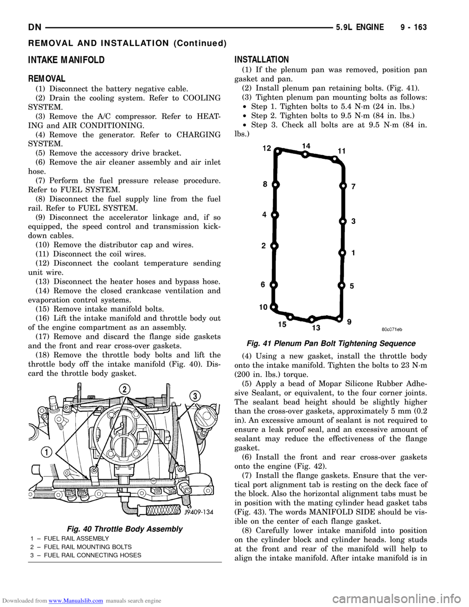
(2) Install plenum pan retaining bolts. (Fig. 41).
(3) Tighten plenum pan mounting bolts as follows:
²Step 1. Tighten bolts to 5.4 N´m (24 in. lbs.)
²Step 2. Tighten bolts to 9.5 N´m (84 in. lbs.)
²Step 3. Check all bolts are at 9.5 N´m (84 in.
lbs.)
(4) Using a new gasket, install the throttle body
onto the intake manifold. Tighten the bolts to 23 N´m
(200 in. lbs.) torque.
(5) Apply a bead of Mopar Silicone Rubber Adhe-
sive Sealant, or equivalent, to the four corner joints.
The sealant bead height should be slightly higher
than the cross-over gaskets, approximately 5 mm (0.2
in). An excessive amount of sealant is not required to
ensure a leak proof seal, and an excessive amount of
sealant may reduce the effectiveness of the flange
gasket.
(6) Install the front and rear cross-over gaskets
onto the engine (Fig. 42).
(7) Install the flange gaskets. Ensure that the ver-
tical port alignment tab is resting on the deck face of
the block. Also the horizontal alignment tabs must be
in position with the mating cylinder head gasket tabs
(Fig. 43). The words MANIFOLD SIDE should be vis-
ible on the center of each flange gasket.
(8) Carefully lower intake manifold into position
on the cylinder block and cylinder heads. long studs
at the front and rear of the manifold will help to
align the intake manifold. After intake manifold is in
Fig. 40 Throttle Body Assembly
1 ± FUEL RAIL ASSEMBLY
2 ± FUEL RAIL MOUNTING BOLTS
3 ± FUEL RAIL CONNECTING HOSES
Fig. 41 Plenum Pan Bolt Tightening Sequence
DN5.9L ENGINE 9 - 163
REMOVAL AND INSTALLATION (Continued)
Page 165 of 193

Downloaded from www.Manualslib.com manuals search engine place, inspect to make sure seals are in place.
Remove alignment studs if used.
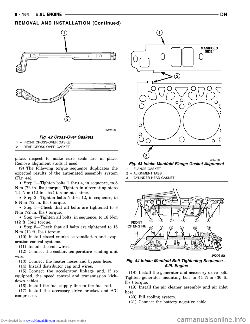
(9) The following torque sequence duplicates the
expected results of the automated assembly system
(Fig. 44).
²Step 1ÐTighten bolts 1 thru 4, in sequence, to 8
N´m (72 in. lbs.) torque. Tighten in alternating steps
1.4 N´m (12 in. lbs.) torque at a time.
²Step 2ÐTighten bolts 5 thru 12, in sequence, to
8 N´m (72 in. lbs.) torque.
²Step 3ÐCheck that all bolts are tightened to 8
N´m (72 in. lbs.) torque.
²Step 4ÐTighten all bolts, in sequence, to 16 N´m
(12 ft. lbs.) torque.
²Step 5ÐCheck that all bolts are tightened to 16
N´m (12 ft. lbs.) torque.
(10) Install closed crankcase ventilation and evap-
oration control systems.
(11) Install the coil wires.
(12) Connect the coolant temperature sending unit
wire.
(13) Connect the heater hoses and bypass hose.
(14) Install distributor cap and wires.
(15) Connect the accelerator linkage and, if so
equipped, the speed control and transmission kick-
down cables.
(16) Install the fuel supply line to the fuel rail.
(17) Install the accessory drive bracket and A/C
compressor.(18) Install the generator and accessory drive belt.
Tighten generator mounting bolt to 41 N´m (30 ft.
lbs.) torque.
(19) Install the air cleaner assembly and air inlet
hose.
(20) Fill cooling system.
(21) Connect the battery negative cable.
Fig. 42 Cross-Over Gaskets
1 ± FRONT CROSS-OVER GASKET
2 ± REAR CROSS-OVER GASKET
Fig. 43 Intake Manifold Flange Gasket Alignment
1 ± FLANGE GASKET
2 ± ALIGNMENT TABS
3 ± CYLINDER HEAD GASKET
Fig. 44 Intake Manifold Bolt Tightening SequenceÐ
5.9L Engine
9 - 164 5.9L ENGINEDN
REMOVAL AND INSTALLATION (Continued)
Page 182 of 193

Downloaded from www.Manualslib.com manuals search engine INSTALLATION
Thoroughly clean inside of cup plug hole in cylin-
der block or head. Be sure to remove old sealer.
Be certain the new plug is cleaned of all oil or
grease.
(1) Coat edges of plug and core hole with Mopart
Gasket Maker, or equivalent.
CAUTION: DO NOT drive cup plug into the casting,
as restricted coolant flow can result and cause seri-
ous engine problems.
(2) Using proper plug drive, drive cup plug into
hole. The sharp edge of the plug should be at least
0.50 mm (0.020 in.) inside the lead-in chamfer.
(3) It is not necessary to wait for curing of the
sealant. The cooling system can be filled and the
vehicle placed in service immediately.
DISASSEMBLY AND ASSEMBLY
OIL PUMP
DISASSEMBLE
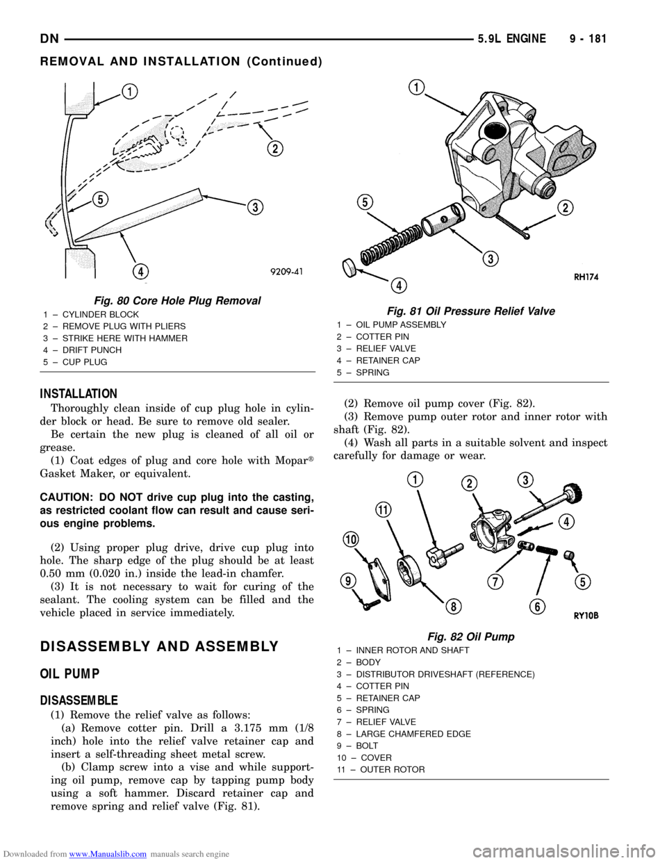
(1) Remove the relief valve as follows:
(a) Remove cotter pin. Drill a 3.175 mm (1/8
inch) hole into the relief valve retainer cap and
insert a self-threading sheet metal screw.
(b) Clamp screw into a vise and while support-
ing oil pump, remove cap by tapping pump body
using a soft hammer. Discard retainer cap and
remove spring and relief valve (Fig. 81).(2) Remove oil pump cover (Fig. 82).
(3) Remove pump outer rotor and inner rotor with
shaft (Fig. 82).
(4) Wash all parts in a suitable solvent and inspect
carefully for damage or wear.
Fig. 80 Core Hole Plug Removal
1 ± CYLINDER BLOCK
2 ± REMOVE PLUG WITH PLIERS
3 ± STRIKE HERE WITH HAMMER
4 ± DRIFT PUNCH
5 ± CUP PLUGFig. 81 Oil Pressure Relief Valve
1 ± OIL PUMP ASSEMBLY
2 ± COTTER PIN
3 ± RELIEF VALVE
4 ± RETAINER CAP
5 ± SPRING
Fig. 82 Oil Pump
1 ± INNER ROTOR AND SHAFT
2 ± BODY
3 ± DISTRIBUTOR DRIVESHAFT (REFERENCE)
4 ± COTTER PIN
5 ± RETAINER CAP
6 ± SPRING
7 ± RELIEF VALVE
8 ± LARGE CHAMFERED EDGE
9 ± BOLT
10 ± COVER
11 ± OUTER ROTOR
DN5.9L ENGINE 9 - 181
REMOVAL AND INSTALLATION (Continued)
Page:
< prev 1-8 9-16 17-24