1999 BMW 540i engine coolant
[x] Cancel search: engine coolantPage 453 of 1002

Downloaded from www.Manualslib.com manuals search engine
Fuel lnjection
Table e. Bosch 5.2.1 ECM pin assignments
Pin
Isignal 1 Description 1 Note
Connector
X60003
1
2
3
4
5
6
7 8
9 10
11
12
13
14
15
16
17
18
19
20
21
ate alr empe
Output
Output
Output
Ground
Ground
Output
Output Input
Input
Input
Ground
22
23
24
25
26
27
28
29
30
Injection signal
Injection signal
Signal, evaporative emission valve
Not used
Not used
Ground for electronic components
Not used
Not used
Hot film mass air flow sensor ground
Throttle position sensor voltage supply
Signal, engine coolant temperature sensor
Hot
film mass air flow sensor signal
Throttle position sensor slider voltage
Shield, throttle potentiometer (DK) Not used
Injection signal
Injection signal
Not used
Not used
Input
Input
Input
Ground
Output
Output Evaporative emission
valve
Ground point right-hand drive
Ground connector
X6460
Hot film mass air flow sensor
Throttle position sensor
Signal, secondary air injection pump valve
Terminal
30 voltage supply
Alternator
D+ (terminal 61) signal
injection signal
Injection
signal
Not used
Not used
Not used
Not used
Camshaft position sensor signal
Ground Dual temperature switch
Hot film mass air flow sensor
Throttle position sensor
Throttle position sensor
Cylinder
8 fuel injection valve
Cylinder
5 fuel injection valve
Secondary air injection pump
valve
Starter
Alternator (generator)
Cylinder
7 fuel injection valve
Cylinder 6 fuel injection valve
Camshaft position sensor (Hall effect) Dual temperature
switch
Page 461 of 1002

Downloaded from www.Manualslib.com manuals search engine
Fuel Injection I
Engine coolant temperature (ECT) sensor,
testing
The ECT sensor is located on the front of the engine in the
coolant~thermostat flange. The ECT sensor is a dual temper-
ature sensor. One circuit provides coolant temperature infor-
mation to the ECM while the other circuit provides coolant
temperature information to the instrument cluster.
The ECM determines the correct ignition timing and
airlfuel
mixture required for the engine by monitoring an applied volt-
age
(5 vdc) to the sensor. Thevoltage drop across the sensor
varies as the coolant temperature (sensor resistance) chang-
es.
NOTE-
The ECT sensor is an NTC (negative temperature coeffi-
cient) type sensor. In other words, as the temperature rises,
resistance through the sensor decreases.
If the ETC sensor input is faulty or non-plausible, the MIL is il-
luminated when OBD
II fault criteria are exceeded. The ECM
assumes a substitute value
(80" C/ 176°F) to maintain engine
operation. The ignition timing is set to a
conse~ativelsafe ba-
sic setting.
Disconnect harness from
ECTsensor (A) at coolant flange at
front of engine.
- Check ECT sensor resistance using a multimeter at sensor
terminals
3 and 4. Peel back protective boot (B) to ID termi-
nal numbers on connector housing.
I ECT sensor resistance @ 20" C (68°F) I 2.2 - 2.7 lkCi
Engine coolant temperature (ECT) sensor,
replacing
I WARNING-
/ Due to risk ofpersonal injury, be sure the engine is cold be- I
I fore replacin~~~~sensor. -
-
I
- Disconnect ECT sensor harness.
- Unscrew ECT sensor from cylinder head and install new sen-
sor.
Use new copper sealing washers when installing sensor.
Replace any lost coolant.
Tightening torque
ECT sensor to coolant flange 13 Nm (10 it-lb)
Page 469 of 1002

Downloaded from www.Manualslib.com manuals search engine
Fuel Injection I
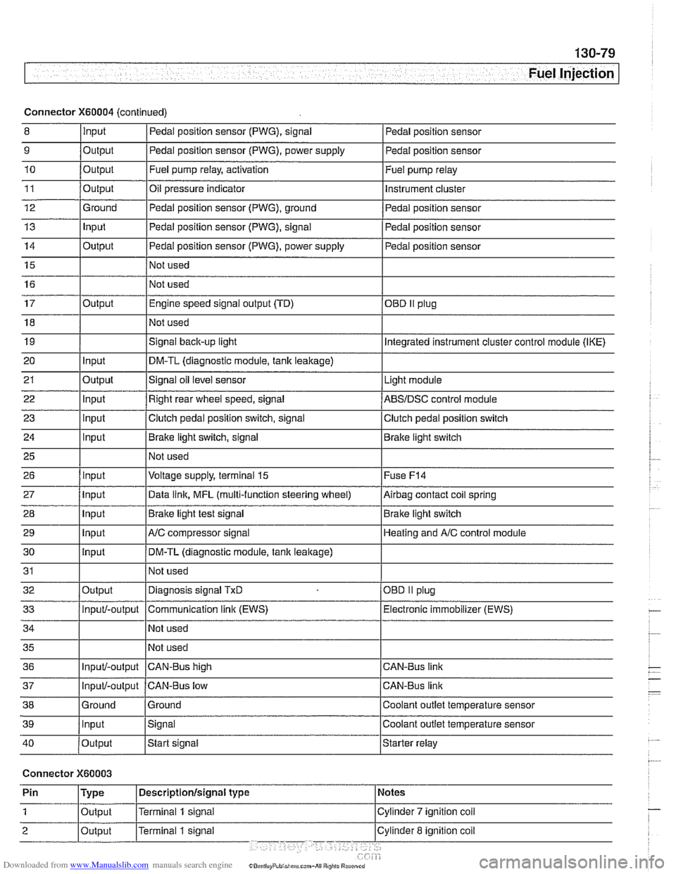
Connector X60004 (continued)
8 10
11
12
13
14
15
16
9
Output 0
Input
17
18
19
20
21
22
23
24
25
26
27
28
29
30
31
32
33
34
35
36
39
llnput lsignal l~oolant outlet temperature sensor
Output
Output
Ground
Input
Output
I I - I
40 /output Istart signal Istarter relay
Pedal position sensor (PWG), signal
Output Input
Output
input
Input
Input
Input
Input
Input
input
Input
Output
Input/-output
Input/-output
37
Connector X60003
Pedal position sensor
Fuel pump relay, activation
Oil pressure indicator Pedal position sensor (PWG), ground
Pedal position sensor (PWG), signal
Pedal position sensor (PWG), power supply
Not used
Not used Fuel
pump relay
Instrument cluster
Pedal position sensor
Pedal position sensor
Pedal position sensor
Engine speed signal output (TD)
Not used
Signal
back-up light
DM-TL (diagnostic module,
tank leakage)
Signal oil level sensor
Right rear wheel speed, signal
Clutch pedal position switch, signal
Brake light switch, signal
Not used
Voltage supply, terminal
15
Data link, MFL (multi-function steering wheel)
Brake light test signal
AJC compressor signal
DM-TL (diagnostic module, tank
leakage)
Not used
Diagnosis signal
TxD
Communication link (EWS)
Not used
Not used
CAN-BUS hiqh
38 1 Ground l~round I Coolant outlet temperature sensor
OED II plug
Integrated instrument cluster control module (IKE)
Light module
ABSIDSC control module
Clutch pedal position switch
Brake light switch
Fuse
F14
Airbag contact coil spring
Brake light switch
Heating and
A/C control module
OBD
II plug
Electronic immobilizer (EWS)
CAN-Bus link
CAN-Bus link
Input/-output CAN-Bus low
Page 497 of 1002

Downloaded from www.Manualslib.com manuals search engine
176 Radiator and Cooling System
General ........................... .I7 0.2
Special tools
........................ .I7 0.2
Cooling system overview
(M52 TU shown. others similar) ......... .I7 0.3
Coolant pump
....................... .I7 0.3
Thermostat
......................... .I7 0.3
Mechanical thermostat (M52 engine)
..... .I7 0.4
Electrically heated thermostat
.......... .I7 0.4
Radiator and expansion tank
........... .I7 0.4
Mechanical cooling fan with viscous clutch
.I7 0.4
Electric (auxiliary) cooling fan ........... .I7 0.4
Transmission fluid heat exchanger
....... .I7 0.5
Warnings and cautions
................ .I7 0.7
Troubleshooting ................... .I7 0.7
Cooling system inspection
............. .I7 0.8
Cooling system pressure test
........... .I7 0.9
Combustion chamber leak test
......... .I7 0.10
Thermostat
........................ .I7 0.1 0
Cooling System Service ........... 170-10
Coolant. draining and filling
(6-cylinder models)
.................. 170-1 0
Coolant. draining and filling (V-8 models)
. 170-12
Cooling system. bleeding
............. 170-14
Mechanical (viscous clutch) cooling fan.
removing and installing
............... 170-14
Electric cooling fan.
removing and installing
............... 170-15
Thermostat. removing and installing
(M52engine) ....................... 170-16
Thermostat. removing and installing
(M52 TU or M54 engine) .............. 170-17
Thermostat. removing and installing (V-8 models)
....................... 170-1 8
Coolant pump. replacing (6-cylinder models)
.................. 170-1 9
Coolant pump. replacing (V-8 models) ... 170-20
Radiator. removing and installing
....... 170-22
Expansion tank. removing and
installing . . 170-24
Page 499 of 1002

Downloaded from www.Manualslib.com manuals search engine
- -
L- -
--
-. - - - Radiator and Cooling sYstelll/ --
Cooling system overview
(M52 TU shown, others similar)
Coolant pump
A centrifugal coolant pump is mounted to the front of the en-
gine. The belt-driven pump circulates coolant through the
system whenever the engine is running.
Thermostat
Two types of thermostats are used in the cars covered by this
manual. 6-cylinder models built up to
911 998 (M52 engine)
use a conventional mechanical thermostat. All
V-8 models
and 6-cylinder models from
911998 use an electrically heated
thermostat.
Page 500 of 1002

Downloaded from www.Manualslib.com manuals search engine
-
I Radiator and Cooling System
Mechanical thermostat
(M52 engine)
4 The mechanical thermostat relies on coolant temperature to
operate. While coolant is cold, it remains closed, and circu-
lating coolant bypasses the radiator for rapid engine warm
up. At higher coolant temperature, the thermostat progres-
sively opens to allow coolant flow through the radiator, thus
controlling engine temperature. Port
A restricts coolant flow
from radiator, and port
B restricts coolant flow to radiator.
Electrically heated thermostat
4 The electrically heated thermostat is DME map-controlled.
The engine control module (ECM) activates the thermostat to
maintain engine coolant temperature within a narrow range.
In case of failure of the electronics, the mechanical function of
the thermostat acts as a fail-safe.
Radiator and expansion tank
The radiator is a crossflow design. An expansion tank pro-
vides for coolant expansion at higher temperatures and easy
monitoring of the coolant level.
On cars with automatic transmission, ATF is circulated
through an additional heat exchanger (ATF cooler).
Mechanical cooling fan with viscous clutch
The mechanical cooling fan is belt-driven via a viscous fluid
coupling (clutch) attached to the front of the coolant pump.
The fan clutch controls the speed of the fan based on the tem-
perature of the air flowing through the radiator core.
Electric (auxiliary) cooling fan
The electric cooling fan is mounted on the bumper side of the
radiator.
In models manufactured up to
911 998 (M52 or 1997 M62 en-
gine), the electric cooling fan is controlled by a dual tempera-
ture fan switch mounted in the side of the radiator.
Page 502 of 1002

Downloaded from www.Manualslib.com manuals search engine
.. - -
I Radiator and Cooling System
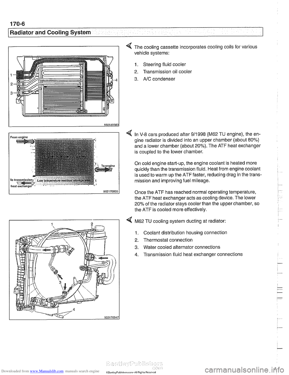
I I 4 The cooling cassette incorporates cooling coils for various
vehicle systems:
1. Steering fluid cooler
2. Transmission oil
coolel
3. AIC condenser
4 In V-8 cars produced after 911998 (M62 TU engine), the en-
gine radiator is divided into an upper chamber (about 80%)
and a lower chamber (about 20%). The ATF heat exchanger
is coupled to the lower chamber.
On cold engine start-up, the engine coolant is heated more
quicltly than the transmission fluid. Heat from engine coolant
is used to warm up the ATF faster, reducing drag in the trans-
mission and improving fuel mileage.
Once the ATF has reached normal operating temperature,
the ATF heat exchanger acts as cooling device. The lower
20% of the radiator
stays cooler than the upper chamber, so
the ATF is cooled more effectively.
4 M62 TU cooling system ducting at radiator:
1. Coolant distribution housing connection
2. Thermostat connection
3. Water cooled alternator connections
4. Transmission fluid heat exchanger connections
Page 503 of 1002

Downloaded from www.Manualslib.com manuals search engine
Warnings and cautions
Obse~e the following warnings and cautions when worlting
on the cooling system.
WARNING -
. At normal operating temperature the cooling system is
pressurized. Allow the system to cool as long as possible
before opening (a minimum of one hour), then release the
cap slowly to allow safe release ofpressure.
a Releasing the coolant system pressure lowers the cool-
ant boilingpoint and the coolant may boil suddenly. Use
1 heavy and wear eye and face protection to
guard against scalding.
Use extreme care when draining and disposing of en-
gine coolant. Coolant is poisonous and lethal to hu-
mans andpets. Pets are attracted to coolant because
of its sweet smell and taste. Seek medical attention im-
mediately if coolant is ingested.
CAUTIOG
Avoid adding cold water to the coolant while the engine is
hot or overheated. If it is necessary to add coolant to a
hol
system, do so only with the engine running and coolanl
pump turning.
To avoid excess silicate gel precipitation in the cooling
system and loss of cooling capacity, use BMW coolant
or equivalent low silicate antifreeze.
a If oil enters the cooling system, the radiator, expansion
tank and heating circuit must be flushed with cleaning
agent. BMW recommends removal of the radiator and
expansion
tank to flush.
When
worlcing on the cooling system, cover the alter-
nator to protect it against coolant drips.
Prior to disconnecting the battery, read the battery dis-
connection cautions given in
001 General Warnings
and Cautions.
Begin the diagnosis of cooling system problems with a thor-
ough visual inspection.
If no visual faults are found, it is rec-
ommend that the engine control module (ECM) fault memory
be checked for stored diagnostic trouble codes
(DTCs) using
BMW scan tool
DlSplus or equivalent.