Page 333 of 1002
![BMW 540i 1999 E39 Workshop Manual Downloaded from www.Manualslib.com manuals search engine
-- . - .. . - Lubrication system]
- Remainder of installation is reverse of removal.
Replace self-locking nuts when reinstalling front BMW 540i 1999 E39 Workshop Manual Downloaded from www.Manualslib.com manuals search engine
-- . - .. . - Lubrication system]
- Remainder of installation is reverse of removal.
Replace self-locking nuts when reinstalling front](/manual-img/1/2822/w960_2822-332.png)
Downloaded from www.Manualslib.com manuals search engine
-- . - .. . - Lubrication system]
- Remainder of installation is reverse of removal.
Replace self-locking nuts when reinstalling front suspen-
sion components.
Use new oil dipstick tube sealing O-ring.
After adding engine oil, start and run engine. Raise engine
speed to 2,500 rpm until oil pressure warning light goes out
(about 5 seconds).
NOTE-
BMW does not specify a front end alignment following this
procedure.
Tightening torques Front subfrarne to body rail
(M12, use new bolts)
8.8 grade
10.9 grade
12.9 grade 77 Nrn
(57 ft-lb)
105 Nrn (77 ft-lb)
110 Nrn (81 ft-lb)
Stabilizer bar link to stabilizer bar
65 Nrn (48 ft-lb)
Steering shaft universal joint clamping bolt
(use new bolt)
19 Nrn (14 it-lb)
Lower oil pan, removing and installing (V-8)
- The V-8 engine is equipped with a 2-piece oil pan. The fas-
teners in
V-8 engine oil pump assembly, including the
sprocket retaining nut, are known to loosen and fall off into
the oil pan. Be sure to install these fasteners with Loctite
O
or equivalent thread locking product and torque to specifica-
tions.
CAUTION-
It is recommended that the oil pump retaining bolts and oil
pump drive sprocket retaining nut tightening torque be
checkedany time the
oilpan is removed.
- Raise car and place securely on jack stands.
WARNING-
Make sure the car is stable and well supported at all times.
Use a professional automotive lift
orjack stands designed for
- Remove splash shield from under engine.
- Drain engine oil
- On cars with automatic transmission, remove ATF cooler line
brackets from oil pan.
Page 337 of 1002
Downloaded from www.Manualslib.com manuals search engine
1 19-1 7
Lubrication System
Disconnect electrical harness connect01
sensor.
. (arrow)
4 Remove lower oil pan bolts (arrows) and pan, oil
level
CAUTION-
If the lowerpan does not separate easily from upperpan, a
few taps with a rubber mallet should break it free. Do not pry
the oil pan loose.
Remove
NC drive belt tensioner.
Remove adjustment bolt
(B).
Remove retaining bolt (A) and remove tensioner from oil
pan.
- Remove power steering pump from engine block, leaving hy-
draulic lines connected. Suspend from chassis using stiff
wire. See
320 Steering and Wheel Alignment.
Page 338 of 1002
Downloaded from www.Manualslib.com manuals search engine
119-18
I Lubrication System
4 Working at lefl side of engine, remove oil dipstick guide tube 1 mounting bracket and remove dipstick tube.
NOTE-
Replace dipstick O-ring seal.
< Working at right side of engine, remove oil return line from
upper section of oil pan.
4 Separate lower steering column from steering box:
Remove retaining bolt
(arrow) from lower steering column
universal joint.
Slide lower steering column up and off of connection at
steering box.
- Remove support bracket for hydraulic line at subframe.
Page 340 of 1002
Downloaded from www.Manualslib.com manuals search engine
Lubr~cat~on System r- -
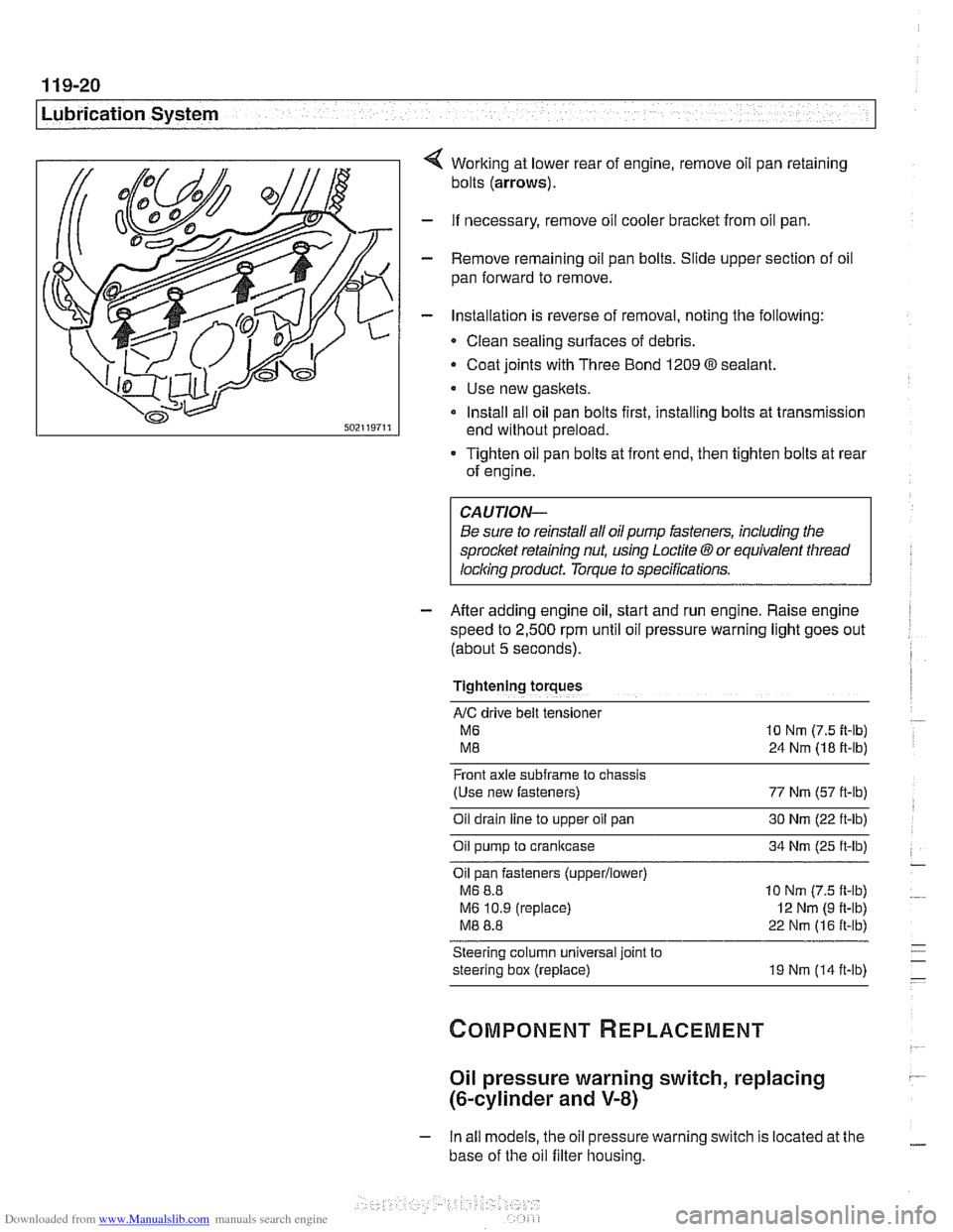
Working at lower rear of engine, remove oil pan retaining
bolts
(arrows).
- If necessary, remove oil cooler bracket from oil pan.
- Remove remaining oil pan bolts. Slide upper section of oil
pan forward to remove.
- Installation is reverse of removal, noting the following:
Clean sealing surfaces of debris.
- Coat joints with Three Bond 1209 O sealant.
Use new gaskets.
Install all oil pan bolts first, installing bolts at transmission
end without preload.
Tighten oil pan bolts at front end, then tighten bolts at rear
of engine.
Be sure to reinstall all oil
pump fasteners, including the
sprocl
- After adding engine oil, start and run engine. Raise engine
speed to
2,500 rpm until oil pressure warning light goes out
(about
5 seconds).
Tightening torques
AIC drive belt tensloner
M6 10 Nm (7.5 it-lb)
M8 24 Nm (18 ft-lb)
Front axle
subframe to chassis
(Use new fasteners) 77 Nm (57 ft-lb)
Oil drain
line to upper oil pan 30 Nm (22 ft-lb)
Oil pump to crankcase 34 Nm (25 ft-lb)
Oil pan fasteners
(upperllower)
M6 8.8 10 Nm (7.5 ft-lb)
M6 10.9 (replace)
I2 Nm (9 ft-lb)
M8 8.8 22 Nm (16 ft-lb)
Steering column universal joint to
steering box (replace) 19 Nm (14 ft-lb)
Oil pressure warning switch, replacing
(&cylinder and V-8)
- In all models, the oil pressure warning switch is located at the
base of the oil filter housing.
Page 381 of 1002
Downloaded from www.Manualslib.com manuals search engine
Battery, Starter, ~lternatorl
Alternator, removing and installing
(6-cylinder engine)
A replacement alternator should have the same rating as the
original. Alternator manufacturer and ampere rating are nor-
mally marked on the alternator housing.
- Disconnect negative (-) battery cable.
CAUTION-
Prior to disconnecting the batteg read the battery discon-
nection cautions given
in 001 General Warnings and Cau-
I tions.
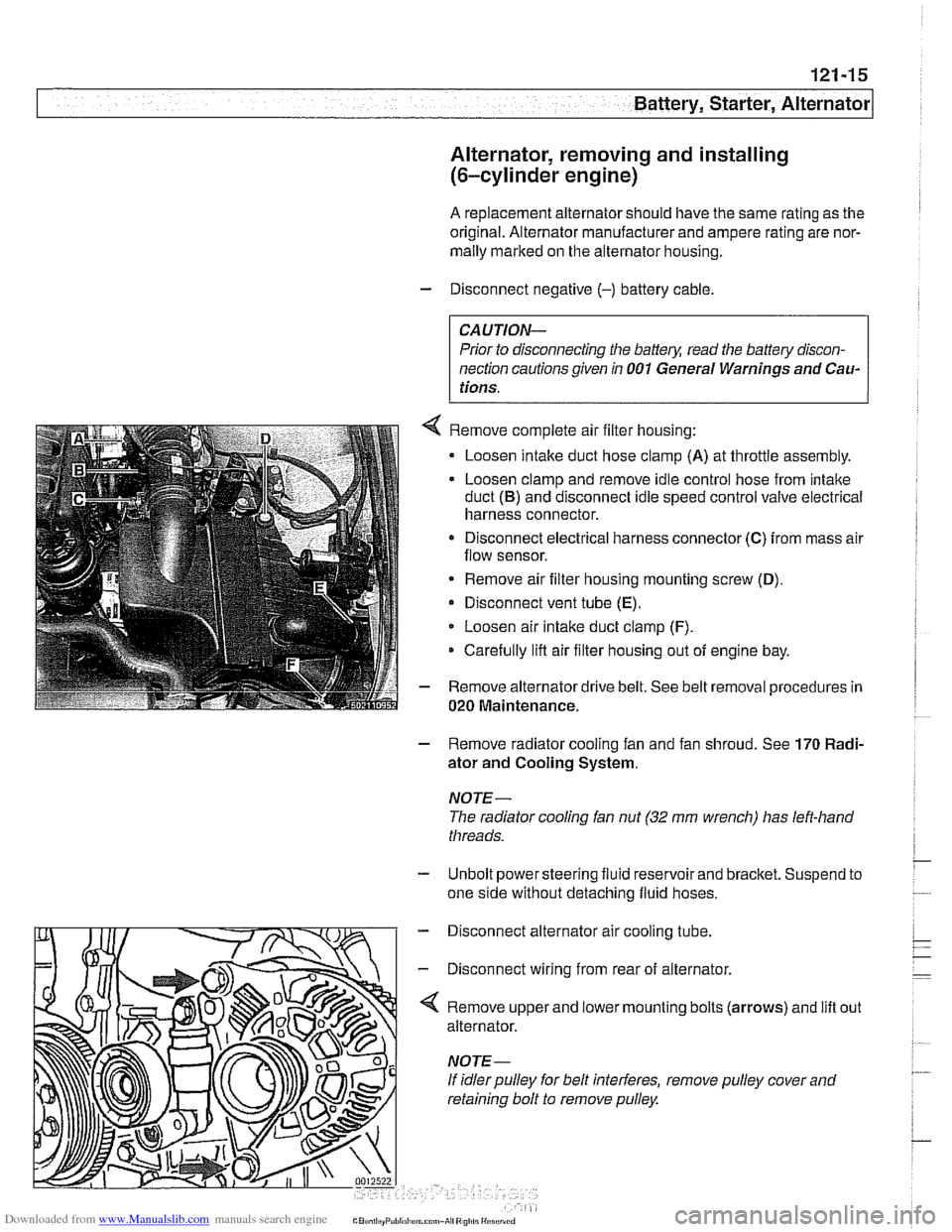
Remove complete air filter housing:
Loosen intake duct hose clamp
(A) at throttle assembly.
Loosen clamp and remove idle control hose from intake
duct
(B) and disconnect idle speed control valve electrical
harness connector.
Disconnect electrical harness connector
(C) from mass air
flow sensor.
* Remove air filter housing mounting screw (D),
Disconnect vent tube (E).
Loosen air intake duct clamp (F).
Carefully lifl air filter housing out of engine bay.
Remove alternator drive belt. See belt removal procedures in
020 Maintenance.
- Remove radiator cooling fan and fan shroud. See 170 Radi-
ator and Cooling System.
NOTE-
The radiator cooling fan nut (32 mm wrench) has left-hand
threads.
- Unbolt power steering fluid reservoir and bracket. Suspend to
one side without detaching fluid hoses.
- Disconnect alternator air cooling tube.
- Disconnect wiring from rear of alternator.
'4 Remove upper and lower mounting bolts (arrows) and lift
alternator.
If idler pulley for belt interferes, remove pulley cover and
retaining bolt to remove pulley. out
Page 469 of 1002
Downloaded from www.Manualslib.com manuals search engine
Fuel Injection I
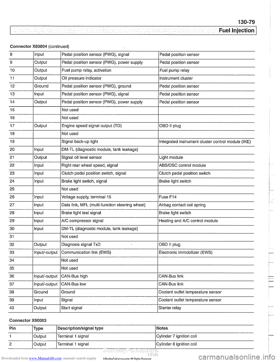
Connector X60004 (continued)
8 10
11
12
13
14
15
16
9
Output 0
Input
17
18
19
20
21
22
23
24
25
26
27
28
29
30
31
32
33
34
35
36
39
llnput lsignal l~oolant outlet temperature sensor
Output
Output
Ground
Input
Output
I I - I
40 /output Istart signal Istarter relay
Pedal position sensor (PWG), signal
Output Input
Output
input
Input
Input
Input
Input
Input
input
Input
Output
Input/-output
Input/-output
37
Connector X60003
Pedal position sensor
Fuel pump relay, activation
Oil pressure indicator Pedal position sensor (PWG), ground
Pedal position sensor (PWG), signal
Pedal position sensor (PWG), power supply
Not used
Not used Fuel
pump relay
Instrument cluster
Pedal position sensor
Pedal position sensor
Pedal position sensor
Engine speed signal output (TD)
Not used
Signal
back-up light
DM-TL (diagnostic module,
tank leakage)
Signal oil level sensor
Right rear wheel speed, signal
Clutch pedal position switch, signal
Brake light switch, signal
Not used
Voltage supply, terminal
15
Data link, MFL (multi-function steering wheel)
Brake light test signal
AJC compressor signal
DM-TL (diagnostic module, tank
leakage)
Not used
Diagnosis signal
TxD
Communication link (EWS)
Not used
Not used
CAN-BUS hiqh
38 1 Ground l~round I Coolant outlet temperature sensor
OED II plug
Integrated instrument cluster control module (IKE)
Light module
ABSIDSC control module
Clutch pedal position switch
Brake light switch
Fuse
F14
Airbag contact coil spring
Brake light switch
Heating and
A/C control module
OBD
II plug
Electronic immobilizer (EWS)
CAN-Bus link
CAN-Bus link
Input/-output CAN-Bus low
Page 502 of 1002
Downloaded from www.Manualslib.com manuals search engine
.. - -
I Radiator and Cooling System
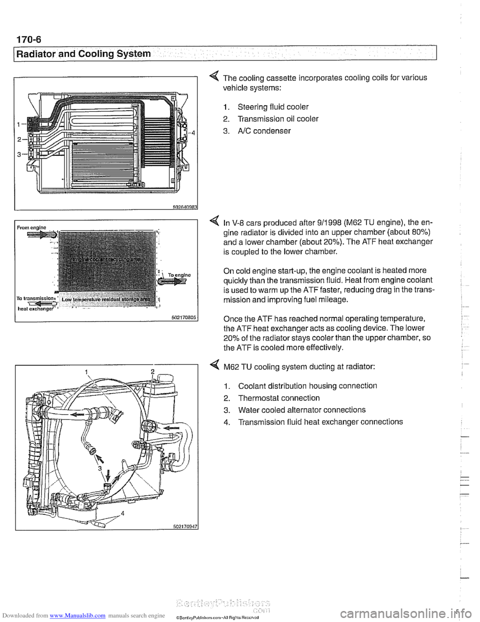
I I 4 The cooling cassette incorporates cooling coils for various
vehicle systems:
1. Steering fluid cooler
2. Transmission oil
coolel
3. AIC condenser
4 In V-8 cars produced after 911998 (M62 TU engine), the en-
gine radiator is divided into an upper chamber (about 80%)
and a lower chamber (about 20%). The ATF heat exchanger
is coupled to the lower chamber.
On cold engine start-up, the engine coolant is heated more
quicltly than the transmission fluid. Heat from engine coolant
is used to warm up the ATF faster, reducing drag in the trans-
mission and improving fuel mileage.
Once the ATF has reached normal operating temperature,
the ATF heat exchanger acts as cooling device. The lower
20% of the radiator
stays cooler than the upper chamber, so
the ATF is cooled more effectively.
4 M62 TU cooling system ducting at radiator:
1. Coolant distribution housing connection
2. Thermostat connection
3. Water cooled alternator connections
4. Transmission fluid heat exchanger connections
Page 530 of 1002
Downloaded from www.Manualslib.com manuals search engine
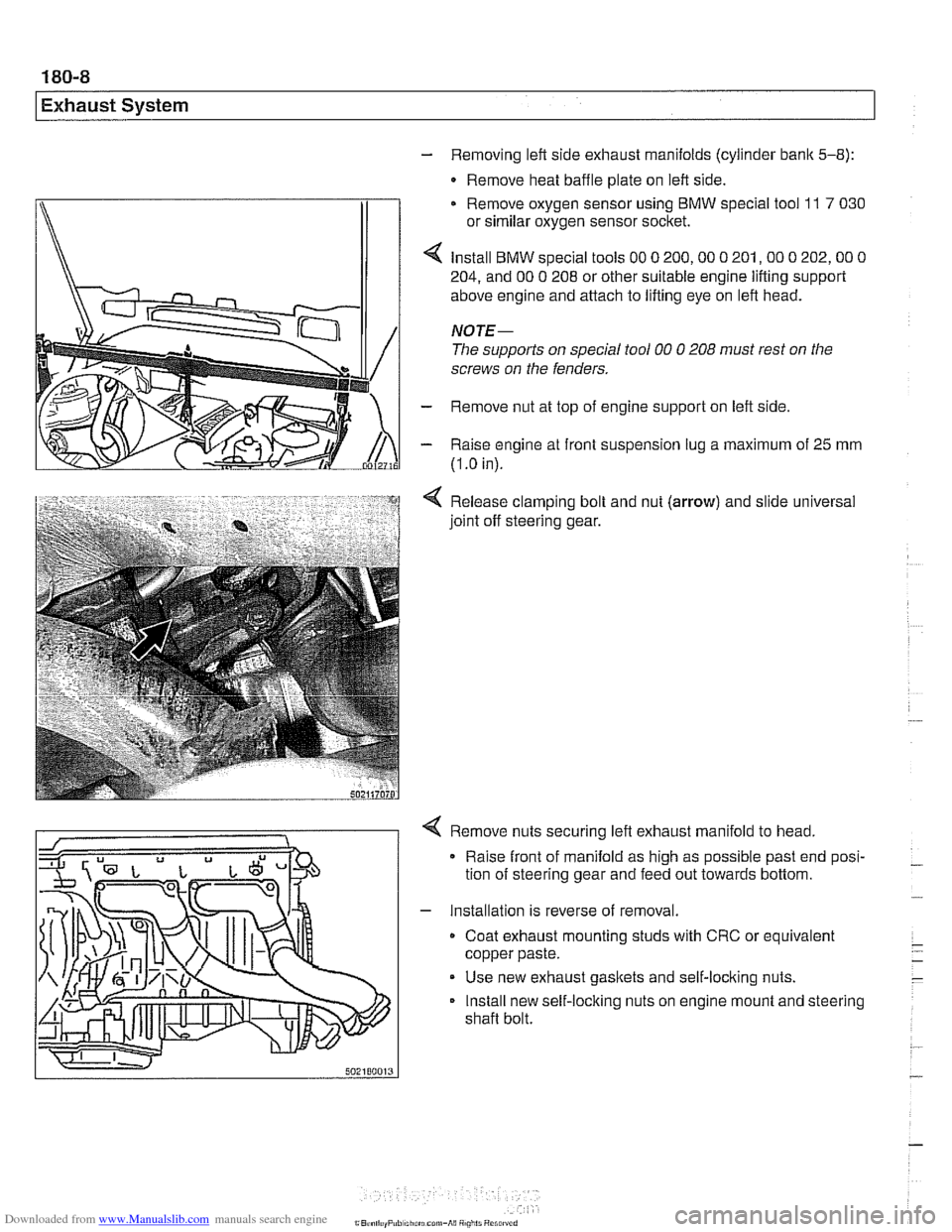
- Removing left side exhaust manifolds (cylinder bank 5-8):
- Remove heat baffle plate on left side.
Remove oxygen sensor using
BMW special tool 11 7 030
or similar oxygen sensor socket.
Install
BMW special tools 00 0 200,OO 0 201,OO 0 202,OO 0
204, and 00 0 208 or other suitable engine lifting support
above engine and attach to lifting eye on left head.
NOTE-
The supports on special tool 00 0 208 must rest on the
screws on the fenders.
- Remove nut at top of engine support on left side
- Raise engine at front suspension lug a maximum of 25 mm
(I
.O in).
Release clamping bolt and nut
(arrow) and slide universal
joint off steering gear.
4 Remove nuts securing left exhaust manifold to head,
Raise front of manifold as high as possible past end posi-
tion of steering gear and feed out towards bottom.
- Installation is reverse of removal.
Coat exhaust mounting studs with CRC or equivalent
copper paste.
Use new exhaust gaskets and self-locking nuts.
Install new self-locking nuts on engine mount and steering
shaft bolt.