1999 BMW 540i length
[x] Cancel search: lengthPage 579 of 1002

Downloaded from www.Manualslib.com manuals search engine
Manual Transmission
Input shaft seal, replacing
(transmission removed)
- Remove transmission from vehicle as described later in this
group.
- Remove clutch release bearing end release bearing lever
from inside bellhousing.
4 Remove bolts (arrows) for clutch release-bearing guide
sleeve, noting bolt lengths
(Getrag trensmission shown).
Remove sleeve and any spacers (shims) under it.
Two covered removal holes (arrows) are present in seal.
Thread BMW special tool
23 0 490 or equivalent slide ham-
mer seal puller into one hole and remove seal.
- Getreg S5D 250G transmission:
Place BMW special tool
23 2 460 or similar protective
sleeve over input shaft.
Coat sealing lip of new
seel with trensmission oil and push
over protective sleeve up to transmission housing.
Remove protective sleeve from input shaft.
Use BMW special tool
23 2 430 or similar drifl to drive seal
until fully seated.
- ZF S5D 3202 transmission:
Place BMW special tool
23 2 380 or similar protective
sleeve over input shaft.
Coat sealing lip of new seal with transmission oil and push
over protective sleeve up to transmission housing.
* Remove protective sleeve from input shaft.
Use BMW special tool
23 2 340 or similar drift to drive seal
until fully seated.
- 6-speed transmission:
Fit
cap of BMW special tool 23 2 492 over tool sleeve.
Coat sealing
lip of new seal with transmission oil and push
on tool sleeve. Remove tool cap from tool sleeve.
- Push sleeve with seal on input shaft.
- Use BMW special tool 23 2 491 or similar drift to drive seel
until fully seated.
Remove protective sleeve from input shaft.
Page 582 of 1002

Downloaded from www.Manualslib.com manuals search engine
230-1 8
Manual Transmission
- Unbolt clutch slave cylinder from side of transmission. Do not
disconnect fluid hose. Suspend slave cylinder from chassis
using stiff wire.
CA UTIOG
Unbolt clutch slave cylinder slowly to prevent air being
drawn into hydraulic system.
. Do not operate clutch pedal with slave cylinder re-
moved from transmission.
4 Put BMW special tool 11 7 370 or appropriate sized spacer
between engine oil sump and front axle support. Lower trans-
mission until engine is supported on spacer.
0 V-8 vehicle: Turn front wheels to prevent strain from being
placed on center tie rod.
All vehicles: Tilting the engine to lower the transmission
can lead to damage to various components due to lack
of clearance at rear of engine. Lower transmission
slowly
- Support front of engine with floor jack.
4 Disconnect shift rod from selector shaft coupling
- Disconnect shift console from top of transmission. See 250
Gearshift Linkage.
6-cylinder: Remove transrnisslon mounting Torx-head bolts
(arrows). Note length and locatlon of bolts.
Remove
transrnlssion by pulling backward untll transmls-
sion Input shaft clears clutch d~sc spl~nes, then pull down-
wards. Lower
transmlsslon jack to remove transrnlsslon. -
- - -
-
Page 583 of 1002

Downloaded from www.Manualslib.com manuals search engine
Manual Transmission
4 V-8 engine: Remove transmission mounting Tom-head bolts
(arrows). Note length and location of bolts.
Remove transmission by pulling backward until transmis-
sion input shaft clears clutch disc splines, then pull down-
wards. Lower transmission jack to remove transmission.
- Installation is reverse of removal, keeping in mind the
following:
When installing a new transmission, be sure to transfer
parts from old transmission
if applicable.
Thoroughly clean input shafl and clutch disc splines. Light-
ly lubricate transmission input shaft before installing.
* Be sure bellhousing alignment dowel sleeves are located
correctly. Replace damaged sleeves.
Center rear of transmission in driveshaft tunnel before
tightening transmission support bracket.
NOTE-
In order to avoid difficulties in transmission removal at a fu-
ture time, use washers with Torx-head mounting bolts.
- Reinstall driveshaft. Use new nuts when mounting driveshaff
to transmission/flex disc. See 260 Driveshaft.
- Refill transmission with appropriate lubricant before starting
or towing car. See Transmission fluid service earlier in this
repair group.
Page 690 of 1002

Downloaded from www.Manualslib.com manuals search engine
320-32
Steering and Wheel Alignment
Center tie
rod, replacing
- Raise front of car. Remove splash shield from under engine.
WARNING-
Make sure tlie car is firmly supported on jack stands de-
signed for the purpose. Place jack stands beneath structural
cliassis points. Do not place jack stands under suspension
parts.
- Measure length of left and right (outer) tie rods. Write down
measurements.
NOTE-
Accurate measurement of the tie rod end with reference to
the center tie rod will help approximate correct wheel align-
ment when new parts are installed.
4 Remove self-loclting nuts connecting center tie rod to pitman
and idler arms. Press tie rod off pitman and idler arms using
BMW special tool
32 1 190 or equivalent.
4 Loosen left tie rod clamping bolt (arrow). Unscrew left tie rod
from center tie rod. Repeat for right.
- Installation is reverse of removal.
Malte sure all threaded parts are clean.
. Coat threads with antiseize compound.
Replace self-loclting nuts.
Check tie rod end ball joints and idler arm bushing for wear.
Use tie rod measurements previously made to temporarily
set toe.
- Have car professionally aligned.
Tightening torques
Center tie rod to
pitman and idler arms 65 Nm (48 ft-lb)
(replace self-locking nuts)
Left or right outer
tie rod clamping bolt 27 Nm (20 it-lb)
Page 692 of 1002

Downloaded from www.Manualslib.com manuals search engine
320-34
I Steerins and Wheel Alignment
Front toe and toe difference angle
Toe is the difference in the distance between the front of the
front wheels and the rear of the front wheels. It is adjusted by
altering the length of the tie rods.
Toe difference angle determines the progressively different
paths taken by the front wheels as the car is turning. In
V-8
models, it is set by the pitman arm adjustment, but depends
on accurate setting of the toe.
Toe adjustments should only be made on specialized align-
ment equipment and only with the car in normal loaded posi-
tion, described below.
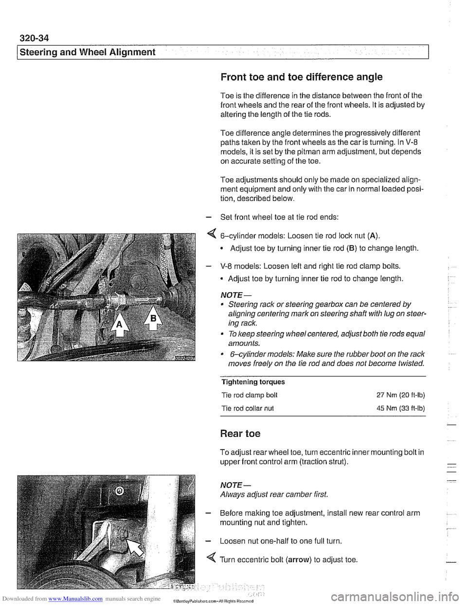
- Set front wheel toe at tie rod ends:
4 6-cylinder models: Loosen tie rod lock nut (A).
Adjust toe by turning inner tie rod (B) to change length
- V-8 models: Loosen left and right tie rod clamp bolts.
Adjust toe by turning inner tie rod to change length.
NOTE-
* Steering rack or steering gearbox can be centered by
aligning centering mark on steering shaft
with lug on steer-
ing rack.
To keep steering wheel centered, adjust both tie rods equal
amounts.
&cylinder models: Make sure the rubber boot on the rack
moves freely on the tie rod and does not become twisted.
Tightening torques
Tie rod clamp bolt
Tie rod collar
nut
27 Nm (20 ft-lb)
45 Nm (33 A-lb)
Rear toe
To adjust rear wheel toe, turn eccentric inner mounting bolt in
upper front control arm (traction strut).
NOTE-
Always adjust rear camber first.
- Before making toe adjustment, install new
mounting nut and tighten.
- Loosen nut one-half to one full turn.
4 Turn eccentric bolt (arrow) to adjust toe. rear
control arm
Page 703 of 1002

Downloaded from www.Manualslib.com manuals search engine
Rear ~us~ensionl
Rear strut assembly, disassembling and
assembling
Replace struts and coil springs in pairs only
Replacing the upper strut mount, spring or strut requires that
the strut assembly first be removed from the car, as described
earlier. Strut disassembly requires a spring compressor.
WARNING-
Do not attempt to disassemble the strut without a spring com-
pressor designed specifically for the job.
- Remove strut assembly from car as described in Rear strut
assembly, removing
bnd installing
4 Mount spring compressor (BMW special tools 31 3 340 and
31 3 350 or equivalent) in shop vice. Install correct-sized
spring retainers
(A).
WARNING-
Do not attempt to disassemble the struts without a spring
compressor designed specifically for this job.
* Prior to using the spring compressor checlc its opera-
tion. Do not use a spring compressor that is damaged.
Do not make any modifications to the spring compres-
sor.
Never use an impact wrench to compress or relieve
tension when using a spring compressor.
1
- Place strut assembly coil spring in spring retainers. Com-
press spring until force on upper strut mount is relieved.
Remove strut top mount self-locking nut with BMW special
tool
31 2 21 0 while counterholding strut shaft with a box end
wrench.
- Remove upper strut mount and related components. Sepa-
rate strut from spring.
NOTE-
Store the removed shock absorber upright Do not allow it to
lie horizontally or upside down for any length of time. If incor-
rect storage has occurred, place the
shoclc absorber upright
with the rod
fully extended for at least 24 hours.
- Replace strut, rubber bumper, upper strut mount or spring,
as needed.
NOTE- Relieve tension on spring compressor slowly and carefully.
Fit new spring in spring compressor so that one coil at
each end is outside spring retainer.
Page 817 of 1002

Downloaded from www.Manualslib.com manuals search engine
Fenders, Ensine HOO~I
Hood release cable and spring pins,
adjusting
Before adjusting hood pins, be sure the hood is aligned even-
ly to fenders and front panel.
- Malte sure bowden cable, which connects both hood loclts
together, is seated in lock guide on both left and right loclts.
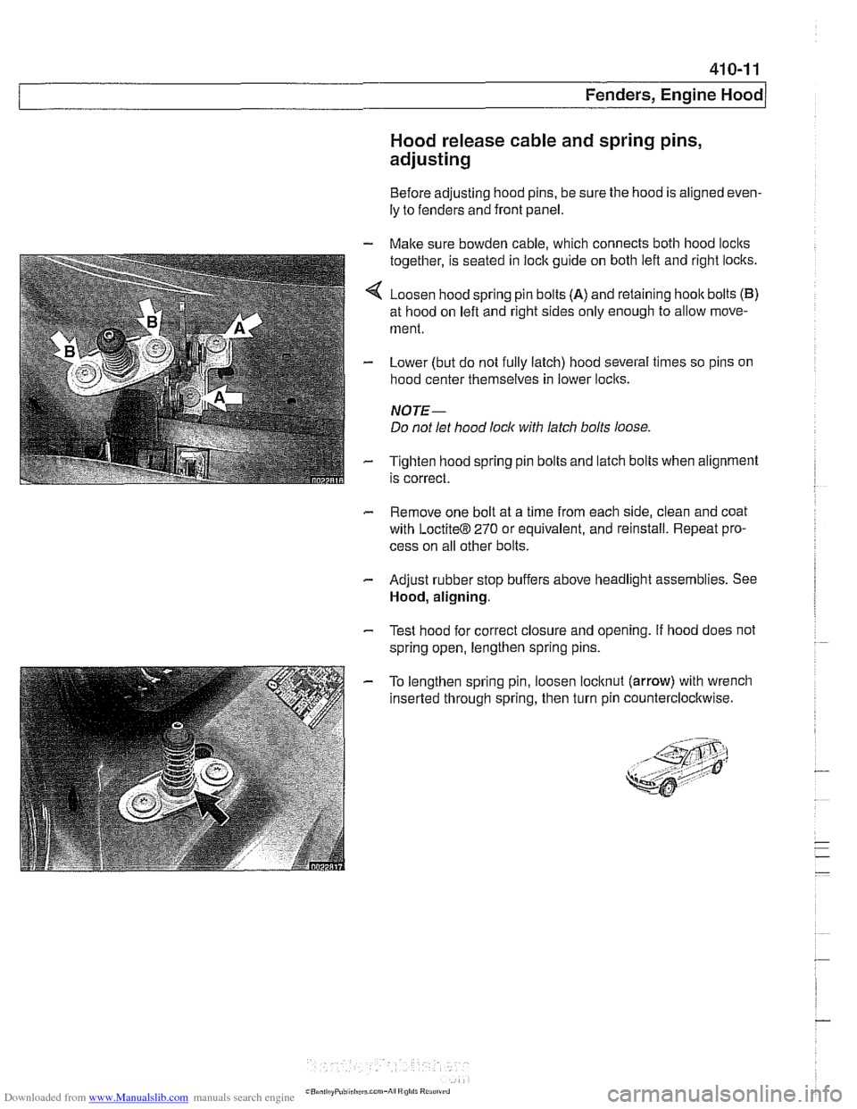
4 Loosen hood spring pin bolts (A) and retaining hoolt bolts (B)
at hood on left and right sides only enough to allow move-
ment.
- Lower (but do not fully latch) hood several times so pins on
hood center themselves in lower loclts.
NOTE-
Do not let hood lock with latch bolts loose
- Tighten hood spring pin bolts and latch bolts when alignment
is correct.
- Remove one bolt at a time from each side, clean and coat
with
LoctiteB 270 or equivalent, and reinstall. Repeat pro-
cess on all other bolts.
- Adjust rubber stop buffers above headlight assemblies. See
Hood, aligning.
- Test hood for correct closure and opening. If hood does not
spring open, lengthen spring pins.
- To lengthen spring pin, loosen locltnut (arrow) with wrench
inserted through spring, then turn pin counterclocltwise.
Page 846 of 1002

Downloaded from www.Manualslib.com manuals search engine
41 2-1 8
Trunk Lid, Tailgate
Tailgate gap and length adjustment
- Close tailgate and open rear window.
Loosen left and right tailgate hinge
bracket fasteners (ar-
rows)
to allow movement of tailgate.
CAUTION-
When the hinge bracket fasteners are loosened, the posi-
tion of the rear window frame changes with respect to the
tailgate.
Always
check the settings of the rear window frame to
the tailgate and
make adjustment if necessary
NOTE-
The tailgate should be approximately I mm lower then side
walls.
4 To obtain tailgate to body parallel alignment, top edge of tail-
gate must first be adjusted parallel to the edge
of D-pillar (A).
I D-pillar gap 27 rnrn (1.6 in)/
- Adjust gap with window open and tailgate closed.