1999 BMW 528i 100
[x] Cancel search: 100Page 755 of 1002

Downloaded from www.Manualslib.com manuals search engine
331-1 1
Final rive(
< Coat seal with differential oil and drive into place using BMW
special tools 00 5 500 and 33 4 250 or equivalent.
Replace snap ring (arrow) on final drive output flange shaft.
Coat output flange
shaft with differential oil where it con-
tacts shaft seal.
. Push output flange into final drive until flange splines en-
gage splines of differential gear and snap ring can be
heard to snap into place.
- Remainder of installation is reverse of removal.
Check and, if necessary, set differential oil level. See Dif-
ferential oil level, checking.
Tightening torques Drive axle to final drive flange
Torx bolts
(M10) 83 Nm (61 ft-lb)
Torx bolt with ribbed teeth (M10) 64 Nm (47 it-lb)
Torx bolt with ribbed teeth (Mi0 silver) 80 Nm (59 ft-lb)
Torx bolt with ribbed teeth (MI0 black) 100 Nm (74 ft-lb)
- Torx bolt with ribbed teeth (M12) 135 Nm (100 ft-lb)
Page 759 of 1002

Downloaded from www.Manualslib.com manuals search engine
Final ~rivel
4 Remove staked collar nut and press output shafl out of wheel
hub with special
BMW tool 33 2 111/116/117.
- Remove drive axle.
- Installation is reverse of removal, noting the following:
Use a new collar nut.
a Apply a light coating of oil to contact face of collar nut and
install it loosely.
* Install road wheel and lower car to ground.
- With an assistant applying brakes, tighten drive axle collar
nut to its final torque.
Stake collar nut.
Tightening torques
-
Drive axle collar nut to drive flange M27 300 Nrn (221 ft-lb)
Drive axle to differential flange
* M10x20 rnm black Torx bolt
83 Nrn (61 ft-lb)
M10x20 rnrn silver Torx bolt
100 Nrn (74 ft-lb)
Road wheel to hub 120 Nrn f 10 (89 ft-lbf7)
Drive axle, removing and installing
(Sport Wagon)
4 With an assistant applying brakes, brealc free staked collar
nut (arrow) at center of rear wheel hub. Do not remove com-
pletely.
NOJE-
The drive flange collar nut is tightened to a torque of over 300
Nm (221 ft-lb). Make sure the car is firmly on the ground.
WARNING -
Disable airsupply pump (if applicable) by disconnecting elec-
tricalplug before performing any repairs. Pump is located be-
neath a cover under the spare tire
in the floor of the cargo
compartment.
- Raise rear of car. Remove rear wheel.
WARNING -
Malce sure that the car is firmly supported on jack stands de-
signed for the purpose. Place the jack stands beneath struc-
tural chassis points. Do not place jack stands under
suspension parts.
- Models with rear coil springs: Remove cargo compartment
floor carpet.
Page 800 of 1002

Downloaded from www.Manualslib.com manuals search engine
.
I Body-General 1
Rear wiper system
The rear wiper assembly on the E39 Sport Wagon is a self-
contained unit. The control electronics are integrated into the
gear drive that is part of the motor assembly. The control elec-
tronics contain two hall sensors, one
forthe park position and
one
forthe end stop or to signal reverse direction of the wiper
motor.
-
Wiperlwasher
stalk switch
/ 4 - 3
502400100
4 The rear wiper is controlled through the stalk switch on the
steering column. The switch includes the following functions:
Intermittent rear window wiping
Programmed rear window wiping interval
Operation of rear window washer
The wiper system automatically controls the following safety
and convenience features:
* Wiper interrupted when rear glass is opened
Wiper interrupted if wiper arm is blocked
Continuous wiping when vehicle is shifled into reverse
Antenna and sound system
4 There are two diversity FM antenna amplifiers:
FMI amplifier located in the rear window frame
FM2 / FZV amplifier located in the lefl D-pillar
The radio amplifier and CD changer are behind the side
ac-
cess panels in the cargo compartment:
CD changer on lefl side
Sound system subwoofer on right side
The subwoofer has a hold down knob and is mounted on a
hinge. It can be swung out to access
the batteryand fuse pan-
el by unscrewing the knob.
Page 905 of 1002

Downloaded from www.Manualslib.com manuals search engine
515-11
Central Lockinq and ~nti-l heft/
4 The initialization procedure is as follows:
Close ail doors and have all keys available
2 LED Using lkey number I, turn ignition switch to KL R (ACCES-
SORY), then switch off within 5 seconds and remove first
key.
. - -- , ..-.---- - Within 30 seconds of turning ignition switch to OFF, press
and hold button
2.
1 While holding button 2, press and release (tap) button 1
three times within 10 seconds. Models to 1999: LED flash-
- If acknowledgement signal (doors lock / unlocking) does not
follow initialization procedure, repeat process. If ignition is
switched on during process, procedure is cancelled.
50251509‘1
NOTE-
The Key Memory function of the GM responds to the ley
identification number of each key If the keys are not initial-
ized
in the same orderprior to initialization, the ley memory
functions activated by the
l(eys will not be assigned correctly.
Always initialize the keys
in the same order.
es momentarily.
Release both buttons. GM immediately locks and unlocits
doors to signal successful initialization.
Remote system coding
* Initialize remaining lteys, repeating steps above.
The E39 remote entry system uses coded signals for security
purposes. The code signal sent by the transmitter is changed
every time the vehicle is lockedlunlocked with the transmitter.
A separate code signal is used for each transmitter that is ini-
tialized to the system. This allows for each transmitterto oper-
ate independently of the others.
Due to the changing of the code each time the buttons are de-
pressed, the system allows for a
lacit of synchronization be-
tween the transmitter and receiver. This would occur
if the
buttons on the transmitter are pressed inadvertently.
Up to
100 erroneous actuations of the transmitter are auto-
matically corrected
forby the control module. If more than 100
actuations are present, the operator need only to press the
button a second time to restore system operation.
Page 969 of 1002

Downloaded from www.Manualslib.com manuals search engine
On-Board Diagnostics
DIAGNOSTIC TROUBLE CODES
(DTCs)
Below is a listing of E39 powertrain (automatic transmission
and engine)
SAE P-codes, the corresponding BMW fault
codes, and the fault code definitions.
BMW fault codes expand on the SAE sanctioned DTCs and
are accessible primarily through the BMW diagnostic scan
tool or a BMW-specific scan tool.
l~utomatic transmission diagnostic trouble codes
P-code
IBMW-FC I DTC Definition
Ip0560 196 ISystem Voltage I
IPO~OO I129 l~eriai Communication Link I
1~0715 116 I InpuVTurbine Speed Sensor 'A' Circuit I
PO600
PO601
PO603
PO606
PO705
PO705
PO709
144
80
81
82
8
60
60
PO71 5
PO71 6
PO717
PO720
PO720
PO720
I I
PO721 159 loutput Speed Sensor Circuit RangeIPerformance I
Serial Communication Link
Internal Control Module Memory Check Sum Error
Internal Control Module Keep Alive Memory (KAM) Error
ECMIPCM Processor
Transmission Range Sensor 'A' Circuit Maliunction (PRNDL Input)
Transmission Range Sensor
'A' Circuit Malfunction (PRNDL input)
Transmission Range Sensor
'A' Circuit Intermittent
I I'
1~0722 132 IOutput Speed Sensor Circuit No Signal I
33
33
33
32
42
59
PO720
I I
PO727 1150 I Engine Speed Input Circuit No Signal
InpuVTurbine Speed Sensor 'A' Circuit
inpuVTurbine Speed Sensor 'A' Circuit RangeiPerformance
InpuVTurbine Speed Sensor 'A' Circuit No Signal
Output Speed Sensor Circuit
Output Speed Sensor Circuit
Out~ut Speed Sensor Circuit
PO720 1106 /output Speed Sensor Circuit
62
Output Speed Sensor Circuit
PO730
PO730
PO731
PO731
PO731 I I
100
102
50
51
100
PO731
incorrect Gear Ratio
Incorrect Gear Ratio
Gear 1 incorrect Ratio
Gear 1 incorrect Ratio
Gear 1 Incorrect Ratio
PO732 152 /Gear 2 Incorrect Ratio
131
Gear
1 Incorrect Ratio
Page 970 of 1002
Downloaded from www.Manualslib.com manuals search engine
On-Board Diagnostics
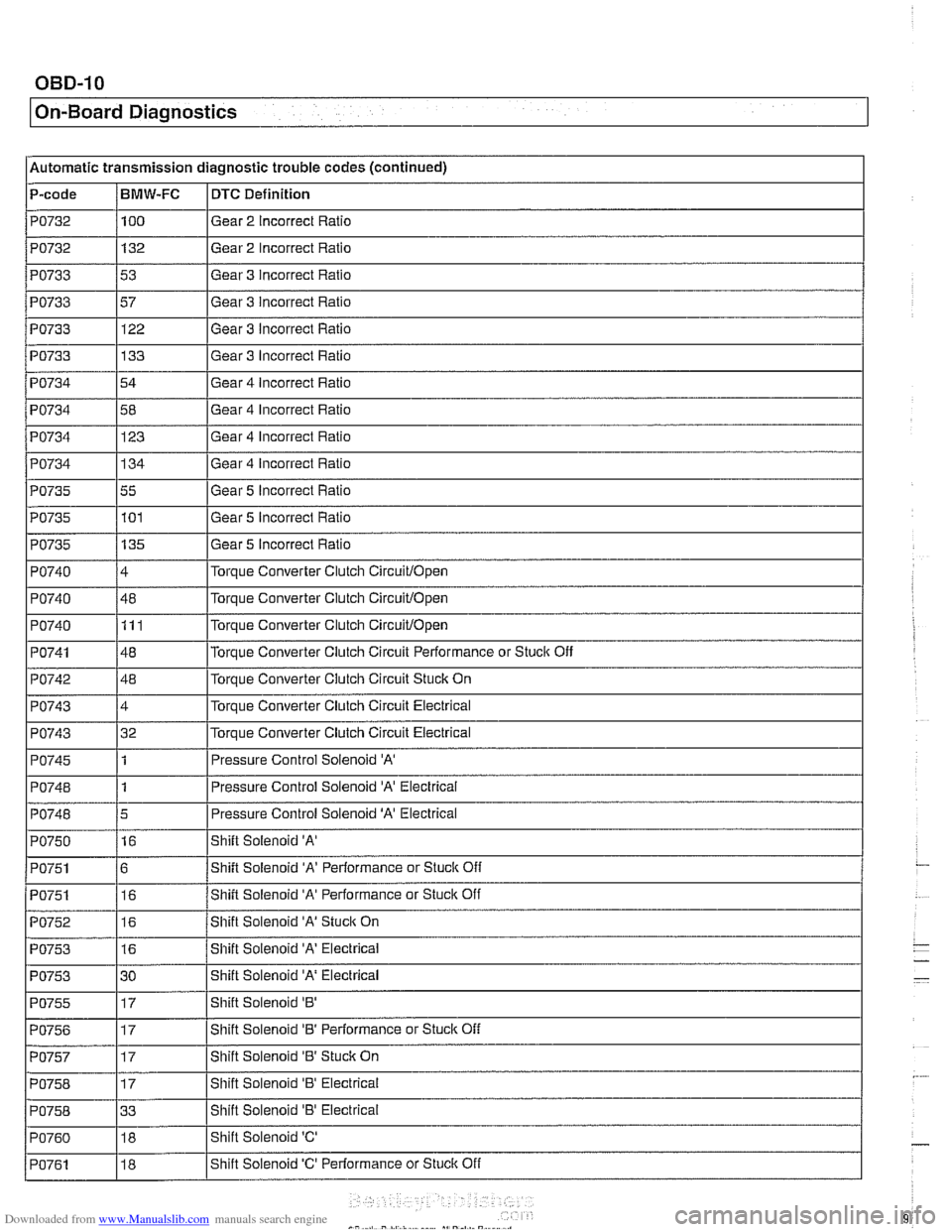
l~utornatic transmission diagnostic trouble codes (continued) -
P-code /BMW-FC I DTC Definition - PO732
PO732
PO733
PO733
PO733
PO733
PO734 -
I I
I I
PO742 / 48 l~orque Converter Clutch Circuit Stuck On
PO734
100
132
53
57 122
133
54
PO735
PO735
PO735
PO740
PO740
PO740
PO741
I I
PO743 14 l~or~ue Converter Clutch Circuit Electrical
Gear
2 Incorrect Ratio
Gear 2 Incorrect Ratio
Gear 3 incorrect Ratio
Gear 3 Incorrect Ratio
Gear 3 Incorrect Ratio
Gear 3 Incorrect Ratio
Gear 4 Incorrect Ratio
Gear
4 Incorrect Rat10 PO734
I I
PO743 132 l~or~ue Converter Clutch Circuit Electrical
PO734 1134 IGear 4 Incorrect Ratio
123
55 101
135
4
48 111
48 Gear 5 Incorrect Ratio
Gear 5
Incorrect Ratio
Gear 5 Incorrect Ratio
Torque Converter Clutch
Circuitlopen
Torque Converter Clutch Circuitlopen
Torque Converter Clutch Circuitlopen
Torque Converter Clutch Circuit Performance or Stuclc Off
PO745
PO748
PO748
PO750
PO751
PO751
I I
PO755 117 IShift Solenoid '8' I
PO752
PO753
PO753
PO756 117 I~hift Solenoid '8' Performance or Stuck Off I
1
1
5
16
6 16 Pressure Control Solenoid 'A'
Pressure Control Solenoid 'A' Electrical
Pressure Control Solenoid
'A' Electrical
Shift Solenoid
'A'
Shift Solenoid 'A' Performance or Stuck Off
Shift Solenoid
'A' Performance or Stuck Off
16
16
30 Shift
Solenoid
'A' Stuck On
Shift Solenoid 'A' Electrical
Shift Solenoid
'A' Electrical
PO757
PO758
PO758
PO760
PO761
17
17
33 18
18 Shift
Solenoid '8' Stuclc On
Shift Solenoid
'8' Electrical
Shift Solenoid
'8' Electrical
Shift Solenoid
'C'
Shift Solenoid 'C' Performance or Stuclc Off
Page 975 of 1002

Downloaded from www.Manualslib.com manuals search engine
OBD-15
On-Board ~iagnosticsl
Engine diagnostic trouble codes: M52 engine (continued)
P-code
PO340
PO412
PO420
PO430
PO440
PO441
PO442
PO443
PO500
PO505
PO600
PO601
PO601
I PO601
~1132
~1133
BMW-FC
65
62
233
234
250 144
-
145
68
214
i I
DTC Definition
Camshalt Position Sensor 'A' Circuit (Bank 1 or Single Sensor)
Secondary Air Injection System Switching Valve A Circuit
Catalyst System Efficiency Below Threshold
(Bank 1)
Catalyst System Efficiency Below Threshold (Bank 2)
Evaporative Emission System
Eva~orative Emission Svstem Incorrect Purge Flow .
Evaporative Emission System Leak Detected (small leak)
Evaporative Emission System Purge Control Valve Circuit
Vehicle Speed Sensor 'A'
204
21 7
100
170
171
188
189
PI161
PI180
PI181
PI184
PI185
PI178
02 Sensor Heater Control Circuit (Bank 2 Sensor 2) I
idle Air Control System
Serial Communication
Link
Internal Control Module Memory Check Sum Error
Internal Control Module Memory
Check Sum Error
Internal Control Module Memory
Check Sum Error
02 Sensor Heater Control Circuit (Bank 1 Sensor
1)
02 Sensor Heater Control Circuit (Bank 2 Sensor 1)
Mass or Volume Air Flow Circuit RangeIPerlormance Problem PI140
I
I I
P1188 1227 I Fuel Control (Bank 1 Sensor 1)
PI145 150 /Solenoid Valve Running Losses Control Circuit Electrical
149
122
223
224
220 221
231
I I
P1189 1228 I Fuel Control (Banlc 2 Sensor 1)
Fuel Trim Adaptation Additive High (Bank 2) (M52: Engine Oil Temperature Sensor Circuit)
02 Sensor Signal Circuit Slow Switching from Rich to Lean
(Bank 1 Sensor 2)
02 Sensor Signal Circuit Slow Switching from Rich to Lean
(Bank 2 Sensor 2)
H02S Sensor Voltage Excursion Electrical (Banlc 1 Sensor 1)
HO2S Sensor Voltage Excursion Electrical (Banlc 2 Sensor 1)
02 Sensor Sianai Circuit Slow Switchina from Rich to Lean (Bank 1 Sensor 1)
02 Sensor Signal Circuit Slow Switching from Rich to Lean (Bank 2 Sensor 1) PI179
I I
PI190 1235 I Pre Catalyst Fuel Trim System (Banlc 1)
PI186 1190 102 Sensor Heater Control Circuit (Banlc 1 Sensor 2)
232
I I
PI191 1236 I Pre
Catalyst Fuel Trim System (Banlc 2)
PI192
. . -- - i Pi193 1226 I Post Catalvst Fuel Trim Svstem (Bank 2)
225
PI397
I I
Post Catalyst Fuel Trim System (Bank 1)
PI421 1246 /Secondarv Air System (Bank 2)
18
Secondary Air System (Bank
1) PI423
Camshaft Position Sensor '0' Circuit (Bank 1)
I 245
Page 980 of 1002
Downloaded from www.Manualslib.com manuals search engine
I On-Board Diagnostics
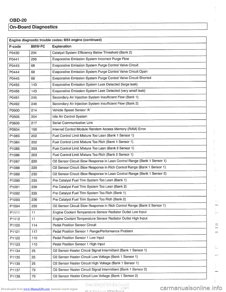
Engine diagnostic trouble codes: M54 engine (continued)
P-code
BMW-FC Explanation
Catalyst System Efficiency Below Threshold (Bank 2)
PO430
PO443
PO444
PO445
PO455
PO456
PO491
PO492
PO500
PO441 1250 / Evaporative Emission System Incorrect Purge Flow
234
I I
68
68
68 143
143
245
246
214
PO604
PI083
PI084
PI085
PI086
Evaporative Emission System Purge Control Valve Circuit
Evaporative Emission System Purge Control Valve Circuit Open
Evaporative Emission System Purge Control Valve Circuit Shorted
Evaporative Emission System Leak Detected (large leak)
Evaporative Emission System Leak Detected (very
small leak)
Secondary Air injection System Insufficient Flow (Bani( 1)
Secondary Air Injection System insufficient Flow
(Banic 2)
Vehicle Speed Sensor
'A'
Idle Air Control System PO505
.
PI 087
PI 088
PI089
PI090
PO600 / 217 I Serial Communication Link
204
100
202
202
203
203
PI091
PI092
PI093
PI094
Pllll
PI112
PI120
Internal Control Module Random Access Memory (RAM) Error
Fuel Control Limit Mixture Too Lean (Bank 1 Sensor
1)
Fuel Control Limit Mixture Too Rich (Bank 1 Sensor 1)
Fuel Control Limit Mixture Too Lean (Bank 2 Sensor 1)
Fuel Control Limit Mixture Too Rich (Banic 2 Sensor 1) ~ ~
229
229
230 235
PI121
PI122
PI123
02 Sensor Circuit Slow Response in Lean Control Range (Bank 1 Sensor 1)
02 Sensor Circuit Slow Response in Rich Control Range (Bank 1 Sensor
1)
02 Sensor Circuit Slow Response in Lean Control Range (Banlc 1 Sensor 2)
Pre Catalyst Fuel Trim System Too Lean
(Bank 1)
236
235
236
230
11
11
114
PI134
PI135
PI136
PI137
PI138
Pre Catalyst Fuel Trim System Too Lean (Banic 2)
Pre Catalyst Fuel Trim System Too Rich
(Bank 1)
Pre Catalyst Fuel Trim System Too Rich (Bank 2)
02 Sensor Circuit Slow Response in Rich Control Range (Banic 2 Sensor 1)
Engine Coolant Temperature Sensor Radiator Outlet Low Input
Engine Coolant Temperature Sensor Radiator Outlet High Input
Pedal Position Sensor Circuit
117
110
110
25
25
25
79
79 Pedal Position Sensor 1
RangeIPerformance Problem
Pedal Position Sensor 1 Low Input
Pedal Position Sensor 1 High Input
02 Sensor Heater Circuit Signal Intermittent (Bank 1 Sensor 1)
02 Sensor Heater Circuit Low Voltage (Bank 1 Sensor
1)
02 Sensor Heater Circuit High Voltage (Bank 1 Sensor 1)
02 Sensor Heater Circuit Signal Intermittent (Bank 1 Sensor 2)
02 Sensor Heater Circuit Low Voltage
(Banic 1 Sensor 2)
-
-