Page 529 of 1002

Downloaded from www.Manualslib.com manuals search engine
1 Exhaust ~vsteml
NOTE-
The front exhaust manifold must be removed before the rear
manifold.
- Installation is reverse of removal.
Coat exhaust mounting studs with CRC or equivalent cop-
per paste.
Use new gasltets and self-locking nuts.
Tightening torques Exhaust manifold to cylinder head 20 Nm
(15 ft-lb)
Front exhaust pipe to manifold 30 Nm
(22 ft-lb)
Oxygen sensor to manifold 50
Nrn (37 ft-lb)
Exhaust manifolds, removing and installing
(M62 engine)
Always use new retaining nuts and gasltets when removing
and installing the exhaust manifolds.
NOTE-
Access to manifolds is extremely limited. If removing exhaust
manifolds as part of additional engine worlc (such as cylinder
head removal), it may be easier to first remove engine.
- With exhaust system cold, raise and support car for access
to exhaust system.
WARNING -
Do not work undera lifted car unless it is solidly supported on
jaclt stands designed for the purpose. Never worlc undera car
that is supportedsolely
by a jack.
- Remove exhaust system. See Exhaust system, removing
and installing.
- Removing right side exhaust manifolds (cylinder bank 1-4):
Remove heat baffle plate.
Disconnect plug connection to oxygen sensor.
securing exhaust manifolds to head.
Remove manifolds towards bottom.
- Installation is the reverse of removal.
Coat exhaust mounting studs with CRC or equivalent
copper paste.
Use new gasltets and self-loclting nuts.
Page 530 of 1002

Downloaded from www.Manualslib.com manuals search engine
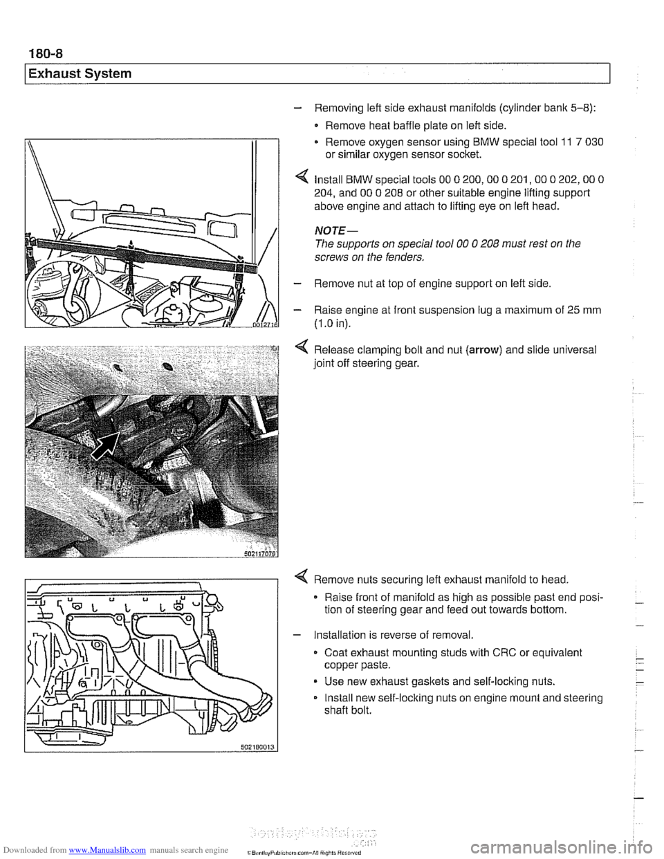
- Removing left side exhaust manifolds (cylinder bank 5-8):
- Remove heat baffle plate on left side.
Remove oxygen sensor using
BMW special tool 11 7 030
or similar oxygen sensor socket.
Install
BMW special tools 00 0 200,OO 0 201,OO 0 202,OO 0
204, and 00 0 208 or other suitable engine lifting support
above engine and attach to lifting eye on left head.
NOTE-
The supports on special tool 00 0 208 must rest on the
screws on the fenders.
- Remove nut at top of engine support on left side
- Raise engine at front suspension lug a maximum of 25 mm
(I
.O in).
Release clamping bolt and nut
(arrow) and slide universal
joint off steering gear.
4 Remove nuts securing left exhaust manifold to head,
Raise front of manifold as high as possible past end posi-
tion of steering gear and feed out towards bottom.
- Installation is reverse of removal.
Coat exhaust mounting studs with CRC or equivalent
copper paste.
Use new exhaust gaskets and self-locking nuts.
Install new self-locking nuts on engine mount and steering
shaft bolt.
Page 531 of 1002

Downloaded from www.Manualslib.com manuals search engine
-- -
Exhaust System
Oxygen sensors (precatalyst), replacing
(M52 TU and M54)
The precatalyst oxygen sensors are installed at the top of the
exhaust manifolds.
WARNING-
Allow components to cool before servicing.
- Using BMW scan tool DlSplus (Diagnostic Information Sys-
tem) or equivalent, read out and clear ECM fault codes.
Working at right side of engine above exhaust manifolds,
remove front or rear oxygen sensor harness connector
(arrows) from bracket, then separate plug.
NOTE-
In photo, secondary air pump has been removed for clarity.
Remove oxygen sensor using special oxygen sensor
removal socket.
Installation is reverse of removal
New sensor threads come coated with anti-seize paste.
If reusing a sensor, apply thin coat of anti-seize paste to
threads only. Do not contaminate tip of sensor with paste
or lubricants of any sort.
Install harness and connector in original location.
Tightening torque
- -.
Oxygen sensor to manifold 50 Nm (37 ft-lb)
Oxygen sensors (post-catalyst), replacing
(M52 TU and M54)
The post-catalyst oxygen sensors are installed at the rear of
the catalytic converters.
WARNING-
Allow components to cool before servicing
- Using BMW scan tool DlSplus or equivalent, read out and
clear ECM fault codes.
- Remove large cover from above fuel raillintake manifold.
Page 532 of 1002

Downloaded from www.Manualslib.com manuals search engine
Exhaust System
Label and disconnect sensor harness connectors (arrows).
CAUTlOI\C
Label connectors so that front and rear connectors are not
mixed up.
- Detach harness from guides and brackets.
- Remove oxygen sensor from exhaust manifold using special
tool
11 7 030 or equivalent.
- Installation is reverse of removal
New sensor threads come coated with anti-seize paste.
If reusing old sensor, apply thin coat of anti-seize paste to
threads only. Do not contaminate tip of sensor with paste
or lubricants of any sort.
Install harness and connector in original location.
Tightening torque
Oxygen sensor to manifold 50 Nm (37 ft-lb)
Oxygen sensor, replacing
(M52 and M62 engine)
The sensors are installed at the front and rear of the catalytic
converters.
I WARNING- I
I Allow components to cool before servicing. I
Using BMW scan tool DlSplus or equivalent, read out and
clear
ECM fault codes.
Detach harness from guides and brackets.
Remove oxygen sensors (arrows) from exhaust using spe-
cial tool
ll 7 030 or equivalent.
Installation is reverse of removal
New sensor threads come coated with anti-seize paste.
If reusing a sensor, apply thin coat of anti-seize paste to
threads only. Do not contaminate tip of sensor with paste
or lubricants of any sort.
Install harness and connector in original location.
Tightening torque
Oxvaen sensor to manifold 50 Nm (37 it-lb)
Page 550 of 1002

Downloaded from www.Manualslib.com manuals search engine
21 0-8
Clutch
4 Remove hydraulic line locking clip (1) and pull line (2) off
master cylinder.
CAUTION-
. To prevent brake fluidspill, wrap clutch master cylinder with
shop rags when removing hydraulic fluid lines from master
cylinder.
* Brake fluid damages paint andstains carpets. Clean off
any brake fluid on or
in the car immediately.
- Remove master cylinder with supply hose
4 Remove switch module from master cylinder.
Press locking button
(A) to release harness connector.
Pull harness connector
(8) off switch module.
Use screwdriver to lever
off switch module (C).
- Installation is reverse of removal.
CA UTlON-
Switch module must snap firmly into place on the master cyl-
inder during installation.
Tightening torques
Clutch master cylinder to pedal cluster
10 Nm (89 in-lb)
Fluid line
to master cylinder or slave cylinder 17 Nm (13 ft-lb)
- Fill fluid reservoir with clean fluid. Bleed clutch hydraulics as
described earlier.
Clutch slave cylinder, replacing
4 Working inside engine compartment, remove left interiorven-
tilation filter housing:
Release
3 plastic taps (A) on duct. Early models: release
latch.
Rotate duct inward to remove.
Disconnect electrical harness to hood position switch.
Release spring lock (B) on interior ventilation housing and
remove housing.
- Pinch off brake fluid supply hose to clutch master cylinder us-
ing BMW special tool
13 3 01 0 or equivalent hose clamping
tool.
Page 551 of 1002

Downloaded from www.Manualslib.com manuals search engine
- Raise and safely support vehicle
WARNING-
Make sure the car is stable and well supporied at all times.
Use a professional automotive /iff orjack stands designed for
the
ournose. A floor jack is not adeouate suooort.
- If necessary, remove transmission splash shield.
- Disconnect fluid line from slave cylinder on lefl side of trans-
mission. Place pan under hose to catch dripping fluid.
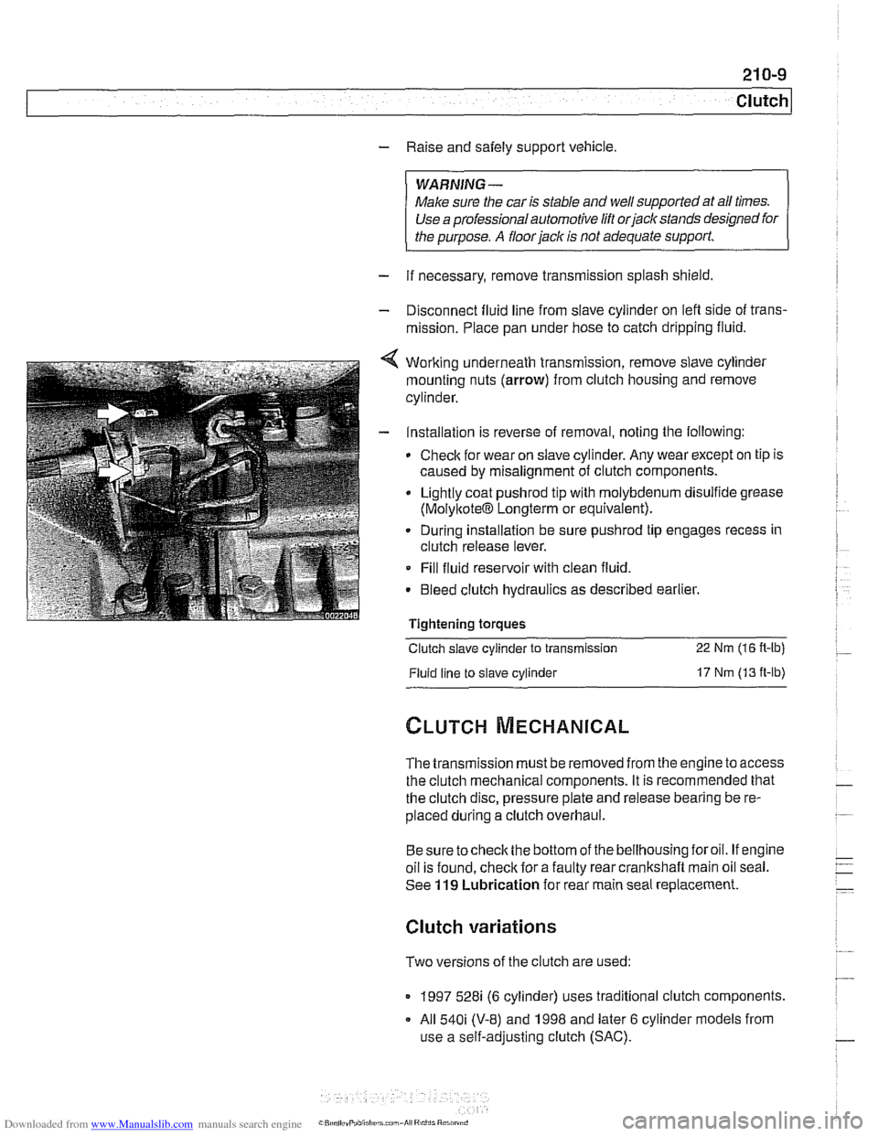
4 Working underneath transmission, remove slave cylinder
mounting nuts (arrow) from clutch housing and remove
cylinder.
- Installation is reverse of removal, noting the following:
Check for wear on slave cylinder. Any wear except on tip is
caused by misalignment of clutch components.
Lightly coat
pushrod tip with molybdenum disulfide grease
(MolyltoteIB Longterm or equivalent).
. During installation be sure pushrod tip engages recess in
clutch release lever.
Fill fluid reservoir with clean fluid.
. Bleed clutch hydraulics as described earlier.
Tightening
toraues - -.
Clutch slave cylinder to transmission 22 Nm (16 R-lb)
Fluid line to slave cylinder 17 Nm (13 ft-lb)
The transmission must be removed from the engine to access
the clutch mechanical components. It is recommended that
the clutch disc, pressure plate and release bearing be re-
placed during a clutch overhaul.
Besure tocheck the bottom of the bellhousing foroil. If engine
oil is found, check for a faulty rear crankshaft main oil seal.
See
119 Lubrication for rear main seal replacement.
Clutch variations
Two versions of the clutch are used:
1997 528i (6 cylinder) uses traditional clutch components.
All
540i (V-8) and 1998 and later 6 cylinder models from
use a self-adjusting clutch (SAC).
Page 569 of 1002
Downloaded from www.Manualslib.com manuals search engine
230-5
Manual Transmission
Manual transmission applications
Manual transmissions used are based on engine application.
See Table a. Manual transmission applications. For gear
ratio specifications,
seeTable b. Manual transmission gear
ratios.
Table a. Manual transmission applications
Model Year Engine Transmission
5251
Sedan 2001 -2002 M54 Getrag S5D 250G
Sport Wagon 2001-2002
M54 ZF S5D 3202
5281 all 1997-2000 M52, M52 TU ZF S5D 3202
530i Sedan 2001
-2002 M54 ZF
S5D 3202
540i Sedan
1997-2002 M62, M62 TU ZF S6S 420G
NOTE-
Do not rely on casting numbers for transmission code
identification.
Table b. Manual transmission gear ratios
-
Getrag Gear Getrag S5D 250G ZF S5D 3202 S6S 420G 5-speed 5-speed 6-speed
6 th 0.83
Reverse 4.04 3.89 3.75
Final drive 3.15
523: 3.23 2.81
5281 530i: 2.93
Page 573 of 1002

Downloaded from www.Manualslib.com manuals search engine
230-9
Manual ~ransmissionl
Carefully pry out selector shaft oil seal with BMW special tool
23
0 210, or with a narrow seal remover or small screwdriver.
Coat new selector shaft seal with transmission fluid. Drive
new seal in flush with housing. Use
BMW special seal instal-
lation tool
23 0 220 or equivalent and a soft-faced (plastic)
hammer.
- Remainder of installation is reverse of removal, noting the fol-
lowing:
Install driveshaft using new
loclc nuts.
Check transmission oil level, topping up as necessary.
Tightening torques Aluminum driveshaft to flex-disc
. MI2 (use Dacromet-coated washers) 90 Nm (66 ft-lb)
Driveshaft CV joint to final drive flange
MI 0 (Torx bolt) 70
Nm (51 ft-lb)
M8 (compression nut) 32
Nm (24 ft-lb)
Flex-disc to transmission flange or driveshaft
MI0 (8.8 grade) 48 Nm (35 ft-lb)
MI0 (10.9 grade) 60
Nm (44 it-lb)
MI2 (8.8 grade) 81
Nm (60 ft-lb)
MI2 (10.9 grade) lo0 Nm (74 ft-lb)
- MI4 140 Nm (103 ft-lb)
Transmission crossmember
to transmission (ME) 21 Nm (15 ft-lb)
. to chassis (M10) 42 Nm (30 ft-lb)