Page 529 of 1002

Downloaded from www.Manualslib.com manuals search engine
1 Exhaust ~vsteml
NOTE-
The front exhaust manifold must be removed before the rear
manifold.
- Installation is reverse of removal.
Coat exhaust mounting studs with CRC or equivalent cop-
per paste.
Use new gasltets and self-locking nuts.
Tightening torques Exhaust manifold to cylinder head 20 Nm
(15 ft-lb)
Front exhaust pipe to manifold 30 Nm
(22 ft-lb)
Oxygen sensor to manifold 50
Nrn (37 ft-lb)
Exhaust manifolds, removing and installing
(M62 engine)
Always use new retaining nuts and gasltets when removing
and installing the exhaust manifolds.
NOTE-
Access to manifolds is extremely limited. If removing exhaust
manifolds as part of additional engine worlc (such as cylinder
head removal), it may be easier to first remove engine.
- With exhaust system cold, raise and support car for access
to exhaust system.
WARNING -
Do not work undera lifted car unless it is solidly supported on
jaclt stands designed for the purpose. Never worlc undera car
that is supportedsolely
by a jack.
- Remove exhaust system. See Exhaust system, removing
and installing.
- Removing right side exhaust manifolds (cylinder bank 1-4):
Remove heat baffle plate.
Disconnect plug connection to oxygen sensor.
securing exhaust manifolds to head.
Remove manifolds towards bottom.
- Installation is the reverse of removal.
Coat exhaust mounting studs with CRC or equivalent
copper paste.
Use new gasltets and self-loclting nuts.
Page 530 of 1002

Downloaded from www.Manualslib.com manuals search engine
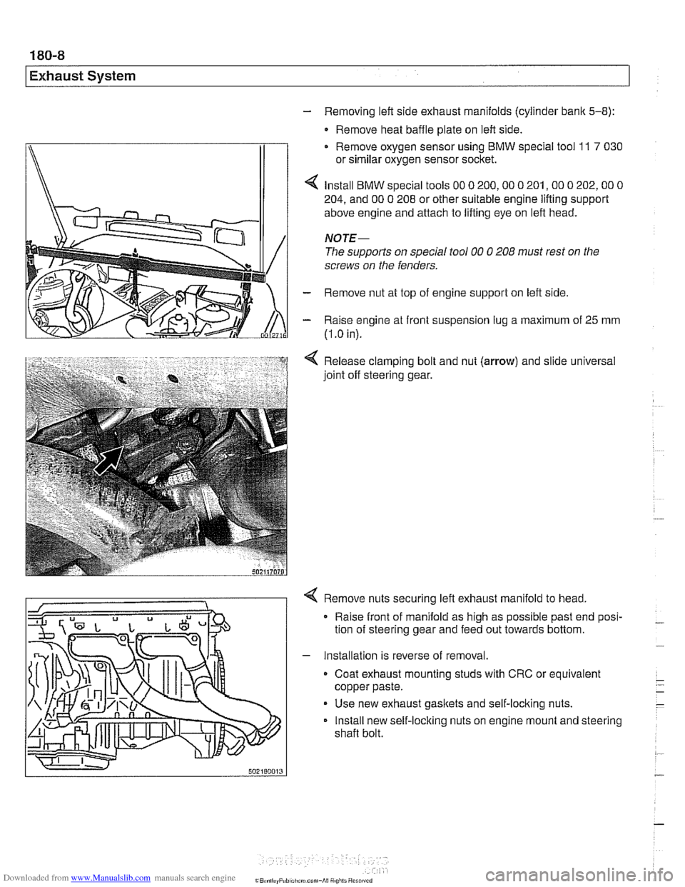
- Removing left side exhaust manifolds (cylinder bank 5-8):
- Remove heat baffle plate on left side.
Remove oxygen sensor using
BMW special tool 11 7 030
or similar oxygen sensor socket.
Install
BMW special tools 00 0 200,OO 0 201,OO 0 202,OO 0
204, and 00 0 208 or other suitable engine lifting support
above engine and attach to lifting eye on left head.
NOTE-
The supports on special tool 00 0 208 must rest on the
screws on the fenders.
- Remove nut at top of engine support on left side
- Raise engine at front suspension lug a maximum of 25 mm
(I
.O in).
Release clamping bolt and nut
(arrow) and slide universal
joint off steering gear.
4 Remove nuts securing left exhaust manifold to head,
Raise front of manifold as high as possible past end posi-
tion of steering gear and feed out towards bottom.
- Installation is reverse of removal.
Coat exhaust mounting studs with CRC or equivalent
copper paste.
Use new exhaust gaskets and self-locking nuts.
Install new self-locking nuts on engine mount and steering
shaft bolt.
Page 583 of 1002

Downloaded from www.Manualslib.com manuals search engine
Manual Transmission
4 V-8 engine: Remove transmission mounting Tom-head bolts
(arrows). Note length and location of bolts.
Remove transmission by pulling backward until transmis-
sion input shaft clears clutch disc splines, then pull down-
wards. Lower transmission jack to remove transmission.
- Installation is reverse of removal, keeping in mind the
following:
When installing a new transmission, be sure to transfer
parts from old transmission
if applicable.
Thoroughly clean input shafl and clutch disc splines. Light-
ly lubricate transmission input shaft before installing.
* Be sure bellhousing alignment dowel sleeves are located
correctly. Replace damaged sleeves.
Center rear of transmission in driveshaft tunnel before
tightening transmission support bracket.
NOTE-
In order to avoid difficulties in transmission removal at a fu-
ture time, use washers with Torx-head mounting bolts.
- Reinstall driveshaft. Use new nuts when mounting driveshaff
to transmission/flex disc. See 260 Driveshaft.
- Refill transmission with appropriate lubricant before starting
or towing car. See Transmission fluid service earlier in this
repair group.
Page 584 of 1002
Downloaded from www.Manualslib.com manuals search engine
Manual Transmission
Tightening torques
Flex-disc to transmission output flange
- Mlo (8.8 grade) 48 Nm
(35 ft-lb)
- MI0 (10.9 grade) 60
Nm (44 ft-ib)
MI2 (8.8 grade)
MI2 (10.9 grade) 81
Nm (60 ft-ib) 100 Nm (74 ft-lb)
M14 140 Nm (103 ft-lb)
Rubber mount to transmission or crossmember 21
Nm (15 ft-lb)
(ME)
Slave cylinder to transmission 22 Nm (16
ft-lb)
Transmission crossmember to chassis or transmission
21 Nm
(15 ft-lb)
42 Nm (32 ft-lb)
Transmission to engine
(Towhead)
. M8 22 Nm (16 ft-lb)
MI0 43 Nm (32 ft-lb)
M12 72 Nm (53 It-lb)
Transmission drainlfili plug to transmission 50
Nm (37 It-lb)
case
Page 586 of 1002

Downloaded from www.Manualslib.com manuals search engine
240-2
/ ~utomatic Transmission
This section covers maintenance and replacement of the
automatic transmission for
E39 models.
Automatic transmission internal repairs are not covered.
Such repairs require special service equipment and knowl-
edge. If it is determined that transmission internal
sewice is
required, consult an authorized BMW dealer about a factory
reconditioned unit or a transmission rebuild.
CAUTION-
ATF does not circulate unless the engine is running. When
towing an automatic transmission vehicle, use a flat bed truck
or raise the rear wheels off the ground.
Special tools
Some special tools are required for the removal and installa-
tion of an automatic transmission on the
E39 BMW models.
While these tools are not absolutely necessary, they are es-
pecially helpful when dealing with the removal and replace-
ment of the torque converter.
4 Engine support bracket
(Tool No. BMW
00 0 200.00 0 208)
4 Transmission jack
(Tool No.
BMW 00 2 030)
4 Engine support block (V-8 models) 11 7310 (Tool No. BMW 11 7 310)
Page 602 of 1002

Downloaded from www.Manualslib.com manuals search engine
250-4
I Gearshift Linkage
Release gearshift lever mounting ring from below using BMW
special spanner 25 1 110. Turn tool 90' ('I, turn)
counterclockwise.
Push shift lever up to remove from shift console,
Raise transmission and temporarily install transmission
crossmember.
Lower vehicle. Working from inside passenger compart-
ment, pull up on shift lever to remove it together with inner
rubber boot and shift lever mounting ring.
Gearshift lever, installing
(manual transmission)
- Clean old grease from shift lever ball and mounting ring.
Also clean shift console bowl. Lubricate with molybdenum
disulfide grease.
- Insert shift lever together with inner boot and mounting ring
into center console.
4 Align shift lever mounting ring locking tabs with slots
(arrows) in shift console bowl. Press down until ring
snaps into place.
NOTE-
lnstall mounting ring witli arrow pointing toward front of car.
4 Pull inner rubber boot over shift console bowl (arrows) to
seal base of shift lever.
NOTE-
lnstall rubber boot witli arrow pointing toward front of car.
- Raise car and support transmission. Remove transmission
crossmember and lower transmission to access base of shift
lever.
CAUTIOI\C
Tilting the engine to lower the transmission can lead to
damage to various components due to lack of clearance.
Page 618 of 1002

Downloaded from www.Manualslib.com manuals search engine
260-1 2
1 Driveshaft
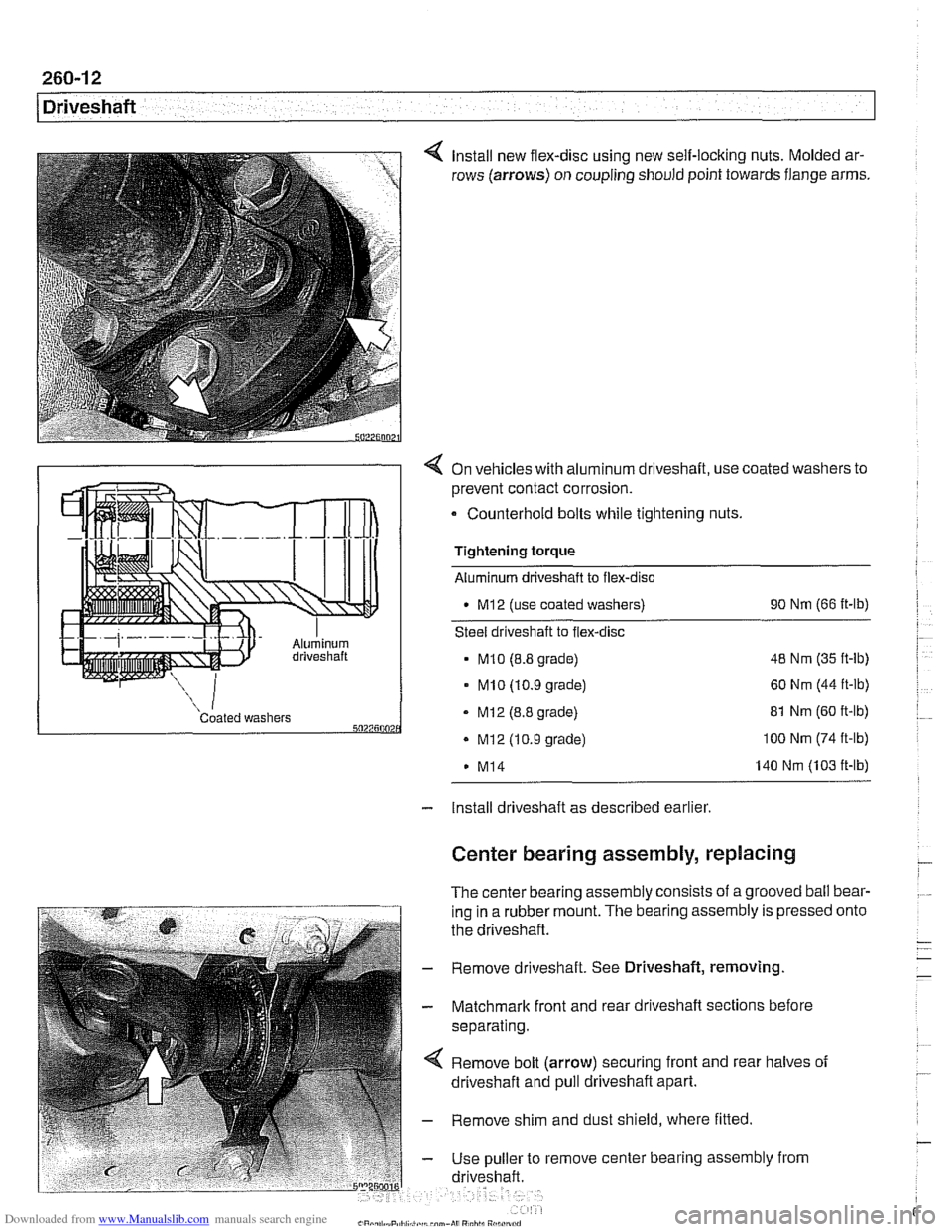
Install new flex-disc using new self-locking nuts. Molded ar-
rows (arrows) on coupling should point towards flange arms.
4 On vehicles with aluminum driveshaft, use coated washers to
prevent contact corrosion.
- Counterhold bolts while tightening nuts.
Tightening torque
Aluminum driveshaft to flex-disc
M12 (use coated washers) 90
Nm (66 ft-lb)
Steel driveshaft to flex-disc
MI0 (8.8 grade) 48
Nm (35 ft-lb)
- MI0 (10.9 grade) 60 Nm (44 ft-lb)
Coated washers - MI2 (8.8 grade) 5027500 . Mi2 (10.9 grade)
M14 81
Nm (60 ft-lb) 100 Nm (74 ft-lb)
140 Nm (103 ft-lb)
- Install driveshaft as described earlier
Center bearing assembly, replacing
The center bearing assembly consists of a grooved ball bear-
ing in a rubber mount. The bearing assembly is pressed
the driveshaft.
- Remove driveshaft. See Driveshaft, removing
- Matchmark front and rear driveshaft sections before
separating.
Remove bolt (arrow) securing front and rear halves of
driveshaft and pull driveshaft apart.
- Remove shim and dust shield, where fitted
- Use puller to remove center bearing assembly from
driveshaft. onto
Page 643 of 1002
Downloaded from www.Manualslib.com manuals search engine
Front ~us~ensionl
Spread steering knuckle slot in
tool
31 2 200.
pinch collarwith BMW special
4 Worlting in engine compartment at strut tower:
- If applicable, disconnect plug connector at top of strut for
Electronic Damper Control and remove cap from cable.
Remove upper strut bearing mounting fasteners
(arrows).
WARNING-
Do not remove centerstrut retaining nut.
4 Use lever to push down on wheel hub. Tilt strut outward
NOTE-
Use masking tape to protect fender arch from possible dam-
age.