Page 3 of 62
15-3
Cylinder head without oil lines to camshaft
bearings
1 -
Double bearing cap
Lightly coat with sealant 454 300 02 A2
before installing page 15
-36
2 -
Bolt
10 Nm (7ft lb)
3 -
Exhaust camshaft bearing cap Watch guide sleeveNote installation position and numbering
page 15
-36
Lightly coat last bearing cap (after chain)
with D454 300 A2 sealant before installing
4 -
Exhaust camshaft Checking axial clearance page 15
-42
Removing and installing page 15
-31
Check radial clearance using Plastigage
(hydraulic valve lifters removed):
Wear limit: 0.1 mm (0.004 in.)Max. run-out: 0.01 mm (0.0004 in.)
Pa
ge 3 of 62 Valve
gear, servicin
g
11/21/2002 htt
p://127.0.0.1:8080/audi/servlet/Dis
play?action=Goto&t
yp
e=re
pair&id=AUDI.B5.GE03.15.1
Page 8 of 62
15-7
Cylinder head with oil lines to camshaft
bearings
1 -
Double bearing cap
Lightly coat with 454 300 02 A2 sealant
before installing page 15
-17
2 -
Exhaust camshaft bearing cap
With oil line connectorWatch guide sleeveNote installation position and numbering
page15
-31
Lightly coat last bearing cap (after chain)
with D454 300 A2 sealant before installing
3 -
Bolt 10 Nm (7 ft lb)
4 -
Oil line Exhaust sideFrom VIN 8D-W-005 001For bearing cap lubricationNote installed position Fig. 4
Pa
ge 8 of 62 Valve
gear, servicin
g
11/21/2002 htt
p://127.0.0.1:8080/audi/servlet/Dis
play?action=Goto&t
yp
e=re
pair&id=AUDI.B5.GE03.15.1
Page 41 of 62
15-35
The distance between the two arrows/paint marks is equivalent to 16 drive
chain rollers.
The notch on the exhaust camshaft is slightly offset inward toward chain
roller -1-.
Note:
Do not mark chain using punch, filing a notch or similar.
- Remove camshaft adjuster retaining bolts.
- Remove bearing caps -1-,-3-,-5- and -7- and lay on a clean surface in
correct order.
- Alternating in diagonal sequence, loosen bearing caps -2- and -4- of
intake and exhaust camshafts and remove.
- Remove both camshafts together with camshaft adjuster.
Pa
ge 41 of 62 Valve
gear, servicin
g
11/21/2002 htt
p://127.0.0.1:8080/audi/servlet/Dis
play?action=Goto&t
yp
e=re
pair&id=AUDI.B5.GE03.15.1
Page 43 of 62

15-37
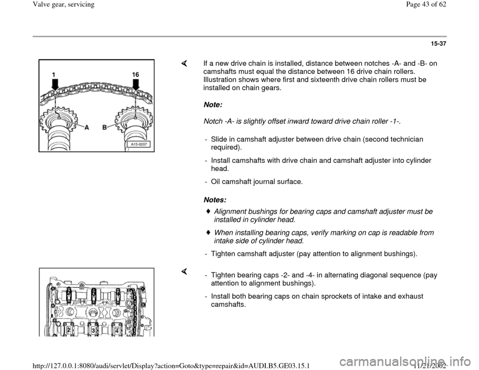
If a new drive chain is installed, distance between notches -A- and -B- on
camshafts must equal the distance between 16 drive chain rollers.
Illustration shows where first and sixteenth drive chain rollers must be
installed on chain gears.
Note:
Notch -A- is slightly offset inward toward drive chain roller -1-.
Notes: - Slide in camshaft adjuster between drive chain (second technician
required).
- Install camshafts with drive chain and camshaft adjuster into cylinder
head.
- Oil camshaft journal surface.
Alignment bushings for bearing caps and camshaft adjuster must be
installed in cylinder head. When installing bearing caps, verify marking on cap is readable from
intake side of cylinder head.
- Tighten camshaft adjuster (pay attention to alignment bushings).
- Tighten bearing caps -2- and -4- in alternating diagonal sequence (pay
attention to alignment bushings).
- Install both bearing caps on chain sprockets of intake and exhaust
camshafts.
Pa
ge 43 of 62 Valve
gear, servicin
g
11/21/2002 htt
p://127.0.0.1:8080/audi/servlet/Dis
play?action=Goto&t
yp
e=re
pair&id=AUDI.B5.GE03.15.1
Page 44 of 62
15-38
- Verify correct position of both camshafts.
Both camshaft markings must align with arrows on bearing caps
(arrows).
The distance between the two arrows/paint markings is equivalent to 16
drive chain rollers.
Note:
The notch on exhaust camshaft is slightly offset inward toward drive chain
roller -1-.
Pa
ge 44 of 62 Valve
gear, servicin
g
11/21/2002 htt
p://127.0.0.1:8080/audi/servlet/Dis
play?action=Goto&t
yp
e=re
pair&id=AUDI.B5.GE03.15.1
Page 45 of 62
15-39
- Lightly coat hatched surface of double bearing cap -1- and bearing cap
-7-...
- ...with sealant D 454 300 A2 and install bearing cap (pay attention to
alignment bushings).
- Install the other bearing caps (pay attention to alignment bushings).
- Replace oil lines for camshaft bearing lubrication and install.
- Replace oil seal for intake and exhaust camshafts page 15
-14
.
- Remove 3366 bracket tensioner.
Pa
ge 45 of 62 Valve
gear, servicin
g
11/21/2002 htt
p://127.0.0.1:8080/audi/servlet/Dis
play?action=Goto&t
yp
e=re
pair&id=AUDI.B5.GE03.15.1
Page 54 of 62
15-47
Valve stem oil seals, replacing
Cylinder head installed
Lock carrier in service position page 13
-1
- Remove ribbed belt page 13
-8 .
- Remove toothed belt page 13
-12
.
- Remove camshafts page 15
-31
.
- Remove valve lifters (do not interchange) and
lay aside with contact surface facing down.
- Remove spark plugs.
- Move piston for individual cylinder to Bottom
Dead Center (BDC) position.
Note:
Lightly tap valve lever to loosen stuck valve
keepers.
Exhaust side
Note:
Pa
ge 54 of 62 Valve
gear, servicin
g
11/21/2002 htt
p://127.0.0.1:8080/audi/servlet/Dis
play?action=Goto&t
yp
e=re
pair&id=AUDI.B5.GE03.15.1
Page 56 of 62
15-48
- Attach 2036 adjustable rod (as shown in figure) using M6 x 40 bolts
with large washers.
- Remove valve spring using VW541/1 lever and VW541/5 valve spring
tensioner.
- Remove valve spring and valve spring plate.
- Remove valve stem oil seal using 3047A slide hammer.
- Place plastic sleeve -A- on valve stem to prevent damage to new valve
stem oil seals.
- Lightly lubricate sealing lip with oil.
- Insert valve stem oil seal -B- (without oiling outside of seal) into 3129
seal driver and carefully slide onto valve guide.
- When installing new valve, lightly oil valve stem before installing.
Pa
ge 56 of 62 Valve
gear, servicin
g
11/21/2002 htt
p://127.0.0.1:8080/audi/servlet/Dis
play?action=Goto&t
yp
e=re
pair&id=AUDI.B5.GE03.15.1