Page 270 of 339

Downloaded from www.Manualslib.com manuals search engine 01-262
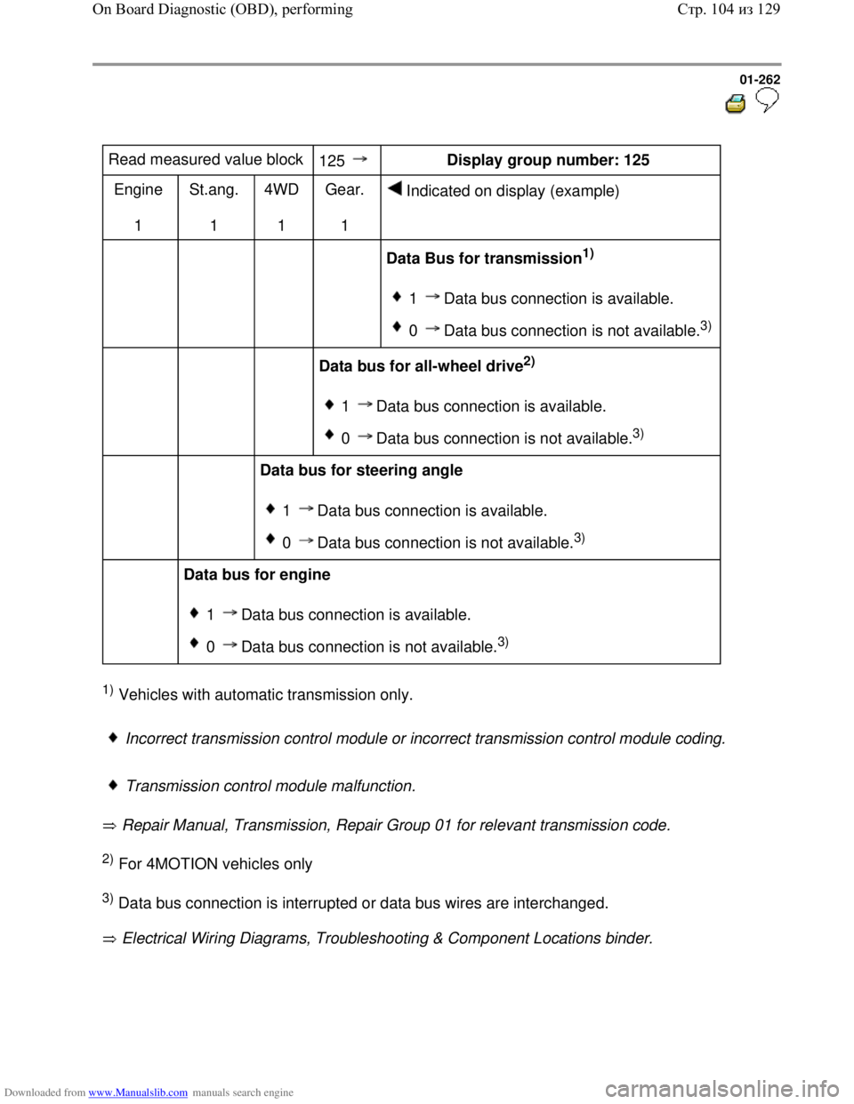
Read measured value block
125 Display group number: 125
Engine
1 St.ang.
1 4WD
1 Gear.
1 Indicated on display (example)
Data Bus for transmission1)
1 Data bus connection is available.
0 Data bus connection is not available.3)
Data bus for all-wheel drive2)
1 Data bus connection is available.
0 Data bus connection is not available.3)
Data bus for steering angle
1 Data bus connection is available.
0 Data bus connection is not available.3)
Data bus for engine
1 Data bus connection is available.
0 Data bus connection is not available.3)
1) Vehicles with automatic transmission only.
Incorrect transmission control module or incorrect transmission control module coding.
Transmission control module malfunction.
Repair Manual, Transmission, Repair Group 01 for relevant transmission code.
2) For 4MOTION vehicles only
3) Data bus connection is interrupted or data bus wires are interchanged.
Electrical Wiring Diagrams, Troubleshooting & Component Locations binder.
Стр. 104из 129 On Board Diagnostic (OBD), performing
Page 272 of 339

Downloaded from www.Manualslib.com manuals search engine 01-264
Basic setting, initiating
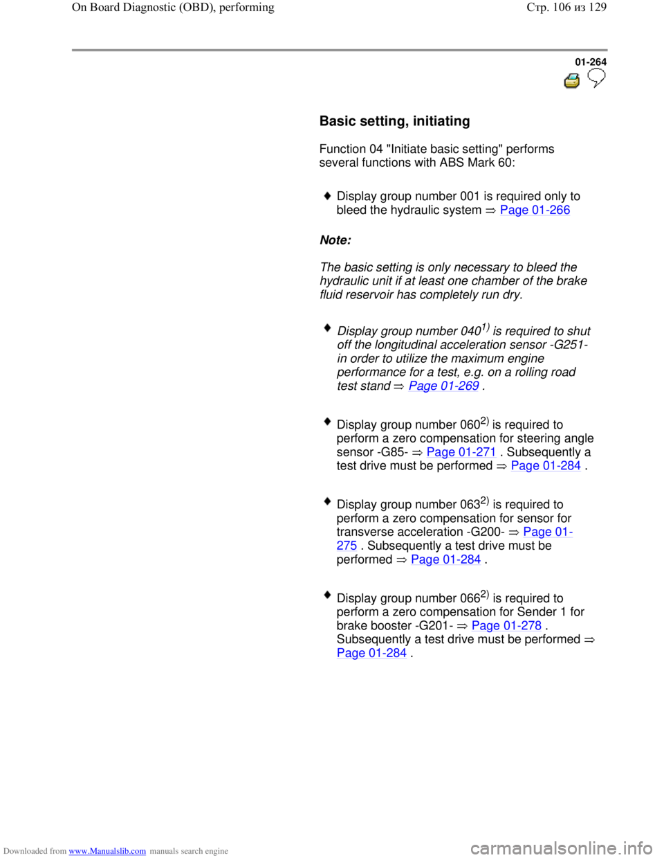
Function 04 "Initiate basic setting" performs
several functions with ABS Mark 60:
Display group number 001 is required only to
bleed the hydraulic system Page 01
-266
Note:
The basic setting is only necessary to bleed the
hydraulic unit if at least one chamber of the brake
fluid reservoir has completely run dry.
Display group number 0401) is required to shut
off the longitudinal acceleration sensor -G251-
in order to utilize the maximum engine
performance for a test, e.g. on a rolling road
test stand Page 01
-269 .
Display group number 0602) is required to
perform a zero compensation for steering angle
sensor -G85- Page 01
-271 . Subsequently a
test drive must be performed Page 01
-284 .
Display group number 0632) is required to
perform a zero compensation for sensor for
transverse acceleration -G200- Page 01
-
275 . Subsequently a test drive must be
performed Page 01
-284 .
Display group number 0662) is required to
perform a zero compensation for Sender 1 for
brake booster -G201- Page 01
-278 .
Subsequently a test drive must be performed
Page 01
-284 .
Стр. 106из 129 On Board Diagnostic (OBD), performing
Page 273 of 339

Downloaded from www.Manualslib.com manuals search engine 01-265
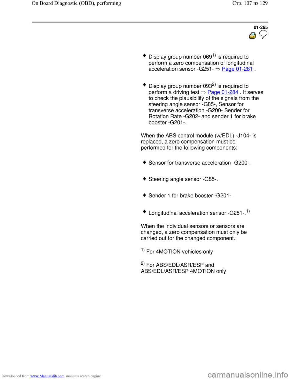
Display group number 0691) is required to
perform a zero compensation of longitudinal
acceleration sensor -G251- Page 01
-281 .
Display group number 0932) is required to
perform a driving test Page 01
-284. It serves
to check the plausibility of the signals from the
steering angle sensor -G85-, Sensor for
transverse acceleration -G200- Sender for
Rotation Rate -G202- and sender 1 for brake
booster -G201-.
When the ABS control module (w/EDL) -J104- is
replaced, a zero compensation must be
performed for the following components:
Sensor for transverse acceleration -G200-.
Steering angle sensor -G85-.
Sender 1 for brake booster -G201-.
Longitudinal acceleration sensor -G251-.1)
When the individual sensors or sensors are
changed, a zero compensation must only be
carried out for the changed component.
1) For 4MOTION vehicles only
2) For ABS/EDL/ASR/ESP and
ABS/EDL/ASR/ESP 4MOTION only
Стр. 107из 129 On Board Diagnostic (OBD), performing
Page 274 of 339
Downloaded from www.Manualslib.com manuals search engine 01-266
Display group number 01: Bleeding
hydraulic unit
Special tools and equipment
Note:
All functions which could previously be
performed with V.A.G 1551 can now also
be carried out with the tester VAS 5051.
Repair Manual, Brake System, Repair
Group 47; Bleeding brake system, vehicles
with and without ABS
VAS 5234 Brake filler and bleeder unit
- Connect brake filling and bleeder unit
VAS 5234.
- Pre-bleed brake system
- Connect V.A.G 1551 scan tool and select
(address word 03) brake electronics
control module with ignition switched on;
Page 01
-163 .
Rapid data transfer HELP
Select function XX Indicated on display
- Press keys 0 and 4. (The function
"Initiating basic setting" is selected with
04).
Стр. 108из 129 On Board Diagnostic (OBD), performing
Page 275 of 339
Downloaded from www.Manualslib.com manuals search engine 01-267
Rapid data transfer Q
04 - Basic settin
g
Indicated on display:
- Confirm entry with key Q.
Basic setting HELP
Enter dis
play group number XXX
Indicated on display:
The following cycle of steps must be
repeated 8 times according to the basic
setting prescribed by V.A.G 1551 or
tester VAS 5051. - Press keys 0, 0 and 1
- Confirm entry with key Q.
Basic setting 1 ON
De
press pedal and hold...
Indicated on display:
- Operate pedal with substantial foot
pressure and hold.
Pedal moves down
Hydraulic pump runs
Pedal comes back
Basic setting 1
Rel. pedal; FR/FL bleed screw OPEN Indicated on display:
- Press key 3 on V.A.G 1551 or arrow up
key on VAS 5051
Basic setting 1 ON
Please wait...
(10 secs.)
Indicated on display:
Hydraulic pump runs
Стр. 109из 129 On Board Diagnostic (OBD), performing
Page 276 of 339
Downloaded from www.Manualslib.com manuals search engine 01-268
Basic setting 2
De
pr. pedal 10X; bleed screw CLOSED
Indicated on display:
- Press key 3 on V.A.G 1551 or arrow up
key on VAS 5051
System in basic setting 17
Part. bleedin
g ended...
When all 8 cycles have been performed,
this message appears on the display:
-
Press key.
Rapid data transfer HELP
Select function XX Indicated on display:
- Press keys -0- and -6-, this ends the
output.
Rapid data transfer Q
06 - End output Indicated on display
- Confirm entry with Q key
Rapid data transfer Help
Enter address word XX
Indicated on display
Repair Manual, Brake System, Repair
Group 47; Bleeding brake system, vehicles
with and without ABS - Press C key
- Switch off ignition.
- Disconnect connection to V.A.G 1551
scan tool.
- Bleed brake system again
For vehicles with ABS/EDL/ASR/ESP:
perform zero compensation for Sender
1 for brake booster -G201- Page 01
-
278 .
Стр. 110из 129 On Board Diagnostic (OBD), performing
Page 277 of 339
Downloaded from www.Manualslib.com manuals search engine 01-269
Display group number 40: switching off
longitudinal acceleration sensor -G251-
All functions which could previously be
performed with V.A.G 1551 can now also be
carried out with the tester VAS 5051.
Display group 040 is necessary for shutting off
longitudinal acceleration sensor -G251- in order
to utilize the maximum engine performance for
a test, e.g. on a rolling road test bed. In
addition, the all wheel drive is shut off and the
vehicle behaves like a front wheel drive vehicle.
Switch ignition off and on again to reactivate the
longitudinal acceleration sensor -G251-.
- Connect V.A.G 1551 scan tool and select
(address word 03) brake electronics control
module with ignition switched on; Page 01
-
163 .
Стр. 111из 129 On Board Diagnostic (OBD), performing
Page 278 of 339
Downloaded from www.Manualslib.com manuals search engine 01-270
Rapid data transfer HELP
Enter address word XX Indicated on display:
- Press keys 0 and 4. (The function
"Initiating basic setting" is selected with
04).
Rapid data transfer Q
04 - Basic settin
g
Indicated on display:
- Confirm entry with key Q.
Basic setting HELP
Enter displa
y group number XXX
Indicated on display:
- Press keys 0, 4 and 0
- Confirm entry with key Q.
ABS warning light flashes.
Basic setting 40 Indicated on display:
- The longitudinal acceleration sensor -
G251- is now switched off.
- After completing the checks, reactivate
the longitudinal acceleration sensor -
G251- by switching the ignition off and
on again, once.
Стр. 112из 129 On Board Diagnostic (OBD), performing