Page 295 of 339

Downloaded from www.Manualslib.com manuals search engine 01-287
Login procedure
All functions that have so far been carried out
with V.A.G 1551 can now also be carried out
with the tester VAS 5051.
The login procedure can only be performed
once per calibration.
Coding is only possible after the workshop code
(WSC) has been introduced into V.A.G 1551 or
the new tester VAS 5051.
Test sequence
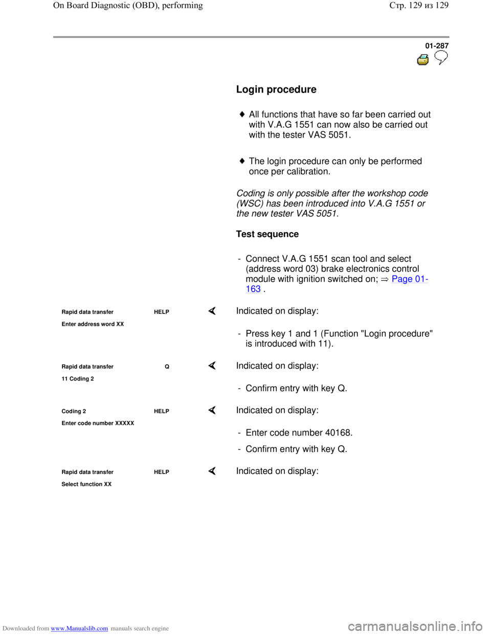
- Connect V.A.G 1551 scan tool and select
(address word 03) brake electronics control
module with ignition switched on; Page 01
-
163 .
Rapid data transfer HELP
Enter address word XX Indicated on display:
- Press key 1 and 1 (Function "Login procedure"
is introduced with 11).
Rapid data transfer Q
11 Codin
g 2
Indicated on display:
- Confirm entry with key Q.
Coding 2 HELP
Enter code number XXXXX Indicated on display:
- Enter code number 40168.
- Confirm entry with key Q.
Rapid data transfer HELP
Select function XX Indicated on display:
Стр. 129из 129 On Board Diagnostic (OBD), performing
Page 302 of 339
Downloaded from www.Manualslib.com manuals search engine 01-294
Contact
Wiring connection to component ...
13
ASR/ESP button -E256-
14
Coding bridge to contact 38 (vehicles with ABS and ABS/EDL/ASR front wheel
drive only)
15
Data bus wire Wiring diagrams
16 Ground point on left-hand longitudinal member
17
Vacant
18
Sender 1 for brake booster -G201- voltage supply
19
Sender 1 for brake booster -G201- signal wire
20
Sender 1 for brake booster -G201- ground wire
21
Vacant
22
Vacant
23
Vacant
24
Ground wire for sensor for transverse acceleration -G200- and sender for
rotation rate -G202-
Ground wire for ESP-sensor unit -G419-, vehicles from 02.02
25
Vacant
Data bus wire for ESP-sensor unit -G419-, vehicles from 02.02
26
Voltage supply for sensor for transverse acceleration -G200- and sender for
rotation rate -G202-
Стр. 7из 38 Electrical check of Mark 60
Page 304 of 339
Downloaded from www.Manualslib.com manuals search engine 01-296
Contact
Wiring connection to component ...
39
Vacant
40
Sender for rotation rate -G202- signal wire
41
Brake light switch -F-
42
Right rear ABS wheel speed sensor -G44-
43
Right rear ABS wheel speed sensor -G44-
44
Vacant
45
Left front ABS wheel speed sensor -G47-
46
Left front ABS wheel speed sensor -G47-
47
Ground point on left-hand longitudinal member
Стр. 9из 38 Electrical check of Mark 60
Page 305 of 339

Downloaded from www.Manualslib.com manuals search engine 01-297
Test step overview
Component to be tested
Voltage supply for ABS hydraulic pump -V64- to ABS control module
(w/EDL) -J104- - Perform test
step 1
Voltage supply for valves in ABS hydraulic unit -N55- to ABS control
module (w/EDL) -J104- - Perform test
step 2
Voltage supply (ignition/starter switch) to ABS control module (w/EDL) -
J104- - Perform test
step 3
Function of brake light switch -F-
- Perform test
step 4
Resistance of right front ABS wheel speed sensor -G45-
- Perform test
step 5
Resistance of left front ABS wheel speed sensor -G47-
- Perform test
step 6
Resistance of right rear ABS wheel speed sensor -G44-
- Perform test
step 7
Resistance of left rear ABS wheel speed sensor -G46-
- Perform test
step 8
Voltage signal of right front ABS wheel speed sensor -G45-
- Perform test
step 9
Voltage signal of left front ABS wheel speed sensor -G47-
- Perform test
step 10
Voltage signal of right rear ABS wheel speed sensor -G44-
- Perform test
step 11
Стр. 10из 38 Electrical check of Mark 60
Page 306 of 339

Downloaded from www.Manualslib.com manuals search engine 01-298
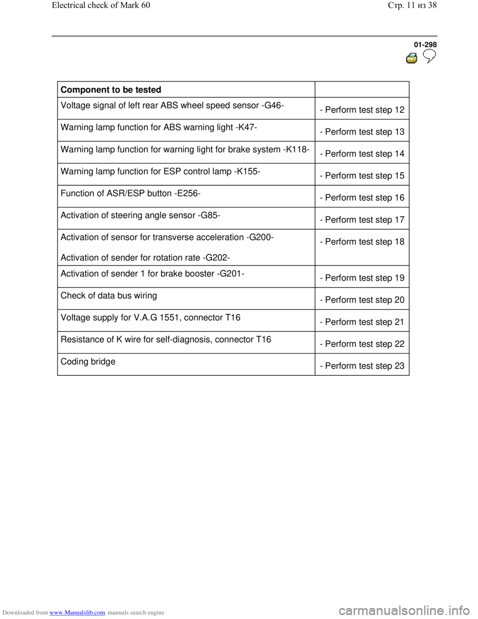
Component to be tested
Voltage signal of left rear ABS wheel speed sensor -G46-
- Perform test step 12
Warning lamp function for ABS warning light -K47-
- Perform test step 13
Warning lamp function for warning light for brake system -K118-
- Perform test step 14
Warning lamp function for ESP control lamp -K155-
- Perform test step 15
Function of ASR/ESP button -E256-
- Perform test step 16
Activation of steering angle sensor -G85-
- Perform test step 17
Activation of sensor for transverse acceleration -G200-
Activation of sender for rotation rate -G202- - Perform test step 18
Activation of sender 1 for brake booster -G201-
- Perform test step 19
Check of data bus wiring
- Perform test step 20
Voltage supply for V.A.G 1551, connector T16
- Perform test step 21
Resistance of K wire for self-diagnosis, connector T16
- Perform test step 22
Coding bridge
- Perform test step 23
Стр. 11из 38 Electrical check of Mark 60
Page 309 of 339

Downloaded from www.Manualslib.com manuals search engine 01-301
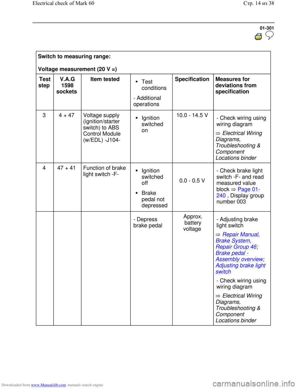
Switch to measuring range:
Voltage measurement (20 V =)
Test
step V.A.G
1598
sockets Item tested
Test
conditions
- Additional
operations Specification
Measures for
deviations from
specification
3 4 + 47 Voltage supply
(ignition/starter
switch) to ABS
Control Module
(w/EDL) -J104-
Ignition
switched
on 10.0 - 14.5 V
Electrical Wiring
Diagrams,
Troubleshooting &
Component
Locations binder - Check wiring using
wiring diagram
4 47 + 41 Function of brake
light switch -F- Ignition
switched
off
Brake
pedal not
depressed
0.0 - 0.5 V - Check brake light
switch -F- and read
measured value
block Page 01-
240 , Display group
number 003
- Depress
brake pedal Approx.
battery
voltage
Repair Manual,
Brake System,
Repair Group 46;
Brake pedal -
Assembly overview;
Adjusting brake light
switch
Electrical Wiring
Diagrams,
Troubleshooting &
Component
Locations binder - Adjusting brake
light switch
- Check wiring using
wiring diagram
Стр. 14из 38 Electrical check of Mark 60
Page 310 of 339
Downloaded from www.Manualslib.com manuals search engine 01-302
Switch to measuring range:
Resistance measurement (2 k )
Test
step V.A.G
1598
sockets Item tested Test
conditions
- Additional
operations Specification
Measures for
deviations from
specification
5 33 + 34 Resistance of
right front ABS
wheel speed
sensor -G45-
Ignition
switched
off 1.0 - 1.3 k
Electrical Wiring
Diagrams,
Troubleshooting &
Component Locations
binder
If no malfunction can be
located in the wiring:
Repair Manual, Brake
System, Repair Group
45; Removing and
installing parts of ABS
system on front and rear
axles - Check wiring using
wiring diagram
- Wiggle wiring during
test
- Replace right front
ABS wheel speed
sensor -G45-
Стр. 15из 38 Electrical check of Mark 60
Page 311 of 339
Downloaded from www.Manualslib.com manuals search engine 01-303
Switch to measuring range:
Resistance measurement (2 k )
Test
step V.A.G
1598
sockets Item tested Test
conditions
- Additional
operations Specification
Measures for
deviations from
specification
6 45 + 46 Resistance of
left front ABS
wheel speed
sensor -G47-
Ignition
switched
off 1.0 - 1.3 k
Electrical Wiring
Diagrams,
Troubleshooting &
Component Locations
binder
If no malfunction can be
located in the wiring:
Repair Manual, Brake
System, Repair Group
45; Removing and
installing parts of ABS
system on front and rear
axles - Check wiring using
wiring diagram
- Wiggle wiring during
test
- Replace left front ABS
wheel speed sensor -
G47-
Стр. 16из 38 Electrical check of Mark 60