Page 2 of 339

Downloaded from www.Manualslib.com manuals search engine 01-1
ABS ITT Mark 20 IE On Board
Diagnostic (OBD)
Function
Since the control modules are interconnected
with CAN-bus, always begin OBD by checking
the Diagnostic Trouble Code (DTC) memories
of all the control modules in the vehicle.
This occurs in the Automatic test sequence and
is activated with key function 00.
When doing this, check to see if there are
DTCs stored which may influence the ABS.
On Board Diagnostic (OBD) relates to the
electrical/electronic part of the ABS, i.e. only
malfunctions via the electrical connection to the
control module are recognized (e.g. speed
sensor open circuit).
The 25-pin ABS Control Module (w/EDL) -J104-
forms with the hydraulic unit a compact unit.
The unit is located on the left in the engine
compartment. The control module is equipped
with a DTC memory. The diagnostic connection
is located in the center console below the
heating/air conditioning controls.
The control module recognizes malfunctions
during vehicle operation and stores them in a
permanent memory, the contents of which
remain even during periods of no battery
voltage.
Стр. 1из 8 ABS ITT Mark 20 IE On Board Diagnostic (OBD)
Page 26 of 339

Downloaded from www.Manualslib.com manuals search engine 01-23
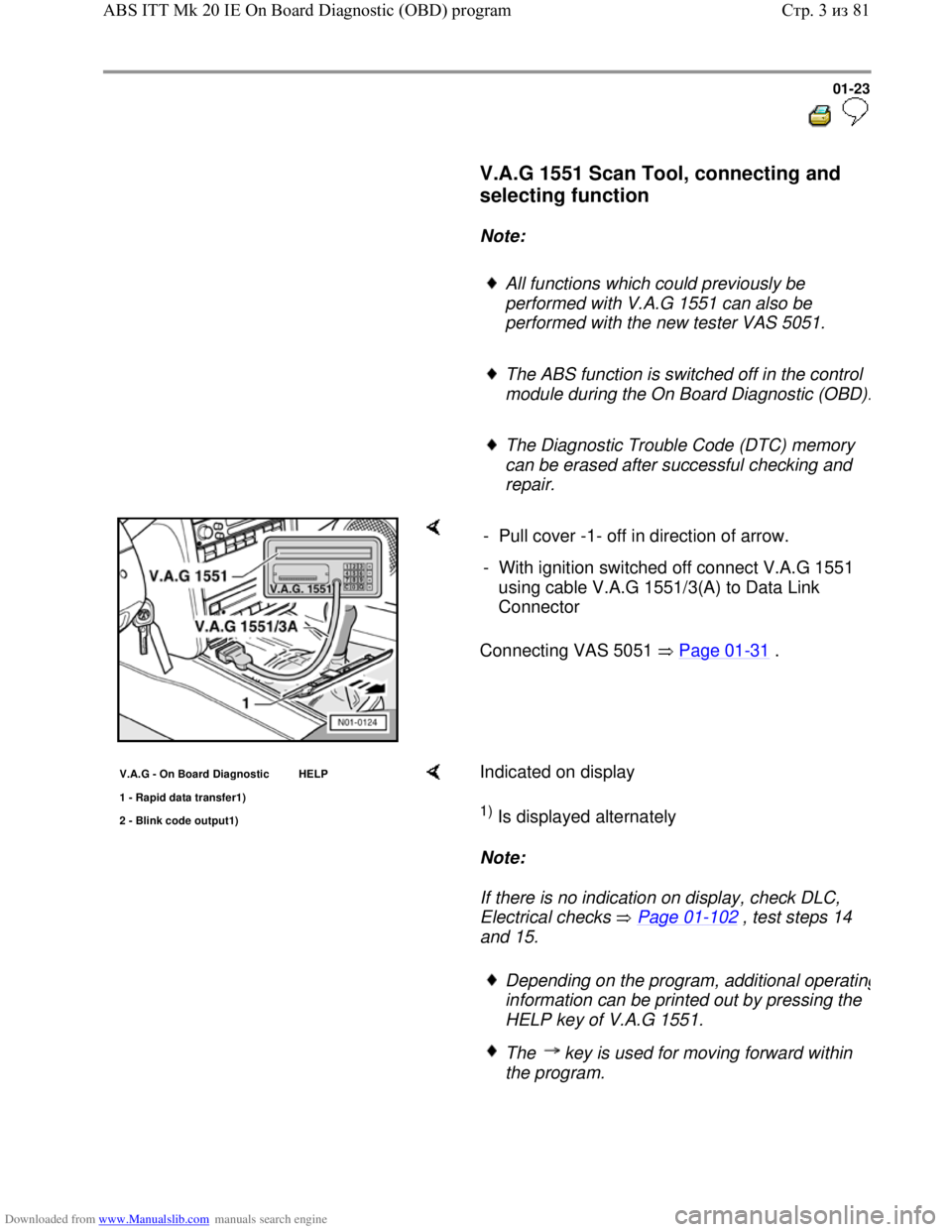
V.A.G 1551 Scan Tool, connecting and
selecting function
Note:
All functions which could previously be
performed with V.A.G 1551 can also be
performed with the new tester VAS 5051.
The ABS function is switched off in the control
module during the On Board Diagnostic (OBD)
.
The Diagnostic Trouble Code (DTC) memory
can be erased after successful checking and
repair.
Connecting VAS 5051 Page 01-31 . - Pull cover -1- off in direction of arrow.
- With ignition switched off connect V.A.G 1551
using cable V.A.G 1551/3(A) to Data Link
Connector
V.A.G - On Board Diagnostic HELP
1 - Ra
pid data transfer1)
2 - Blink code output1)
Indicated on display
1) Is displayed alternately
Note:
If there is no indication on display, check DLC,
Electrical checks Page 01
-102 , test steps 14
and 15.
Depending on the program, additional operating
information can be printed out by pressing the
HELP key of V.A.G 1551.
The key is used for moving forward within
the program.
Стр. 3из 81 ABS ITT Mk 20 IE On Board Diagnostic (OBD) program
Page 27 of 339
Downloaded from www.Manualslib.com manuals search engine 01-24
The PRINT key is used for switching on the
printer (warning lamp in key comes on).
- Switch ignition on.
- Switch on printer with Print key (indicator lamp in
key lights up).
- Press key -1- for "Rapid data transfer" operating
mode.
Rapid data transfer HELP
Enter address word XX Indicated on display
- Press keys -0- and -3-; 03 inputs the address
word of the vehicle system to be tested "Brake
electronics".
Rapid data transfer Q
03 - Brake electronics Indicated on display
- Confirm input with Q key.
1J0 907 379 D ABS 20 IE CAN 0001
Coding 03604 WSC XXXXX
Display shows e.g.
Displayed is:
e.g. (1J0 907 379 D)
Allocation of control module see Parts catalog
Electrical Wiring Diagrams, Troubleshooting &
Component Locations binder
The control module identification number.
System designation (ABS 20 IE)
Data BUS present. (CAN)
Стр. 4из 81 ABS ITT Mk 20 IE On Board Diagnostic (OBD) program
Page 28 of 339

Downloaded from www.Manualslib.com manuals search engine 01-25
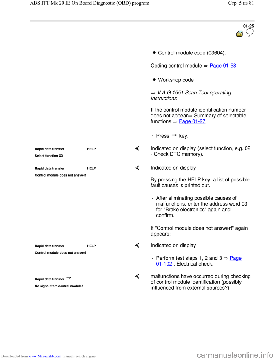
Control module code (03604).
Coding control module Page 01
-58
Workshop code
V.A.G 1551 Scan Tool operating
instructions
If the control module identification number
does not appear Summary of selectable
functions Page 01
-27
-
Press key.
Rapid data transfer HELP
Select function XX Indicated on display (select function, e.g. 02
- Check DTC memory).
Rapid data transfer HELP
Control module does not answer! Indicated on display
By pressing the HELP key, a list of possible
fault causes is printed out.
If "Control module does not answer!" again
appears: - After eliminating possible causes of
malfunctions, enter the address word 03
for "Brake electronics" again and
confirm.
Rapid data transfer HELP
Control module does not answer! Indicated on display
- Perform test steps 1, 2 and 3 Page
01-102 , Electrical check.
Rapid data transfer
No signal from control module!
malfunctions have occurred during checking
of control module identification (possibly
influenced from external sources?)
Стр. 5из 81 ABS ITT Mk 20 IE On Board Diagnostic (OBD) program
Page 29 of 339
Downloaded from www.Manualslib.com manuals search engine 01-26
- Check DLC as well as voltage supply and
Ground connection for ABS Control Module
(w/EDL) -J104-, Electrical check, Page 01
-
102 .
- After repairing possible causes of malfunction,
again enter address word 03 for "Brake
electronics" and confirm with Q key.
Стр. 6из 81 ABS ITT Mk 20 IE On Board Diagnostic (OBD) program
Page 31 of 339
Downloaded from www.Manualslib.com manuals search engine 01-28
Diagnostic Trouble Code (DTC),
memory
All functions which could previously be
performed with V.A.G 1551 can also be
performed with the new tester VAS 5051.
Rapid data transfer HELP
Select function XX Indicated on display:
- Press keys -0- and -2-; 02 enters the
"Check DTC memory" function.
Rapid data transfer Q
02 - Check DTC memor
y
Indicated on display
- Confirm entry with Q key.
X DTCs recognised! The number of stored DTCs or "No DTCs
recognized" appears in the display.
-
Press key.
The stored DTCs are displayed and
printed out one after the other.
- With DTC information print-out eliminate
malfunctions according to DTC table,
Page 01
-35 .
As with "No DTC recognized", the
program returns to the start position after
pressing the key:
Rapid data transfer HELP
Select function XX Indicated on display
- End output (Function 06) Page 01
-56 .
Стр. 8из 81 ABS ITT Mk 20 IE On Board Diagnostic (OBD) program
Page 33 of 339
Downloaded from www.Manualslib.com manuals search engine 01-30
Automatic test sequence
The automatic test sequence checks all the
Diagnostic Trouble Code (DTC) memories
of the control modules.
- Switch ignition on.
V.A.G - On Board Diagnostic HELP
1 - Ra
pid data transfer1)
2 - Blink code output1)
Indicated on display
1) Is displayed alternately
- Press key -1- for "Rapid data transfer"
operating mode.
- Switch on printer with the Print key
(indicator lamp in key lights up).
Rapid data transfer HELP
Select function XX Indicated on display
- Press key -0- twice; 00 enters "Automatic
test sequence" function.
- Confirm entry with Q key.
1J0 907 379 D ABS 20 IE CAN0001
Coding 03604 WSC XXXXX
The V.A.G 1551 Scan Tool display will
show the control module identification, e.g.:
Thereafter all control module
identifications with eventual DTC
memory entries are displayed
Стр. 10из 81 ABS ITT Mk 20 IE On Board Diagnostic (OBD) program
Page 38 of 339

Downloaded from www.Manualslib.com manuals search engine 01-35
Diagnostic Trouble Code (DTC) table
Note on DTC table:
When beginning OBD of the vehicle control modules, always start with function "Automatic
test sequence" by pressing keys 0 and 0 because the control modules are interconnected
with a data bus wire. This checks the DTC memories of the control modules in the vehicle.
All the possible DTCs which can be recognized by the ABS control module -J104- and
printed-out on V.A.G 1551 or VAS 5051, are listed on the following pages according to the
5-digit DTC.
DTC appears (in the "Rapid data transfer" mode) only on the print-out.
Example:
DTC P code DTC type code
5-digit 5-digit 3-digit
18256 P1848 035
The 5-digit P code which may appear next to the DTC, is for use with the On Board
Diagnostic (OBD) II and may be disregarded.
The 3-digit DTC type code is a data code and may be disregarded, but the DTC type text is
of use.
Before replacing components indicated as being faulty, check all the appropriate
connectors, wiring and Ground connections using the wiring diagram
Electrical Wiring Diagrams, Troubleshooting & Component Locations binder
On completion of repairs always check the DTC memory with V.A.G 1551 Scan Too. or the
tester VAS 5051 and erase.
Carry out road test exceeding 20 km/h (13 mph).
After the road test check DTC memory again.
Стр. 15из 81 ABS ITT Mk 20 IE On Board Diagnostic (OBD) program