Page 572 of 3115

BR0TD-06
F04984
F05028
F04985
SSTSSTRemoval:
Installation:
F04986
BR-34
- BRAKEPARKING BRAKE
2170 Author�: Date�:
2004 LAND CRUISER (RM1071U)
DISASSEMBLY
1. REMOVE REAR WHEEL
Torque: 103 N´m (1,050 kgf´cm, 76 ft´lbf)
2. REMOVE REAR DISC BRAKE ASSEMBLY
(a) Remove the 2 mounting bolts and remove the disc brake
assembly.
Torque: 103 N´m (1,050 kgf´cm, 76 ft´lbf)
(b) Suspend the disc brake securely. Ensure that the hose is
not stretched.
3. REMOVE DISC
(a) Place matchmarks on the disc and rear hub.
(b) Remove the disc.
HINT:
If the disc cannot be removed easily, turn the shoe adjuster until
the wheel turns freely.
4. REMOVE TENSION SPRING
(a) Using needle-nose pliers, remove the spring from the
rear shoe and backing plate.
(b) Remove the lower side tension spring.
5. REMOVE SHOE RETURN SPRINGS
Using SST, remove the 2 shoe return springs.
SST 09717-20010
HINT:
At the time of installation, using SST, install the rear shoe return
spring and then install the front shoe return spring.
SST 09718-20010
6. REMOVE SHOE STRUT WITH SPRING
7. REMOVE REAR SHOE, ADJUSTER AND TENSION
SPRING
(a) Slide out the rear shoe and remove the adjuster.
(b) Remove the shoe hold-down spring, 2 cups and pin.
Page 2603 of 3115

SS0OJ-10
SS-30
- SERVICE SPECIFICATIONSSUSPENSION AND AXLE
170 Author�: Date�:
2004 LAND CRUISER (RM1071U)
SUSPENSION AND AXLE
SERVICE DATA
Cold tire
inflation
pressure
Tire size
P275/70R16 Front
Rear
200 kPa (2.0 kgf/cm2, 29 psi)*220 kPa (2.2 kgf/cm2, 32 psi)
220 kPa (2.2 kgf/cm2, 32 psi)*240 kPa (2.4 kgf/cm2, 35 psi)
Vehicle height
Front A - B
Rear C - D
71 mm (2.795 in.)
51 mm (2.008 in.)
Camber
Right-left error0°05' ± 45' (0.08° ± 0.75°)
30' (0.5°) or less
Fthl
Caster
Right-left error2°30' ± 45' (2.5° ± 0.75°)
30' (0.5°) or less
Front wheel
alignmentSteering axis inclination
Right-left error12°10' ± 45' (12.17° ± 0.75°)
30' (0.5°) or less
Toe-in (total)
Rack end length difference0°06' ± 12' (0.1° ± 0.2°, 1 ± 2 mm, 0.04 ± 0.08 in.)
3.0 mm (0.118 in.) or less
Wheel angle Inside wheel
Outside wheel: Reference36°42' (33°42' - 36°42')
36.7° (33.7° - 36.7°)
32°36'
32.6°
Front axle hub preload (at starting)42 - 67 N (4.3 - 6.8 kgf, 9.5 - 15.0 lbf)
Front axleSnap ring thickness
1.8 mm (0.0709 in.)
2.0 mm (0.0787 in.)
2.2 mm (0.0866 in.)
2.4 mm (0.0945 in.)
2.6 mm (0.1024 in.)
2.8 mm (0.1102 in.)
Front drive shaftFront drive shaft length573.9 ± 5.0 mm (22.594 ± 0.197 in.)
Ft iUpper suspension arm ball joint turning torque1.0 - 4.4 N´m (10 - 45 kgf´cm, 8.9 - 39 in.´lbf)Front suspensionLower suspension arm ball joint turning torque0.29 - 2.94 N´m (3 - 30 kgf´cm, 2.6 - 26 in.´lbf)
Bearing backlash Max.0.6 mm (0.024 in.)
RlhftAxle shaft deviation Max.0.05 mm (0.0020 in.)Rear axle shaftAxle shaft runout Max.2.0 mm (0.079 in.)
Axle shaft flange runoutMax.0.05 mm (0.0020 in.)
*: Trailer towing
A: Ground clearance of spindle center
B: Ground clearance of lower suspension arm front bolt center
C: Ground clearance of rear axle shaft center
D: Ground clearance of lower control arm front bushing center
Page 2783 of 3115

H20060
2 Times or more
H20058
AB0158
SSTBattery RS-24
- SUPPLEMENTAL RESTRAINT SYSTEMSTEERING WHEEL PAD AND SPIRAL CABLE
2299 Author�: Date�:
2004 LAND CRUISER (RM1071U)
(3) Using 3 wire harness, wind the wire harness at least
2 times each around the bolts installed on the left
and right sides of the steering wheel pad.
CAUTION:
�Tightly wind the wire harness around the bolts so that
there is no slack.
�If there is slackness in the wire harness, the steering
wheel pad may come loose due to the shock when the
airbag is deployed. This is highly dangerous.
(4) Face the upper surface of the steering wheel pad
upward. Separately tie the left and right sides of the
steering wheel pad to the disc wheel through the
hub nut holes. Position the steering wheel pad con-
nector so that it hangs downward through a hub
hole in the disc wheel.
CAUTION:
�Make sure that the wire harness is tight. It is very dan-
gerous when looseness in the wire harness results in
the steering wheel pad coming free through the shock
from the airbag deploying.
�Always tie down the steering wheel pad with the pad
side facing upward. It is very dangerous if the steer-
ing wheel pad is tied down with the metal surface fac-
ing upward as the wire harness will be cut by the
shock caused by the airbag is deployment and the
steering wheel pad will be thrown into the air.
NOTICE:
The disc wheel will be marked by airbag deployment, so
when disposing of the airbag, use a redundant disc wheel.
(c) Check the function of the SST (See step 1-(a)).
SST 09082-00700
Page 2898 of 3115

F04362
90°
F04363
- SUSPENSION AND AXLEFRONT AXLE HUB
SA-17
1967 Author�: Date�:
2004 LAND CRUISER (RM1071U)
(d) Using a spring tension gauge, check the preload.
Preload (at starting):
42 - 67 N (4.3 - 6.8 kgf, 9.5 - 15.0 lbf)
HINT:
Make sure to check preload in the direction of rotation.
If the preload is not within the specified value, adjust it again
with the adjusting nut.
(e) Secure the lock nut by bending one of the lock washer
teeth inward and the other lock washer teeth outward.
4. INSTALL FLANGE
(a) Place a new gasket in position on the axle hub.
(b) Install the flange to the axle hub.
(c) Install the 6 cone washers, washers and new nuts.
Torque: 33 N´m (335 kgf´cm, 24 ft´lbf)
(d) Pull out the drive shaft to the outside of the vehicle and
select the snap ring which ensures the clearance be-
tween the tip of the flange and the snap ring is less than
0.2 mm (0.008 in.).
Snap ring thickness:
1.8 mm (0.0709 in.)2.4 mm (0.0945 in.)
2.0 mm (0.0787 in.)2.6 mm (0.1024 in.)
2.2 mm (0.0866 in.)2.8 mm (0.1102 in.)
(e) Using a snap ring expander, install a new snap ring to the
drive shaft.
(f) Install a new grease cap to the flange.
5. INSTALL BRAKE CALIPER
(a) Install the brake caliper, washers and 2 bolts.
Torque: 123 N´m (1,250 kgf´cm, 91 ft´lbf)
(b) Install the flexible hose and bolt to the steering knuckle.
Torque: 28 N´m (290 kgf´cm, 21 ft´lbf)
6. INSTALL FRONT WHEEL
Torque: 131 N´m (1,340 kgf´cm, 97 ft´lbf)
7. CHECK ABS SPEED SENSOR SIGNAL
(See page DI-505)
Page 2901 of 3115

SA144-04
F04367
F04368
F04369
F04370SST SA-12
- SUSPENSION AND AXLEFRONT AXLE HUB
1962 Author�: Date�:
2004 LAND CRUISER (RM1071U)
REMOVAL
1. REMOVE FRONT WHEEL
2. REMOVE BRAKE CALIPER
(a) Remove the bolt and disconnect the flexible hose from
the steering knuckle.
(b) Remove the 2 bolts, washers and brake caliper.
(c) Support the brake caliper securely.
3. REMOVE FLANGE
(a) Using a screwdriver and hammer, remove the grease cap
from the flange.
(b) Using a snap ring expander, remove the snap ring.
(c) Remove the 6 nuts and washers.
(d) Install the 6 nuts temporarily to protect the threads of the
stud bolts.
(e) Using a brass bar and hammer, tap on the bolt heads and
remove the 6 nuts and cone washers.
(f) Remove the flange and gasket.
4. REMOVE AXLE HUB WITH DISC
(a) Using a screwdriver, release the lock washer.
(b) Using SST, remove the lock nut.
SST 09607-60020
(c) Remove the lock washer.
(d) Using SST, remove the adjusting nut.
SST 09607-60020
(e) Remove the axle hub with disc.
NOTICE:
Be careful not to damage the ABS speed sensor rotor and
oil seal.
(f) Remove the claw washer and bearing from the axle hub.
Page 2965 of 3115
SA148-04
F04340Matchmarks
F04344
F04345
F04340Matchmarks
SA-18
- SUSPENSION AND AXLEFRONT WHEEL HUB BOLT
1968 Author�: Date�:
2004 LAND CRUISER (RM1071U)
FRONT WHEEL HUB BOLT
REPLACEMENT
1. REMOVE FRONT AXLE HUB (See page SA-12)
2. REMOVE HUB BOLT
(a) Mount the axle hub with the disc in a soft jaw vice.
NOTICE:
Close vice until it holds disc, do not tighten further.
(b) Place matchmarks on the axle hub and disc.
(c) Remove the 5 bolts and separate the axle hub from the
disc.
(d) Using a press, remove the hub bolt.
3. INSTALL HUB BOLT
(a) Using an extension bar and press, install a new hub bolt.
(b) Align the matchmarks on the axle hub and disc.
(c) Install the 5 bolts to the axle hub.
Torque: 74 N´m (750 kgf´cm, 55 ft´lbf)
4. INSTALL FRONT AXLE HUB (See page SA-16)
Page 2973 of 3115
SA15D-02
F04386
SST
F04387
F04388
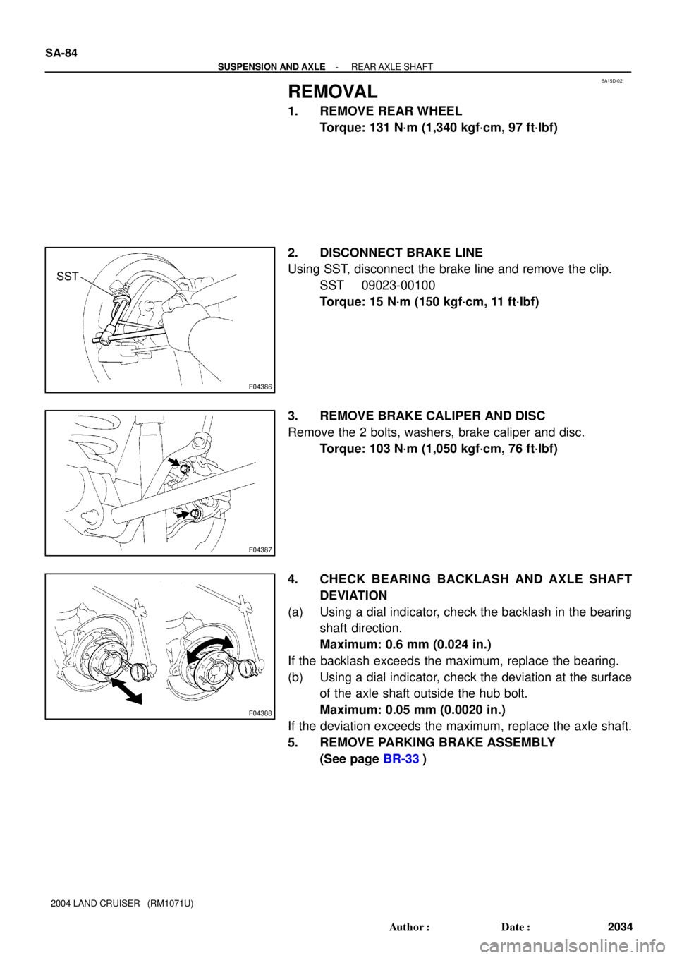
SA-84
- SUSPENSION AND AXLEREAR AXLE SHAFT
2034 Author�: Date�:
2004 LAND CRUISER (RM1071U)
REMOVAL
1. REMOVE REAR WHEEL
Torque: 131 N´m (1,340 kgf´cm, 97 ft´lbf)
2. DISCONNECT BRAKE LINE
Using SST, disconnect the brake line and remove the clip.
SST 09023-00100
Torque: 15 N´m (150 kgf´cm, 11 ft´lbf)
3. REMOVE BRAKE CALIPER AND DISC
Remove the 2 bolts, washers, brake caliper and disc.
Torque: 103 N´m (1,050 kgf´cm, 76 ft´lbf)
4. CHECK BEARING BACKLASH AND AXLE SHAFT
DEVIATION
(a) Using a dial indicator, check the backlash in the bearing
shaft direction.
Maximum: 0.6 mm (0.024 in.)
If the backlash exceeds the maximum, replace the bearing.
(b) Using a dial indicator, check the deviation at the surface
of the axle shaft outside the hub bolt.
Maximum: 0.05 mm (0.0020 in.)
If the deviation exceeds the maximum, replace the axle shaft.
5. REMOVE PARKING BRAKE ASSEMBLY
(See page BR-33)
Page 3053 of 3115
SA15J-02
F04387
F04389
F04390
- SUSPENSION AND AXLEREAR WHEEL HUB BOLT
SA-93
2043 Author�: Date�:
2004 LAND CRUISER (RM1071U)
REAR WHEEL HUB BOLT
REPLACEMENT
1. REMOVE REAR WHEEL
2. REMOVE BRAKE CALIPER AND DISC
(a) Remove the 2 bolts, brake caliper and disc.
(b) Support the brake caliper securely.
3. REMOVE HUB BOLT
Using a brass bar and hammer, remove the hub bolt.
4. INSTALL HUB BOLT
Install a washer and nut to a new hub bolt, as shown in the il-
lustration, and install the hub bolt by torquing the nut.
5. INSTALL DISC AND BRAKE CALIPER
Install the disc and brake caliper with the 2 bolts.
Torque: 103 N´m (1,050 kgf´cm, 76 ft´lbf)
6. INSTALL REAR WHEEL
Torque: 131 N´m (1,340 kgf´cm, 97 ft´lbf)