Page 413 of 3115
H18911
Instrument Panel Wire
Center Bracket
Front Passenger
Airbag Assembly
Defroster Nozzle
No. 1 Side Defroster
Nozzle Duct
No. 1 Heater to
Register Duct
No. 1 RegisterNo. 5 Heater to
Register DuctNo. 4 Register No. 2 Side Defroster
Nozzle Duct
G6.0 (61, 53 in.´lbf)
Instrument Panel
: Specified torqueN´m (kgf´cm, ft´lbf)
GGG
G
G
G
G
GG
G
G
6.0 (61, 53 in.´lbf)
BO-82
- BODYINSTRUMENT PANEL
2656 Author�: Date�:
2004 LAND CRUISER (RM1071U)
Page 415 of 3115

BO4IY-01
H18916
- BODYINSTRUMENT PANEL
BO-89
2663 Author�: Date�:
2004 LAND CRUISER (RM1071U)
DISASSEMBLY
1. REMOVE NO. 2 SIDE DEFROSTER NOZZLE DUCT
2. REMOVE NO. 1 SIDE DEFROSTER NOZZLE DUCT
3. REMOVE DEFROSTER NOZZLE
4. REMOVE CENTER BRACKET
5. REMOVE NO. 1 HEATER TO REGISTER DUCT
6. REMOVE INSTRUMENT PANEL WIRE HARNESS
7. REMOVE NO. 5 HEATER TO REGISTER DUCT
8. REMOVE FRONT PASSENGER AIRBAG ASSEMBLY
Remove the 3 nuts and the front passenger airbag assembly.
Torque: 6.0 N´m (61 kgf´cm, 53 in.´lbf)
CAUTION:
�Do not store the front passenger airbag assembly
with the airbag deployment side facing down.
�Never disassemble the front passenger airbag as-
sembly.
NOTICE:
At the time of reassembly, please refer to the following
items.
�Make sure that the front passenger airbag assembly
is installed with the specified torque.
�If the front passenger airbag assembly has been
dropped, or if there are cracks, dents or other defects
in the case or the connector, replace the front passen-
ger airbag assembly with a new one.
�When installing the front passenger airbag assembly,
take care that the wiring does not interfere with other
parts and is not pinched between other parts.
9. REMOVE NO. 1 REGISTER
10. REMOVE NO. 4 REGISTER
Page 416 of 3115

BO3XU-02
H21208
Center Bracket
No. 5 Heater to
Register Duct
Airbag Connector
H18914
H21406
: 5 Clips
- BODYINSTRUMENT PANEL
BO-91
2665 Author�: Date�:
2004 LAND CRUISER (RM1071U)
INSTALLATION
1. INSTALL REINFORCEMENT
2. INSTALL NO. 1 BRACE
3. INSTALL FLOOR BRACE
4. INSTALL GLOVE COMPARTMENT DOOR DAMPER
5. INSTALL NO. 4 HEATER TO REGISTER DUCT
6. INSTALL NO. 3 HEATER TO REGISTER DUCT
7. INSTALL ECM (See page SF-60)
8. INSTALL INSTRUMENT PANEL
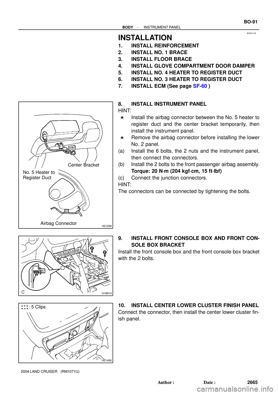
HINT:
�Install the airbag connector between the No. 5 heater to
register duct and the center bracket temporarily, then
install the instrument panel.
�Remove the airbag connector before installing the lower
No. 2 panel.
(a) Install the 6 bolts, the 2 nuts and the instrument panel,
then connect the connectors.
(b) Install the 2 bolts to the front passenger airbag assembly.
Torque: 20 N´m (204 kgf´cm, 15 ft´lbf)
(c) Connect the junction connectors.
HINT:
The connectors can be connected by tightening the bolts.
9. INSTALL FRONT CONSOLE BOX AND FRONT CON-
SOLE BOX BRACKET
Install the front console box and the front console box bracket
with the 2 bolts.
10. INSTALL CENTER LOWER CLUSTER FINISH PANEL
Connect the connector, then install the center lower cluster fin-
ish panel.
Page 427 of 3115
BO1JO-03
H04871
H04872
H05218
- BODYLOWER BACK DOOR
BO-29
2603 Author�: Date�:
2004 LAND CRUISER (RM1071U)
ADJUSTMENT
1. ADJUST DOOR IN FORWARD/REARWARD AND VER-
TICAL DIRECTIONS
Loosen the door side hinge bolts to adjust.
Torque: 28 N´m (286 kgf´cm, 21 ft´lbf)
2. ADJUST DOOR IN LEFT/RIGHT AND VERTICAL
DIRECTIONS
Loosen the body side hinge bolts and nut to adjust.
Torque: 31 N´m (316 kgf´cm, 23 ft´lbf)
3. ADJUST DOOR LOCK STRIKER
(a) Check that the door fit and door linkages are adjusted cor-
rectly.
(b) Using a torx wrench, loosen the door lock striker mounting
screws.
Torx wrench: T40 (Part No. 09042-00020 or locally
manufactured tool)
Torque: 11.5 N´m (117 kgf´cm, 8 ft´lbf)
(c) Using a plastic hammer, tap the striker to adjust it.
Page 428 of 3115
BO1JM-03
H21440
Back Door Lock
Control Cable
Back Door Inside Handle
Spacer
Upper Back Door Striker
Back Door Lock Control
Back Door Lock
Control Cable
Door Lock Striker
Tail Gate Stay
Rear Light Assembly
Service Hole Cover
Back Door Trim Torsion Bar Guide
Lower Torsion BarRear Mat Set Plate Door Lock Striker
Tail Gate Stay
Rear Light Assembly
Service Hole Cover
Back Door Hinge
Clip
Key Cylinder
28 (286, 21)
11.5 (117, 8)
x 5
: Specified torqueN´m (kgf´cm, ft´lbf) Back Door Hinge
5.0 (51, 44 in.´lbf)
11.5 (117, 8)
18.5 (189, 14)
18.5 (189, 14)
5.0 (51, 44 in.´lbf)
31 (316, 23)
28 (286, 21)
31 (316, 23)
5.0 (51, 44 in.´lbf)
18.5 (189, 14)
5.0 (51, 44 in.´lbf)
18.5 (189, 14)
11.5 (117, 8)
BO-26
- BODYLOWER BACK DOOR
2600 Author�: Date�:
2004 LAND CRUISER (RM1071U)
LOWER BACK DOOR
COMPONENTS
Page 429 of 3115

BO217-02
H05258
H04862
: 16 Clips
H04869
H04863
H04864
- BODYLOWER BACK DOOR
BO-27
2601 Author�: Date�:
2004 LAND CRUISER (RM1071U)
DISASSEMBLY
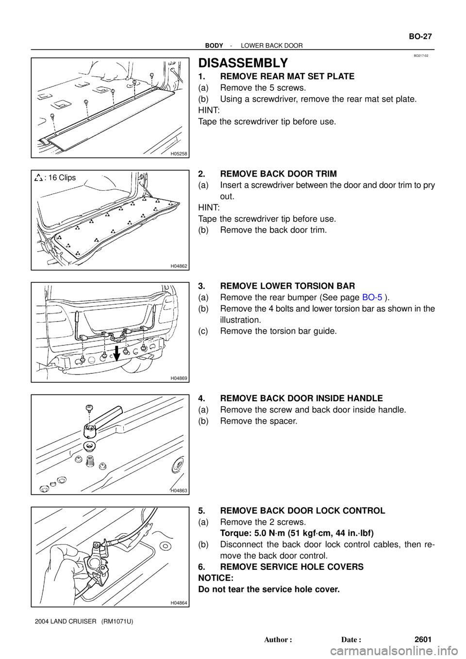
1. REMOVE REAR MAT SET PLATE
(a) Remove the 5 screws.
(b) Using a screwdriver, remove the rear mat set plate.
HINT:
Tape the screwdriver tip before use.
2. REMOVE BACK DOOR TRIM
(a) Insert a screwdriver between the door and door trim to pry
out.
HINT:
Tape the screwdriver tip before use.
(b) Remove the back door trim.
3. REMOVE LOWER TORSION BAR
(a) Remove the rear bumper (See page BO-5).
(b) Remove the 4 bolts and lower torsion bar as shown in the
illustration.
(c) Remove the torsion bar guide.
4. REMOVE BACK DOOR INSIDE HANDLE
(a) Remove the screw and back door inside handle.
(b) Remove the spacer.
5. REMOVE BACK DOOR LOCK CONTROL
(a) Remove the 2 screws.
Torque: 5.0 N´m (51 kgf´cm, 44 in.´lbf)
(b) Disconnect the back door lock control cables, then re-
move the back door control.
6. REMOVE SERVICE HOLE COVERS
NOTICE:
Do not tear the service hole cover.
Page 430 of 3115

H04865
H04866
H04867
H04868
H04870
BO-28
- BODYLOWER BACK DOOR
2602 Author�: Date�:
2004 LAND CRUISER (RM1071U)
7. REMOVE KEY CYLINDER
(a) Disconnect the connector.
(b) Remove the clip and key cylinder.
8. REMOVE BACK DOOR LOCK
(a) Disconnect the control cable from the clamp.
(b) Using a torx wrench, remove the 3 screws and back door
lock.
Torx wrench: T30 (Part No. 09042-00010 or locally
manufactured tool)
Torque: 5.0 N´m (51 kgf´cm, 44 in.´lbf)
HINT:
At the time of reassembly, please refer to the following item.
Apply MP grease to the rotating parts of the door lock.
(c) Employ the same manner described above to the other
side.
9. REMOVE REAR LIGHT ASSEMBLY
(a) Disconnect the connector.
(b) Remove the 2 nuts.
(c) Using a screwdriver, remove the rear light assembly.
HINT:
Tape the screwdriver tip before use.
(d) Employ the same manner described above to the other
side.
10. REMOVE TAIL GATE STAY
(a) Using a torx wrench, remove the 2 screws and tail gate
stay.
Torx wretch: T30 (Part No. 09042-00010 or locally
manufactured tool)
Torque: 18.5 N´m (189 kgf´cm, 14 ft´lbf)
(b) Employ the same manner described above to the other
side.
Page 434 of 3115

BO4IW-01
H05257
: 5 Clips
H05258
H05259
H07941
11 Clips BO-62
- BODYQUARTER WINDOW GLASS
2636 Author�: Date�:
2004 LAND CRUISER (RM1071U)
REMOVAL
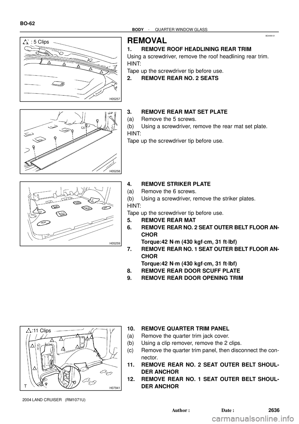
1. REMOVE ROOF HEADLINING REAR TRIM
Using a screwdriver, remove the roof headlining rear trim.
HINT:
Tape up the screwdriver tip before use.
2. REMOVE REAR NO. 2 SEATS
3. REMOVE REAR MAT SET PLATE
(a) Remove the 5 screws.
(b) Using a screwdriver, remove the rear mat set plate.
HINT:
Tape up the screwdriver tip before use.
4. REMOVE STRIKER PLATE
(a) Remove the 6 screws.
(b) Using a screwdriver, remove the striker plates.
HINT:
Tape up the screwdriver tip before use.
5. REMOVE REAR MAT
6. REMOVE REAR NO. 2 SEAT OUTER BELT FLOOR AN-
CHOR
Torque:42 N´m (430 kgf´cm, 31 ft´lbf)
7. REMOVE REAR NO. 1 SEAT OUTER BELT FLOOR AN-
CHOR
Torque:42 N´m (430 kgf´cm, 31 ft´lbf)
8. REMOVE REAR DOOR SCUFF PLATE
9. REMOVE REAR DOOR OPENING TRIM
10. REMOVE QUARTER TRIM PANEL
(a) Remove the quarter trim jack cover.
(b) Using a clip remover, remove the 2 clips.
(c) Remove the quarter trim panel, then disconnect the con-
nector.
11. REMOVE REAR NO. 2 SEAT OUTER BELT SHOUL-
DER ANCHOR
12. REMOVE REAR NO. 1 SEAT OUTER BELT SHOUL-
DER ANCHOR