Page 3054 of 3115
SA149-05
F05160
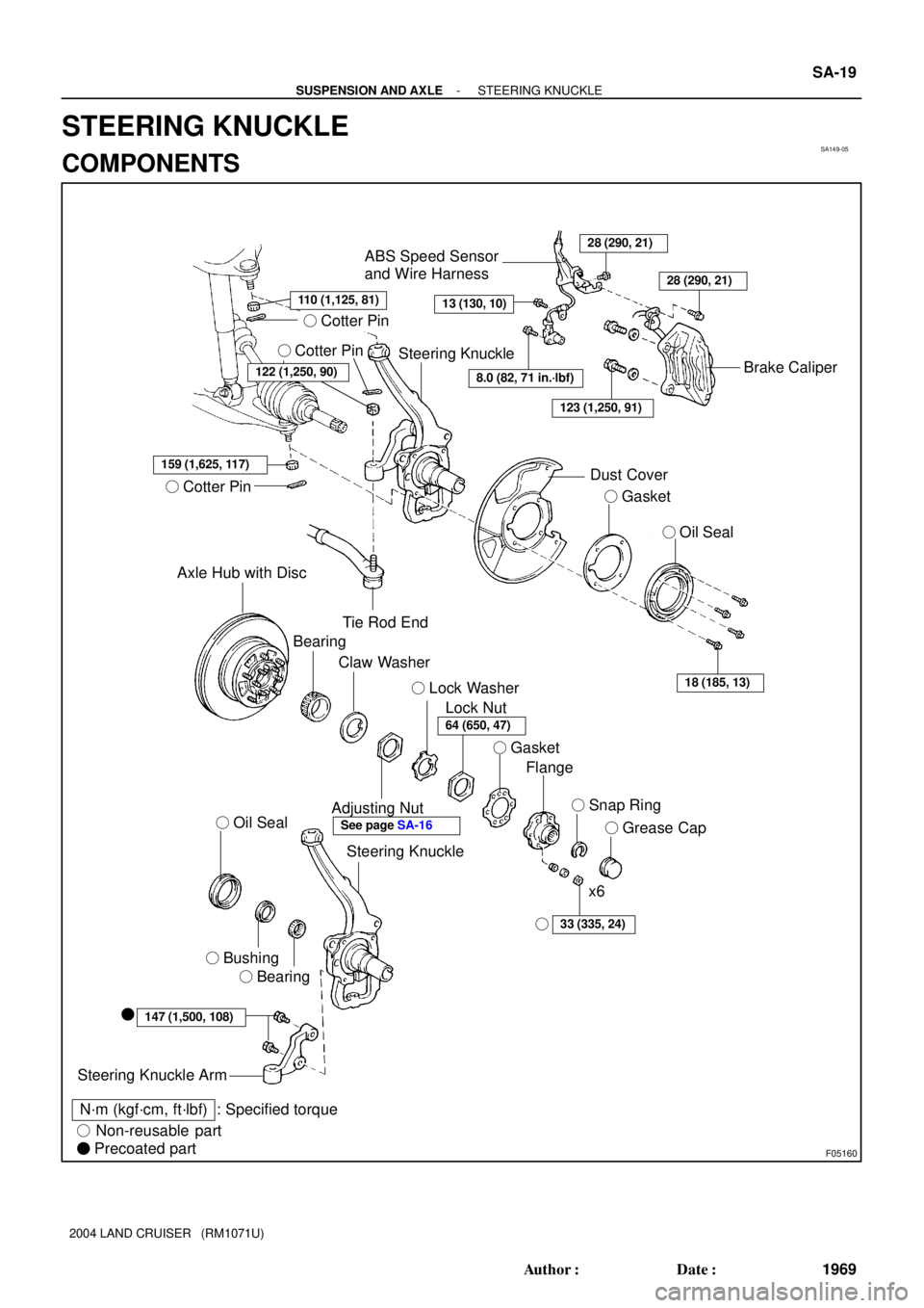
� Cotter Pin
� Cotter Pin
159 (1,625, 117)
� Cotter Pin
Axle Hub with Disc
Tie Rod End
ABS Speed Sensor
and Wire Harness28 (290, 21)
13 (130, 10)
Brake Caliper
Dust Cover
� Gasket
� Oil Seal
18 (185, 13)
Bearing
Claw Washer
Adjusting Nut
Lock Nut � Lock Washer
� Gasket
Flange
� Snap Ring
� Grease Cap
33 (335, 24)
x6
Steering Knuckle
� Oil Seal
� Bushing
� Bearing
147 (1,500, 108)�
Steering Knuckle Arm
N´m (kgf´cm, ft´lbf) : Specified torque
� Non-reusable part
� Precoated part
Steering Knuckle
8.0 (82, 71 in.´lbf)
123 (1,250, 91)
122 (1,250, 90)
28 (290, 21)
�
64 (650, 47)
See page SA-16
110 (1,125, 81)
- SUSPENSION AND AXLESTEERING KNUCKLE
SA-19
1969 Author�: Date�:
2004 LAND CRUISER (RM1071U)
STEERING KNUCKLE
COMPONENTS
Page 3056 of 3115

INSTALLATION
1. INSTALL STEERING KNUCKLE
(a) Apply synthetic oil and lithium")
SA14D-04
F04405
F04372
A
BC SA-24
- SUSPENSION AND AXLESTEERING KNUCKLE
1974 Author�: Date�:
2004 LAND CRUISER (RM1071U)
INSTALLATION
1. INSTALL STEERING KNUCKLE
(a) Apply synthetic oil and lithium soap base chassis grease,
NLGI No. 1 to the drive shaft.
(b) Support the lower suspension arm with jack and connect
the steering knuckle to the lower suspension arm.
NOTICE:
Be careful not to damage the oil seal.
(c) Temporarily install the nut to lower suspension arm.
(d) Raise up the lower suspension arm using a jack and
install the steering knuckle to the upper suspension arm
with a nut.
Torque: 110 N´m (1,125 kgf´cm, 81 ft´lbf)
(e) Install a new cotter pin.
If the holes for the cotter pin are not aligned, tighten the nut fur-
ther up to 60°.
(f) Torque the nut of the lower suspension arm.
Torque: 159 N´m (1,625 kgf´cm, 117 ft´lbf)
(g) Install a new cotter pin.
2. CONNECT TIE ROD END
(a) Connect the tie rod end to steering knuckle with nut.
Torque: 122 N´m (1,250 kgf´cm, 91 ft´lbf)
(b) Install a new cotter pin.
If the holes for the cotter pin are not aligned, tighten the nut fur-
ther up to 60°.
3. CONNECT ABS SPEED SENSOR AND WIRE HAR-
NESS
Install the wire harness and 3 bolts.
Torque:
A: 8.0 N´m (82 kgf´cm, 71 in.´lbf)
B: 13 N´m (130 kgf´cm, 10 ft´lbf)
C: 28 N´m (290 kgf´cm, 21 ft´lbf)
4. INSTALL DUST COVER, GASKET AND OIL SEAL
Install the dust cover, new gasket and oil seal with the 4 bolts.
Torque: 18 N´m (185 kgf´cm, 13 ft´lbf)
5. INSTALL FRONT AXLE HUB (See page SA-16)
Page 3057 of 3115
SA14C-04
F04348
SST
F04349
SST
- SUSPENSION AND AXLESTEERING KNUCKLE
SA-23
1973 Author�: Date�:
2004 LAND CRUISER (RM1071U)
REASSEMBLY
1. INSTALL BEARING AND BUSHING
(a) Using SST and a press, install a new bearing and bush-
ing.
SST 09950-60010 (09951-00540),
09950-70010 (09951-07100)
(b) Apply synthetic oil and lithium soap base chassis grease,
NLGI No. 1 to the steering knuckle inner side of the bush-
ing.
2. INSTALL OIL SEAL
(a) Using SST and a press, install a new oil seal.
SST 09950-60020 (09951-00910),
09950-70010 (09951-07100)
(b) Coat the lip of the oil seal with MP grease.
3. INSTALL STEERING KNUCKLE ARM
(a) Clean the threads of the 2 bolts and steering knuckle with
toluene or trichloroethylene.
(b) Apply sealant to the bolt threads.
Sealant:
Part No. 08833-00070, THREE BOND 1324
or equivalent
(c) Install the steering knuckle arm with the 2 bolts.
Torque: 147 N´m (1,500 kgf´cm, 108 ft´lbf)
Page 3065 of 3115
TR06J-02
D04344
Front Drive
Gear Piece
� Snap RingFront Taper
Roller BearingNeedle Roller BearingClutch Hub High Speed Output
Gear Bushing High Speed
Output Gear
Rear Taper
Roller Bearing
x12
Differential
Rear Case
Pinion ShaftRear Side
Gear
: Specified torqueThrust Washer
Front Side Gear
N´m (kgf´cm, ft´lbf)Straight Pin
Low GearStraight PinHigh and Low
Clutch Sleeve
Thrust Washer
Thrust Washer Thrust Washer
� Non-reusable partPinion Gear
Differential
Front Case
See page TR-31
Pinion Gear
- TRANSFERCENTER DIFFERENTIAL
TR-27
1915 Author�: Date�:
2004 LAND CRUISER (RM1071U)
CENTER DIFFERENTIAL
COMPONENTS
Page 3070 of 3115

(b) Using a dial indicator, measure the front case backlash.
HINT:
Push t")
TF0917
TF0920
Q00534
SST
Q00547
SST
SST
TR-32
- TRANSFERCENTER DIFFERENTIAL
1920 Author�: Date�:
2004 LAND CRUISER (RM1071U)
(b) Using a dial indicator, measure the front case backlash.
HINT:
Push the pinion shaft.
Maximum backlash: 0.05 mm (0.0020 in.)
If the backlash is not within the specification, replace the thrust
washer with one of the correct size and reinstall the thrust wash-
er.
Thickness mm (in.)Thickness mm (in.)
1.70 (0.0669)2.45 (0.0965)
1.85 (0.0728)2.60 (0.1024)
2.00 (0.0787)2.75 (0.1083)
2.15 (0.0846)2.90 (0.1142)
2.30 (0.0906)3.05 (0.1201)
(c) In the same way, measure the rear case backlash.
4. INSTALL STRAIGHT PIN TO PINION SHAFT
5. INSTALL REAR SIDE GEAR AND THRUST WASHER
6. INSTALL DIFFERENTIAL REAR CASE
(a) Install the differential rear case and 12 set bolts.
Torque: 88 N´m (900 kgf´cm, 65 ft´lbf)
(b) Turn the pinion gear.
(c) Loosen the 12 rear case set bolts.
(d) Torque the 12 rear case set bolts.
Torque: 98 N´m (1,000 kgf´cm, 72 ft´lbf)
7. INSTALL REAR TAPER ROLLER BEARING
Using SST and a press, install the rear taper roller bearing.
SST 09316-12010
8. INSTALL CLUTCH HUB
Using SST and a press, install the clutch hub.
SST 09316-12010, 09316-60011 (09316-00011)
Page 3090 of 3115
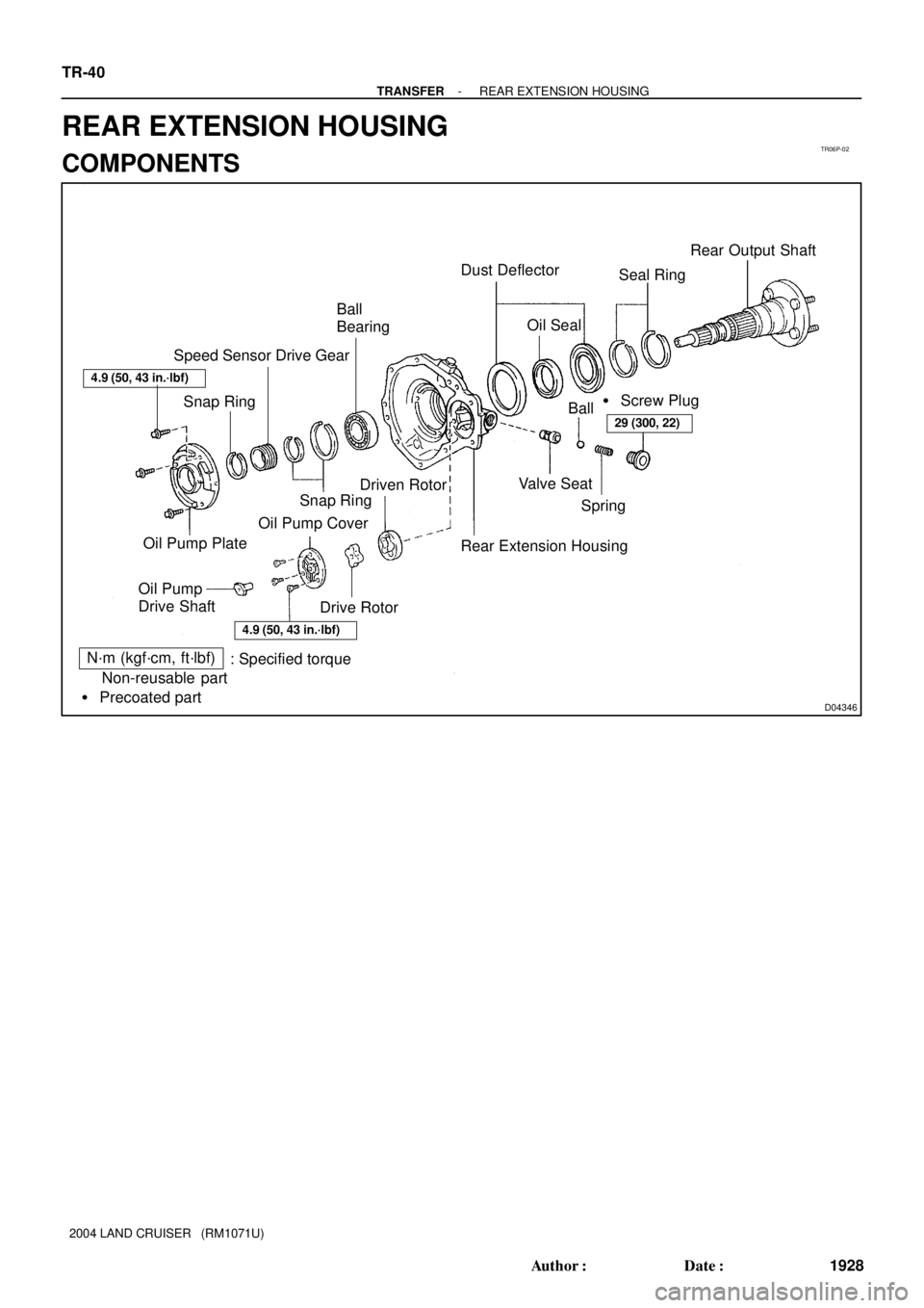
TR06P-02
D04346
Ball
Bearing� Dust Deflector
Seal RingRear Output Shaft
� Screw Plug
Ball
Rear Extension Housing Driven Rotor Speed Sensor Drive Gear
Drive Rotor Oil Pump CoverSpring Valve Seat
4.9 (50, 43 in.´lbf)
29 (300, 22)
� Oil Seal
� Snap Ring Snap Ring
Oil Pump
Drive ShaftOil Pump Plate
N´m (kgf´cm, ft´lbf)
: Specified torque
� Non-reusable part
� Precoated part
4.9 (50, 43 in.´lbf)
TR-40
- TRANSFERREAR EXTENSION HOUSING
1928 Author�: Date�:
2004 LAND CRUISER (RM1071U)
REAR EXTENSION HOUSING
COMPONENTS
Page 3095 of 3115
TF0969
SST
TF0958
D04353
- TRANSFERREAR EXTENSION HOUSING
TR-45
1933 Author�: Date�:
2004 LAND CRUISER (RM1071U)
4. INSTALL REAR OUTPUT SHAFT
(a) Using SST and a press, install the rear output shaft.
SST 09316- 20011, 09316- 60011 (09316- 00011,
09316-00031)
(b) Install the 2 seal rings to the rear output shaft.
(c) Select a snap ring that will allow the minimum axial play.
MarkThickness mm (in.)
11.95 (0.0768)
22.05 (0.0807)
32.15 (0.0847)
42.25 (0.0886)
(d) Using a snap ring expander, install a new snap ring.
5. INSTALL SPEED SENSOR DRIVE GEAR
(a) Install the speed sensor drive gear.
(b) Using a snap ring expander, install the snap ring.
6. INSTALL OIL PUMP PLATE
(a) Install the oil pump plate.
(b) Install and torque the 3 bolts.
Torque: 4.9 N´m (50 kgf´cm, 43 in.´lbf)
Page 3096 of 3115
Q08384
TF0977
Q00529
TR-46
- TRANSFERREAR EXTENSION HOUSING
1934 Author�: Date�:
2004 LAND CRUISER (RM1071U)
7. INSTALL VALVE SEAT, BALL, SPRING AND SCREW
PLUG
(a) Apply gear oil to the ball.
(b) Install the valve seat, ball and spring.
(c) Apply liquid sealer to the screw plug threads.
Sealant:
Part No. 08833-00080, THREE BOND 1344, LOCTITE
242 or equivalent
(d) Using a hexagon wrench, install and torque the screw
plug.
Torque: 29 N´m (300 kgf´cm, 22 ft´lbf)
8. INSTALL DRIVEN ROTOR
(a) Apply gear oil to the driven rotor.
(b) Install the driven rotor.
9. INSTALL DRIVE ROTOR
(a) Apply gear oil to the drive rotor.
(b) Install the drive rotor.
HINT:
Align the alignment marks.
10. INSTALL OIL PUMP COVER
(a) Install the oil pump cover.
(b) Using a torx socket wrench (T30), install and torque the
3 screws.
Torque: 4.9 N´m (50 kgf´cm, 43 in.´lbf)
NOTICE:
Align the oil hole of the rear extension housing and oil
groove end of the oil pump cover.
11. INSTALL OIL PUMP DRIVE SHAFT