Page 365 of 1463

OM600 ENGINE MECHANICAL 1B3-63
TIMING CASE COVER
Preceding Work : Removal of the cooling fan
Rmoval of the V-belt tensioning device
Removal of the vibration damper and hub
Removal of the alternator
1 Bolt............................................................10Nm
2 Cylinder Head Cover
3 Gasket ................................................... Replace
4 Socket Bolt................................................25Nm
5 Fuel Filter
6 Square Nut
7 Oil Pan
8 Socket Bolt................................................10Nm
9 Bolt.................................................... M6 : 10Nm
M8 : 23Nm
10 Power Steering Pump
11 Bolt
12 Belt Pulley1 3 Bolt............................................................32Nm
14 Timing Case Cover
1 5 Bolt............................................................23Nm
16 Alternator Bracket
1 7 Bolt............................................................45Nm
1 8 Bolt............................................................25Nm
1 9 Bolt............................................................10Nm
20 Closing Cover
21 Socket Bolt................................................23Nm
22 Guide Pulley
2 3 Bolt.............................................................. 9Nm
24 Guide Pulley Bracket
25 Nut .............................................................23Nm
Page 394 of 1463

1B3-92 OM600 ENGINE MECHANICAL
28. Remove the connecting rod bearing cap.
29. Install the piston.
30. Rotate the crankshaft by hand and check whether it rotates
smoothly.
31. If the bearings are damaged,
- replace the oil presser relief valve.
- clean the oil pump and oil filter housing carefully and
replace the hose if necessary.
Notice
After assembling the engine, check the camshaft timing,
adjust the start of fuel injection and check the TDC sensor
bracket setting.
32. Fill oil and run the engine and then check the oil pressure
and oil level.
Notice
Install the original oil filter element and then change the
engine oil and oil filter element after 1,000 - 1,500km. 27. Measure the radial clearance (L) of the connecting rod
bearing.
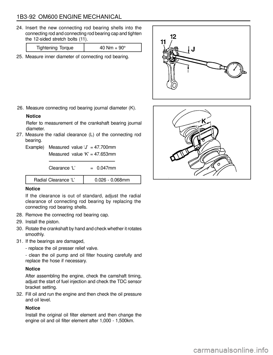
Example)Measured value ‘J’ = 47.700mm
Measured value ‘K’ = 47.653mm
Clearance ‘L’ = 0.047mm
Radial Clearance ‘L’ 0.026 - 0.068mm
Notice
If the clearance is out of standard, adjust the radial
clearance of connecting rod bearing by replacing the
connecting rod bearing shells. 26. Measure connecting rod bearing journal diameter (K).
Notice
Refer to measurement of the crankshaft bearing journal
diameter.
24. Insert the new connecting rod bearing shells into the
connecting rod and connecting rod bearing cap and tighten
the 12-sided stretch bolts (11).
25. Measure inner diameter of connecting rod bearing.
Tightening Torque 40 Nm + 90°
Page 471 of 1463
OM600 ENGINE MECHANICAL 1B3-169
OIL FILTER
1 Nut ............................................................ 25 Nm
2 Oil Filter..................................................... Cover
3 O-Ring ................................................... Replace
4 Oil Filter...............Element Replace If necessary
5 Oil Filter Housing6 Bolt (M8)....................................................10Nm
7 Oil Pressure Switch
8 Gasket
9 Bolt........................................................... 25 Nm
Page 472 of 1463
1B3-170 OM600 ENGINE MECHANICAL
Removal & Installation Procedure
1. Remove the oil filter cover and then drain the oil.
2. Remove the oil pressure switch line.
3. Remove the oil filter housing.
4. Clean the sealing surface.
5. Installation should follow the removal procedure in the
reverse order.
Page 475 of 1463
OM600 ENGINE MECHANICAL 1B3-173
Oil Filter
a From Oil Pump
b To Main Oil Gallery
c To Oil Pan
Page 872 of 1463
3A-4 FRONT DRIVE AXLE
AUTO-LOCKING HUB
1 Cap
2 Filter
3 Vacuum Diaphragm
4 Diaphragm Retainer
5 Piston
6 Bolt (M10)
7 Lock Washer
8 O-ring
9 Retaining Ring
10 Clutch Ring11 Body
12 Return Spring
13 Bearing
14 O-ring
15 Retaining Ring
16 Inner Drive Gear
17 Oil Seal
18 Oil Seal Race
19 Axle Retaining Ring
Page 1103 of 1463

5A-126 AUTOMATIC TRANSMISSION
Oil Filter and Pan Assembly
Notice
1. Replace the filter whenever rebuilding a transmission where a significant amount of mechanical damage has
occurred.
2. To aid the assembly of the pan gasket, use a small amount of Vaseline at the pan/gasket interface. This ensures
that the gasket remains on the pan ridge. Do not over torque pan bolts as this may distort the pan and cause
leaks.
3. Ensure that the internal line pressure plus in the valve body is fitted.
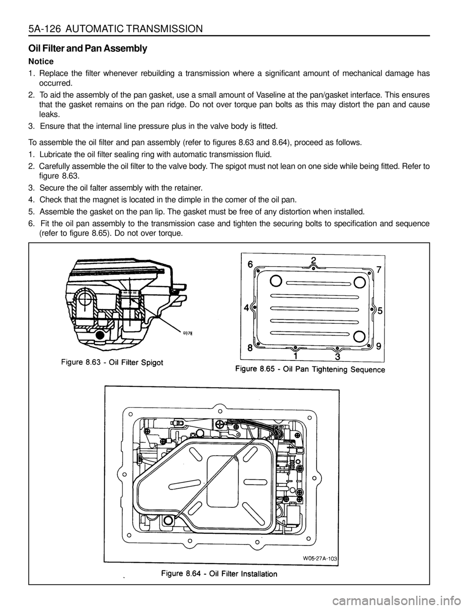
To assemble the oil filter and pan assembly (refer to figures 8.63 and 8.64), proceed as follows.
1. Lubricate the oil filter sealing ring with automatic transmission fluid.
2. Carefully assemble the oil filter to the valve body. The spigot must not lean on one side while being fitted. Refer to
figure 8.63.
3. Secure the oil falter assembly with the retainer.
4. Check that the magnet is located in the dimple in the comer of the oil pan.
5. Assemble the gasket on the pan lip. The gasket must be free of any distortion when installed.
6. Fit the oil pan assembly to the transmission case and tighten the securing bolts to specification and sequence
(refer to figure 8.65). Do not over torque.
Page 1255 of 1463

5D2-48 TRANSFER CASE (TOD)
6. Install the front planet to the sun gear and input shaft.
Install the internal snap ring to the planetary carrier.
7. Place the tanged snap ring in the case. Expand snap ring
with snap ring pliers and install planetary carrier assembly.
Check installation by holding the case and carefully tapping
the face of the input shaft against a wooden block to make
sure the snap ring is installed.
8. Remove all traces of gasket sealant from the front case
and mounting adapter mating surfaces. Install a bead of
gasket sealant on the surface of the front case.
9. Install the high-low shift fork and high-low collar as an
assembly into the front planet.
Notice
Make sure that the nylon wear pads are installed on the
shift fork and snapped securely into place.
12 Rear Output Shaft
13 Oil Strainer
14 Coupling Hose
15 Hose Clamp
16 Pump Body
10. If new pump is used, align the flat of the output shaft and
the flat of the pump. Slide the pump onto the output shaft.
lDo not disassemble oil pump. It is serviced only as an
assembly. Check the pump to make sure the pump
rotates freely.
lDo not remove the plastic insert from the bore of the
new pump. Discard it after it slides out during pump
installation to the rear output shaft.
lWhile turning the output shaft, prime the pump through
the oil filter pickup tube or housing inlet hole with clean
Automatic Transmission Fluid or equivalent.
11. Inspect the outside surfaces and bore of the oil pump. If
there is no discoloration in the pump housing, gear or cover,
and the pump bore and the lube holes of the output shaft
show evidence of oil, the pump is working.