Page 764 of 1463
OM600 ENGINE CONTROLS 1F3-35
INJECTION TIMING DEVICE
Preceding Work : Removal of injection timing device
1 Cam Sprocket........................................... Check
2 Bushing .................................................... Check
3 Governor Weights4 Segment Flange and Drive Hub
5 Compression Springs
Page 765 of 1463
1F3-36 OM600 ENGINE CONTROLS
Disassembly & Assembly
1. Remove the governor weights (3).
2. Pull out the compression springs (5) and cam sprocket (1)
from the segment flange (4).
3. Knock out the bushing with a proper drift.
4. Installation should follow the removal procedure in the
reverse order.
Page 865 of 1463
2E-4 TIRES AND WHEELS
COMPONENT LOCATOR
WHEEL AND TIRE
1 Wheel Bolts.................Steel Wheel : 80-120 Nm
..........................Aluminium Wheel : 110-130 Nm
2 Steel Wheel
3 Aluminium Wheel4 Tire
5 Steel Wheel Weight Balance
6 Hub Cap
Page 867 of 1463
2E-6 TIRES AND WHEELS
4. Tire pressure inspection.
lTire pressure.
lCheck tread contact with road.
Notice
lIf underinflated, tire may come away from the wheel
during rapid steering.
lAn overinflated tire will cause a hard riding and uneven
wear.
Front & Rear
(P235/75R15)2.1kg/cm (30PSI)2
5. Wheel balance.
lBalance weights should be on each side. When the wheel
is out of balance or a tire has been repaired, be sure to
balance the wheel again.
lIf total weight is over 150g, readjust the balance by
reinstalling the tire on the wheel.
lBalance weight should not protrude from the wheel rim
over 3mm.
lFor aluminum wheel, use aluminum wheel balance weight
only.
Page 868 of 1463
TIRES AND WHEELS 2E-7
lTo correct unbalance, install equal weights 180° opposite
each other, one on the inside of the wheel and one on
the outside, at the point of unbalance.
lBalance Weight
6. Cautions for installation and removal.
lClean the mounting surfaces of hub and wheel.
lDo not apply grease or oil on the nuts and bolts (It will
cause looseness and poor tightening).
lUsing a jack, lift up the tire about 3cm from the ground.
lTighten nuts in a criss-cross pattern 2-3 times.
10g
0.4oz20g
0.7oz30g
1.10oz40g
1.40oz50g
1.80oz60g
2.1oz
Steel : 80 - 120Nm
Aluminium : 110 - 130NmTighten Torque
Page 897 of 1463
PROPELLER SHAFT 3C-7
Installation Procedure
Clean the disassembled parts and replace them if damaged.
1. Align the alignment marks of the yoke and assemble the
spider, bearing and snap ring.
2. Apply grease to the inner of the bearing cap of the needle
roller bearing and assemble the needle roller.
Grease EP #2
6. Possible cause of vibration.
lDrift away of balance weights.
lExcessive runout of the propeller shaft.
lUsing normal bolts.
lExcessive wear of the universal joint.
lSticks in sleeve joint.
lDrive angle changes in universal joints or cross causes
vibration and can be detected around 60~100 km/h. 5. Universal joint starting torque.
Starting Torque 3 - 8 kglcm
Page 1082 of 1463

AUTOMATIC TRANSMISSION 5A-105
21. Holding the cylinder horizontal, install the sleeve and clutch
plate assembly into the cylinder, with the crest of one wave
of the washer In line with one of the holes in the outside of
the cylinder, until the sleeve contacts the C2 wave washer.
22. Check the C4 clutch pack clearance using special tool No.
0555-331900. Refer to figure 8.25.
Notice
With the C2 wave spring compressed, and the clutch Pack
supporting a 2 k9 weight, the dimension from the underside
of the C2 pressure plate to the selective steel is to be
between 1.4- 1.8 mm. If the clutch is to be gauged from
the top of the pressure plate, then the dimension is to be
the actual thickness of the pressure plate plus 1.4-1.8 mm.
23. Use selective plates to achieve the correct specification. If
new friction plates are being fitted, remove the clutch pack
and soak the friction plates in ATF for a minimum of 5
minutes prior to reassembly.
Notice
The clutch pack clearance must be taken before the
elements are soaked in Automatic Transmission Fluid
(ATF).
24. Reassemble the sleeve and clutch pack into the cylinder.
Observe the alignment of the wave washer to the hole in
the cylinder.
25. Install the C2 clutch plates in the cylinder in the following
sequence:
lFriction disc
lSteel plate
lFriction disc
lSteel plate
lSteel plate - 0574-000001, 0574-000003,
0574-000004, 0574-000005, 0574-000020,
0574-000021, or friction disc -0574-000002
lSteel plate (selective)
lFriction disc
lSteel plate (selective)
lFriction disc
Page 1083 of 1463

5A-106 AUTOMATIC TRANSMISSION
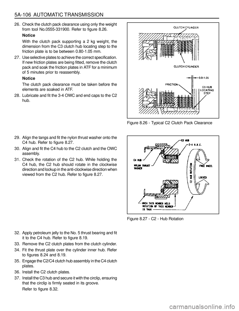
29. Align the tangs and fit the nylon thrust washer onto the
C4 hub. Refer to figure 8.27.
30. Align and fit the C4 hub to the C2 clutch and the OWC
assembly.
31. Check the rotation of the C2 hub. While holding the
C4 hub, the C2 hub should rotate in the clockwise
direction and lockup in the anti-clockwise direction when
viewed from the C2 hub. Refer to figure 8.27.
Figure 8.27 - C2 - Hub Rotation
32. Apply petroleum jelly to the No. 5 thrust bearing and fit
it to the C4 hub. Refer to figure 8.19.
33. Remove the C2 clutch plates from the clutch cylinder.
34. Fit the thrust plate over the cylinder inner hub. Refer
to figures 8.24 and 8.19.
35. Engage the C2/C4 clutch hub assembly in the C4 clutch
plates.
36. Install the C2 clutch plates.
37. Install the C3 hub and secure it with the circlip, ensuring
that the circlip is firmly seated in its groove.
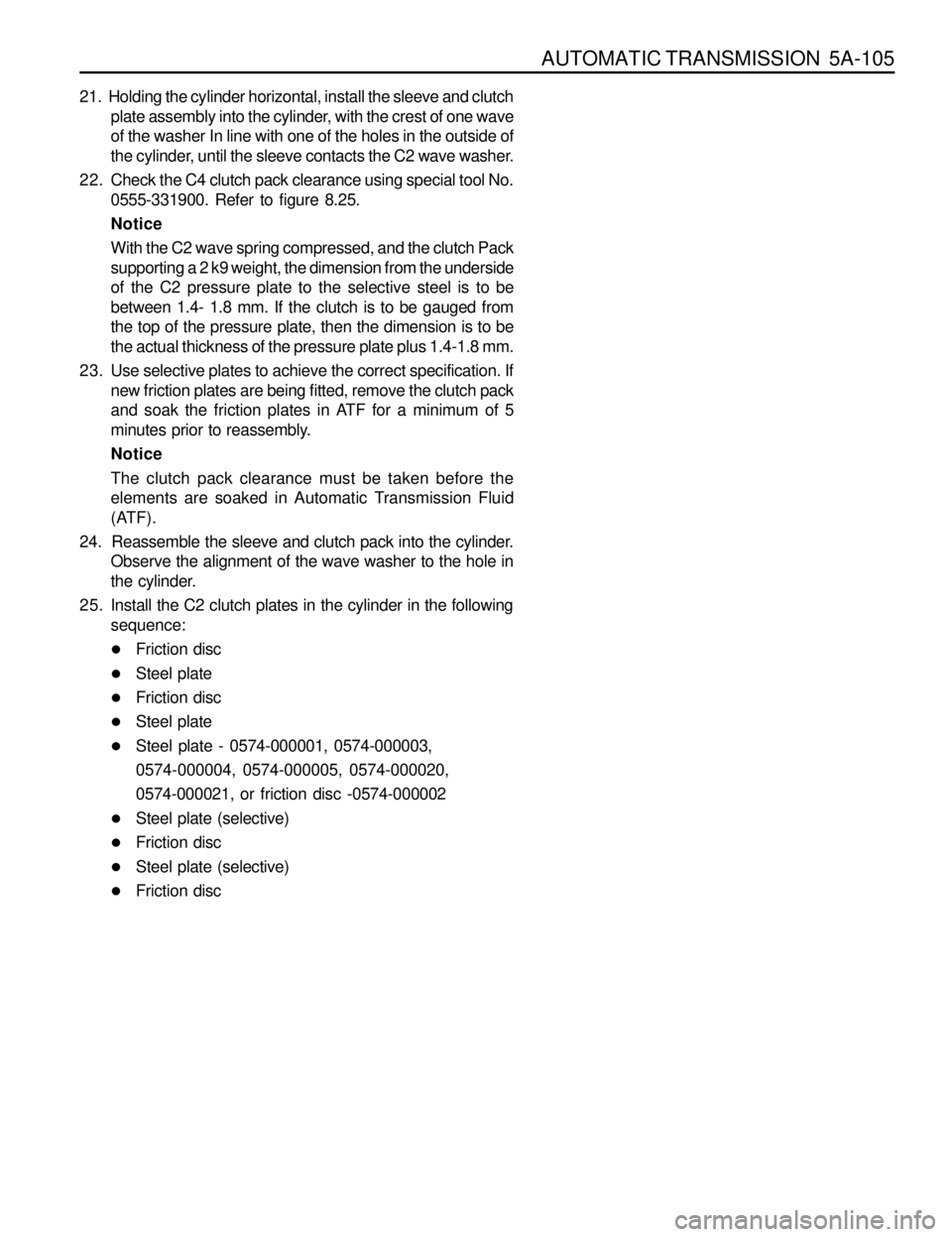
Refer to figure 8.32.Figure 8.26 - Typical C2 Clutch Pack Clearance 26. Check the clutch pack clearance using only the weight
from tool No.0555-331900. Refer to figure 8.26.
Notice
With the clutch pack supporting a 2 kg weight, the
dimension from the C3 clutch hub locating step to the
friction plate is to be between 0.80-1.05 mm.
27. Use selective plates to achieve the correct specification.
If new friction plates are being fitted, remove the clutch
pack and soak the friction plates in ATF for a minimum
of 5 minutes prior to reassembly.
Notice
The clutch pack clearance must be taken before the
elements are soaked in ATF.
28. Lubricate and fit the 3-4 OWC and end caps to the C2
hub.