1998 OPEL FRONTERA ignition
[x] Cancel search: ignitionPage 5654 of 6000
6E–225 4JX1–TC ENGINE DRIVEABILITY AND EMISSIONS
General Description
(ECM and Sensors)
57X Reference ECM Input
The engine control module (ECM) uses this signal from
the crankshaft position (CKP) sensor to calculate engine
RPM and crankshaft position at all engine speeds. The
ECM also uses the pulses on this circuit to initiate injector
pulses. If the ECM receives no pulses on this circuit, DTC
P0337 will set. The engine will not start and run without
using the 57X reference signal.
A/C Request Signal
This signal tells the ECM when the A/C mode is selected
at the A/C control head.
Refer to
A/C Clutch Circuit Diagnosis for A/C wiring
diagrams and diagnosis for the A/C electrical system.
Crankshaft Position (CKP) Sensor
The crankshaft position (CKP) sensor provides a signal
used by the engine control module (ECM) to calculate the
ignition sequence. The CKP sensor initiates the 57X
reference pulses which the ECM uses to calculate RPM
and crankshaft position.
Refer to
Electronic Ignition System for additional
information.
Camshaft Position (CMP) Sensor and
Signal
The camshaft position (CMP) sensor sends a CMP signal
to the ECM. The ECM uses this signal as a “cylinder
distinction” to trigger the injectors in the power order. If the
ECM detects an incorrect CMP signal while the engine is
running, DTC P0341 will set, and the ECM triggers the
injectors in the power order.
Refer to
DTC P0341.
Engine Coolant Temperature (ECT) Sensor
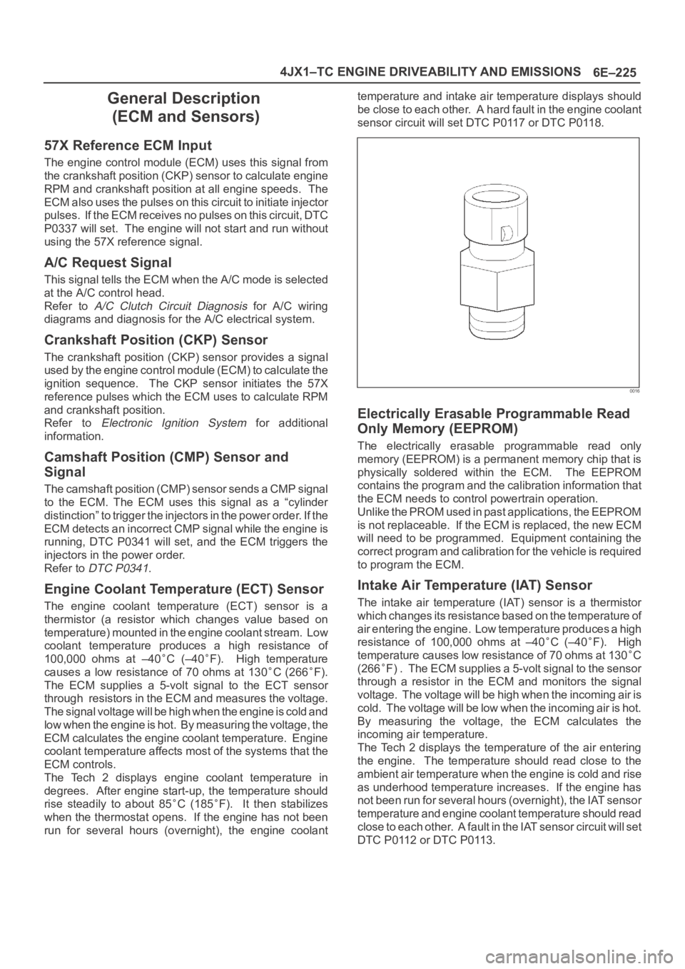
The engine coolant temperature (ECT) sensor is a
thermistor (a resistor which changes value based on
temperature) mounted in the engine coolant stream. Low
coolant temperature produces a high resistance of
100,000 ohms at –40
C (–40F). High temperature
causes a low resistance of 70 ohms at 130
C (266F).
The ECM supplies a 5-volt signal to the ECT sensor
through resistors in the ECM and measures the voltage.
The signal voltage will be high when the engine is cold and
low when the engine is hot. By measuring the voltage, the
ECM calculates the engine coolant temperature. Engine
coolant temperature affects most of the systems that the
ECM controls.
The Tech 2 displays engine coolant temperature in
degrees. After engine start-up, the temperature should
rise steadily to about 85
C (185F). It then stabilizes
when the thermostat opens. If the engine has not been
run for several hours (overnight), the engine coolanttemperature and intake air temperature displays should
be close to each other. A hard fault in the engine coolant
sensor circuit will set DTC P0117 or DTC P0118.
0016
Electrically Erasable Programmable Read
Only Memory (EEPROM)
The electrically erasable programmable read only
memory (EEPROM) is a permanent memory chip that is
physically soldered within the ECM. The EEPROM
contains the program and the calibration information that
the ECM needs to control powertrain operation.
Unlike the PROM used in past applications, the EEPROM
is not replaceable. If the ECM is replaced, the new ECM
will need to be programmed. Equipment containing the
correct program and calibration for the vehicle is required
to program the ECM.
Intake Air Temperature (IAT) Sensor
The intake air temperature (IAT) sensor is a thermistor
which changes its resistance based on the temperature of
air entering the engine. Low temperature produces a high
resistance of 100,000 ohms at –40
C (–40F). High
temperature causes low resistance of 70 ohms at 130
C
(266
F) . The ECM supplies a 5-volt signal to the sensor
through a resistor in the ECM and monitors the signal
voltage. The voltage will be high when the incoming air is
cold. The voltage will be low when the incoming air is hot.
By measuring the voltage, the ECM calculates the
incoming air temperature.
The Tech 2 displays the temperature of the air entering
the engine. The temperature should read close to the
ambient air temperature when the engine is cold and rise
as underhood temperature increases. If the engine has
not been run for several hours (overnight), the IAT sensor
temperature and engine coolant temperature should read
close to each other. A fault in the IAT sensor circuit will set
DTC P0112 or DTC P0113.
Page 5655 of 6000
6E–226
4JX1–TC ENGINE DRIVEABILITY AND EMISSIONS
0018
Manifold Absolute Pressure (MAP) Sensor
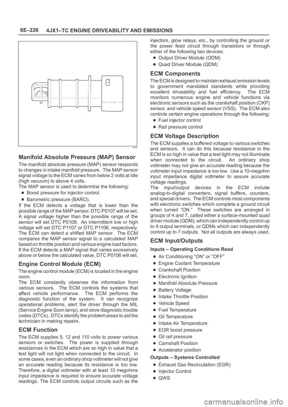
The manifold absolute pressure (MAP) sensor responds
to changes in intake manifold pressure. The MAP sensor
signal voltage to the ECM varies from below 2 volts at idle
(high vacuum) to above 4 volts.
The MAP sensor is used to determine the following:
Boost pressure for injector control.
Barometric pressure (BARO).
If the ECM detects a voltage that is lower than the
possible range of the MAP sensor, DTC P0107 will be set.
A signal voltage higher than the possible range of the
sensor will set DTC P0108. An intermittent low or high
voltage will set DTC P1107 or DTC P1106, respectively.
The ECM can detect a shifted MAP sensor. The ECM
compares the MAP sensor signal to a calculated MAP
based on throttle position and various engine load factors.
If the ECM detects a MAP signal that varies excessively
above or below the calculated value, DTC P0106 will set.
Engine Control Module (ECM)
The engine control module (ECM) is located in the engine
room.
The ECM constantly observes the information from
various sensors. The ECM controls the systems that
affect vehicle performance. The ECM performs the
diagnostic function of the system. It can recognize
operational problems, alert the driver through the MIL
(Service Engine Soon lamp), and store diagnostic trouble
codes (DTCs). DTCs identify the problem areas to aid the
technician in making repairs.
ECM Function
The ECM supplies 5, 12 and 110 volts to power various
sensors or switches. The power is supplied through
resistances in the ECM which are so high in value that a
test light will not light when connected to the circuit. In
some cases, even an ordinary shop voltmeter will not give
an accurate reading because its resistance is too low.
Therefore, a digital voltmeter with at least 10 megohms
input impedance is required to ensure accurate voltage
readings. The ECM controls output circuits such as theinjectors, glow relays, etc., by controlling the ground or
the power feed circuit through transistors or through
either of the following two devices:
Output Driver Module (ODM)
Quad Driver Module (QDM)
ECM Components
The ECM is designed to maintain exhaust emission levels
to government mandated standards while providing
excellent driveability and fuel efficiency. The ECM
monitors numerous engine and vehicle functions via
electronic sensors such as the crankshaft position (CKP)
sensor, and vehicle speed sensor (VSS). The ECM also
controls certain engine operations through the following:
Fuel injector control
Rail pressure control
ECM Voltage Description
The ECM supplies a buffered voltage to various switches
and sensors. It can do this because resistance in the
ECM is so high in value that a test light may not illuminate
when connected to the circuit. An ordinary shop
voltmeter may not give an accurate reading because the
voltmeter input impedance is too low. Use a 10-megohm
input impedance digital voltmeter to assure accurate
voltage readings.
The input/output devices in the ECM include
analog-to-digital converters, signal buffers, counters,
and special drivers. The ECM controls most components
with electronic switches which complete a ground circuit
when turned “ON.” These switches are arranged in
groups of 4 and 7, called either a surface-mounted quad
driver module (QDM), which can independently control up
to 4 output terminals, or QDMs which can independently
control up to 7 outputs. Not all outputs are always used.
ECM Input/Outputs
Inputs – Operating Conditions Read
Air Conditioning “ON” or “OFF”
Engine Coolant Temperature
Crankshaft Position
Electronic Ignition
Manifold Absolute Pressure
Battery Voltage
Intake Throttle Position
Vehicle Speed
Fuel Temperature
Oil Temperature
Intake Air Temperature
EGR boost pressure
Oil rail pressure
Camshaft Position
Accelerator position
Outputs – Systems Controlled
Exhaust Gas Recirculation (EGR)
Injector Control
QWS
Page 5700 of 6000
7A–11 AUTOMATIC TRANSMISSION (4L30–E)
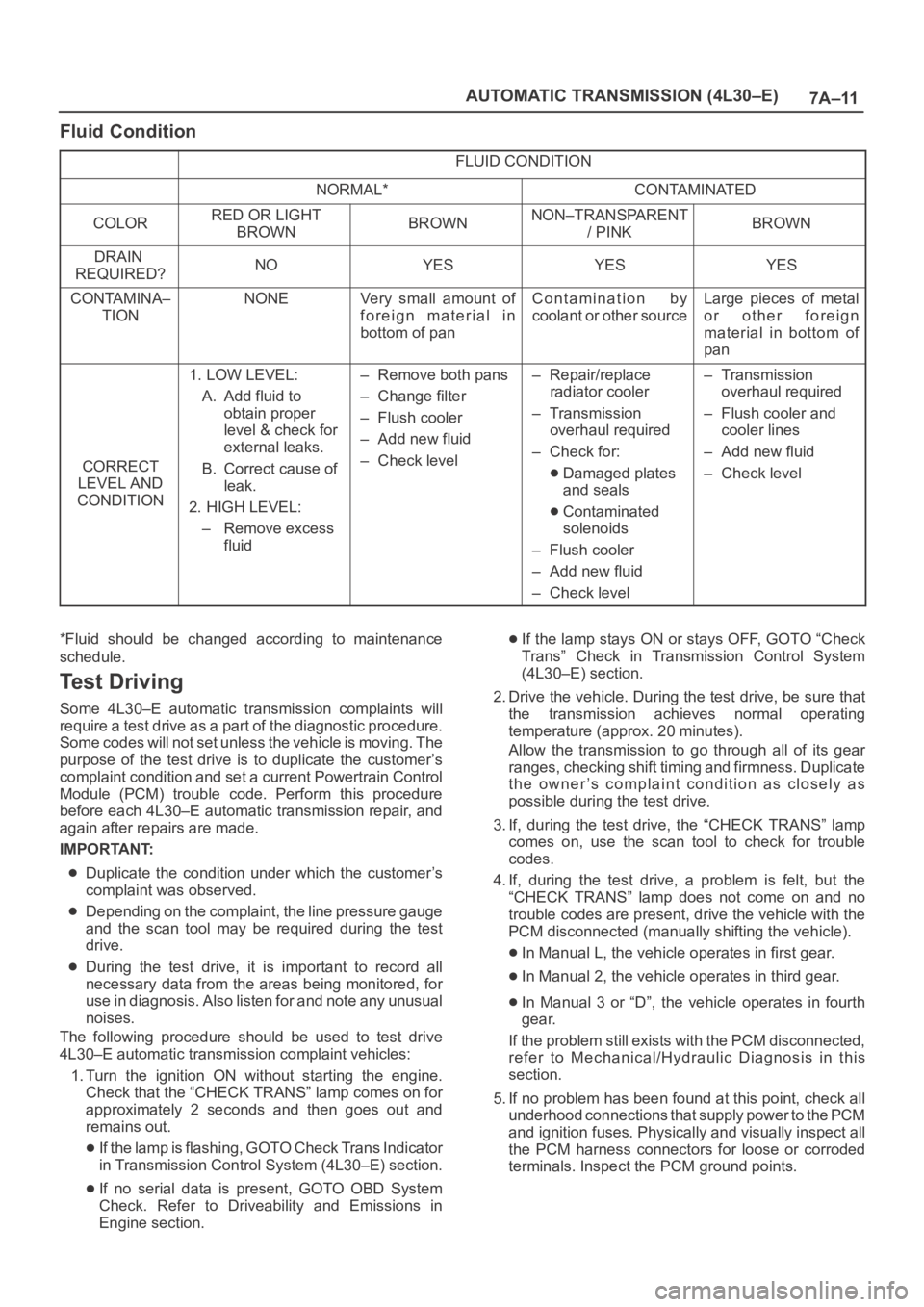
Fluid Condition
FLUID CONDITION
NORMAL*CONTAMINATED
COLORRED OR LIGHT
BROWNBROWNNON–TRANSPARENT
/ PINKBROWN
DRAIN
REQUIRED?NOYESYESYES
CONTAMINA–
TIONNONEVery small amount of
foreign material in
bottom of panContamination by
coolant or other sourceLarge pieces of metal
or other foreign
material in bottom of
pan
CORRECT
LEVEL AND
CONDITION
1. LOW LEVEL:
A. Add fluid to
obtain proper
level & check for
external leaks.
B. Correct cause of
leak.
2. HIGH LEVEL:
– Remove excess
fluid– Remove both pans
– Change filter
– Flush cooler
– Add new fluid
– Check level– Repair/replace
radiator cooler
–Transmission
overhaul required
– Check for:
Damaged plates
and seals
Contaminated
solenoids
– Flush cooler
– Add new fluid
– Check level
–Transmission
overhaul required
– Flush cooler and
cooler lines
– Add new fluid
– Check level
*Fluid should be changed according to maintenance
schedule.
Te s t D r i v i n g
Some 4L30–E automatic transmission complaints will
require a test drive as a part of the diagnostic procedure.
Some codes will not set unless the vehicle is moving. The
purpose of the test drive is to duplicate the customer’s
complaint condition and set a current Powertrain Control
Module (PCM) trouble code. Perform this procedure
before each 4L30–E automatic transmission repair, and
again after repairs are made.
IMPORTANT:
Duplicate the condition under which the customer’s
complaint was observed.
Depending on the complaint, the line pressure gauge
and the scan tool may be required during the test
drive.
During the test drive, it is important to record all
necessary data from the areas being monitored, for
use in diagnosis. Also listen for and note any unusual
noises.
The following procedure should be used to test drive
4L30–E automatic transmission complaint vehicles:
1. Turn the ignition ON without starting the engine.
Check that the “CHECK TRANS” lamp comes on for
approximately 2 seconds and then goes out and
remains out.
If the lamp is flashing, GOTO Check Trans Indicator
in Transmission Control System (4L30–E) section.
If no serial data is present, GOTO OBD System
Check. Refer to Driveability and Emissions in
Engine section.
If the lamp stays ON or stays OFF, GOTO “Check
Trans” Check in Transmission Control System
(4L30–E) section.
2. Drive the vehicle. During the test drive, be sure that
the transmission achieves normal operating
temperature (approx. 20 minutes).
Allow the transmission to go through all of its gear
ranges, checking shift timing and firmness. Duplicate
the owner’s complaint condition as closely as
possible during the test drive.
3. If, during the test drive, the “CHECK TRANS” lamp
comes on, use the scan tool to check for trouble
codes.
4. If, during the test drive, a problem is felt, but the
“CHECK TRANS” lamp does not come on and no
trouble codes are present, drive the vehicle with the
PCM disconnected (manually shifting the vehicle).
In Manual L, the vehicle operates in first gear.
In Manual 2, the vehicle operates in third gear.
In Manual 3 or “D”, the vehicle operates in fourth
gear.
If the problem still exists with the PCM disconnected,
refer to Mechanical/Hydraulic Diagnosis in this
section.
5. If no problem has been found at this point, check all
underhood connections that supply power to the PCM
and ignition fuses. Physically and visually inspect all
the PCM harness connectors for loose or corroded
terminals. Inspect the PCM ground points.
Page 5719 of 6000
7A–30
AUTOMATIC TRANSMISSION (4L30–E)
Removal
1. Disconnect battery ground cable.
2. Remove transfer control lever knob.
3. Remove front console.
Disconnect wiring harness connectors from front
console.
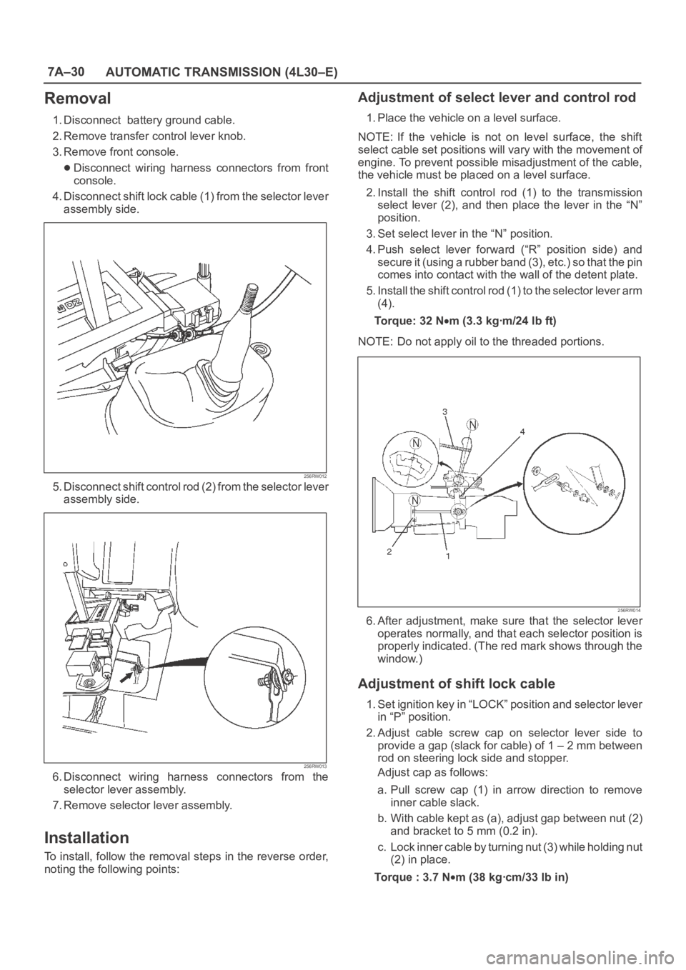
4. Disconnect shift lock cable (1) from the selector lever
assembly side.
256RW012
5. Disconnect shift control rod (2) from the selector lever
assembly side.
256RW013
6. Disconnect wiring harness connectors from the
selector lever assembly.
7. Remove selector lever assembly.
Installation
To install, follow the removal steps in the reverse order,
noting the following points:
Adjustment of select lever and control rod
1. Place the vehicle on a level surface.
NOTE: If the vehicle is not on level surface, the shift
select cable set positions will vary with the movement of
engine. To prevent possible misadjustment of the cable,
the vehicle must be placed on a level surface.
2. Install the shift control rod (1) to the transmission
select lever (2), and then place the lever in the “N”
position.
3. Set select lever in the “N” position.
4. Push select lever forward (“R” position side) and
s e c u r e i t ( u s i n g a r u b b e r b a n d ( 3 ) , e t c . ) s o t h a t t h e p i n
comes into contact with the wall of the detent plate.
5. Install the shift control rod (1) to the selector lever arm
(4).
To r q u e : 3 2 N
m (3.3 kgꞏm/24 lb ft)
NOTE: Do not apply oil to the threaded portions.
256RW014
6. After adjustment, make sure that the selector lever
operates normally, and that each selector position is
properly indicated. (The red mark shows through the
window.)
Adjustment of shift lock cable
1. Set ignition key in “LOCK” position and selector lever
in “P” position.
2. Adjust cable screw cap on selector lever side to
provide a gap (slack for cable) of 1 – 2 mm between
rod on steering lock side and stopper.
Adjust cap as follows:
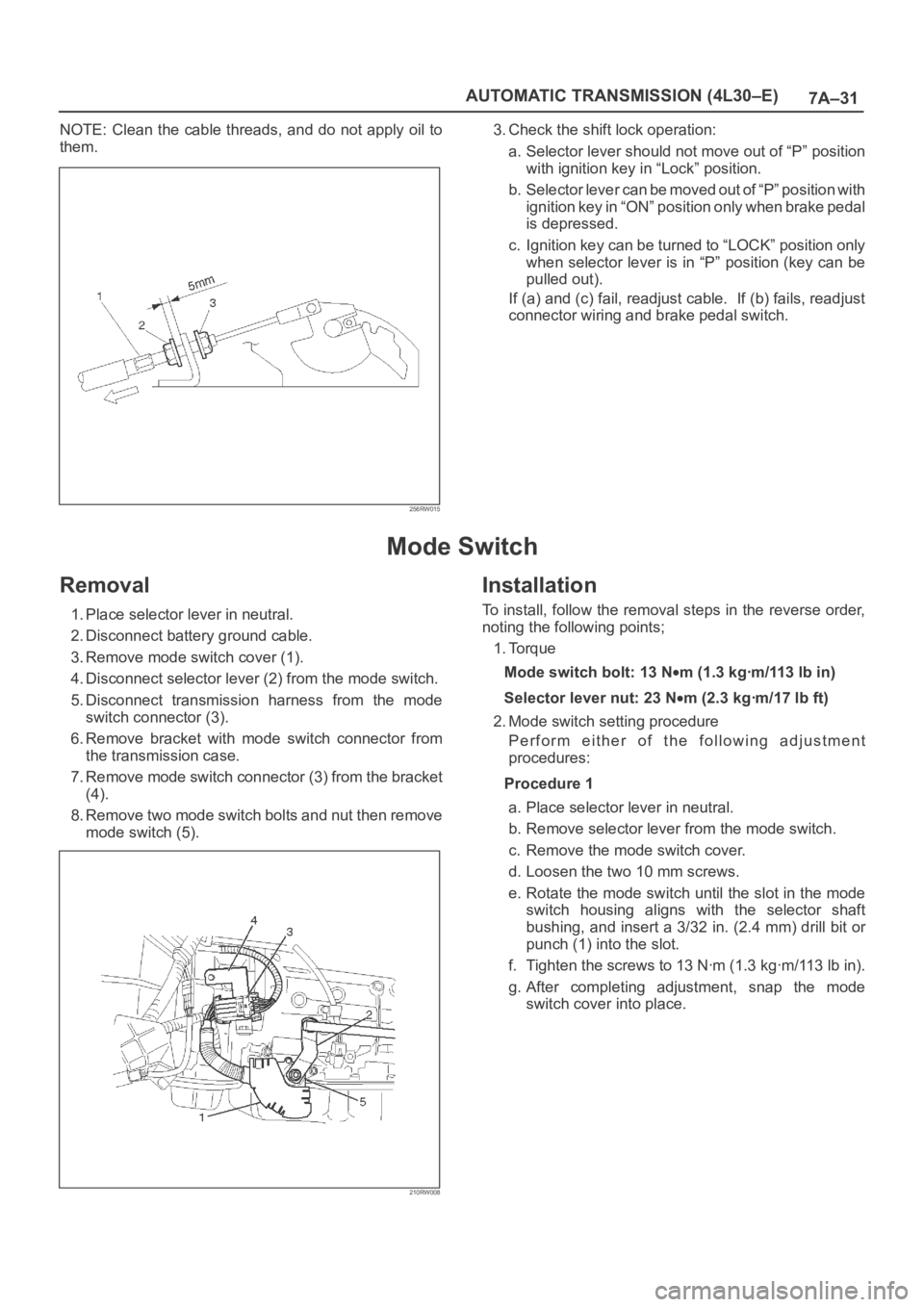
a. Pull screw cap (1) in arrow direction to remove
inner cable slack.
b. With cable kept as (a), adjust gap between nut (2)
and bracket to 5 mm (0.2 in).
c. Lock inner cable by turning nut (3) while holding nut
(2) in place.
Torque : 3.7 N
m (38 kgꞏcm/33 lb in)
Page 5720 of 6000
7A–31 AUTOMATIC TRANSMISSION (4L30–E)
NOTE: Clean the cable threads, and do not apply oil to
them.
256RW015
3. Check the shift lock operation:
a. Selector lever should not move out of “P” position
with ignition key in “Lock” position.
b. Selector lever can be moved out of “P” position with
ignition key in “ON” position only when brake pedal
is depressed.
c. Ignition key can be turned to “LOCK” position only
when selector lever is in “P” position (key can be
pulled out).
If (a) and (c) fail, readjust cable. If (b) fails, readjust
connector wiring and brake pedal switch.
Mode Switch
Removal
1. Place selector lever in neutral.
2. Disconnect battery ground cable.
3. Remove mode switch cover (1).
4. Disconnect selector lever (2) from the mode switch.
5. Disconnect transmission harness from the mode
switch connector (3).
6. Remove bracket with mode switch connector from
the transmission case.
7. Remove mode switch connector (3) from the bracket
(4).
8. Remove two mode switch bolts and nut then remove
mode switch (5).
210RW008
Installation
To install, follow the removal steps in the reverse order,
noting the following points;
1. Torque
Mode switch bolt: 13 N
m(1.3kgꞏm/113lbin)
Selector lever nut: 23 N
m (2.3 kgꞏm/17 lb ft)
2. Mode switch setting procedure
Perform either of the following adjustment
procedures:
Procedure 1
a. Place selector lever in neutral.
b. Remove selector lever from the mode switch.
c. Remove the mode switch cover.
d. Loosen the two 10 mm screws.
e. Rotate the mode switch until the slot in the mode
switch housing aligns with the selector shaft
bushing, and insert a 3/32 in. (2.4 mm) drill bit or
punch (1) into the slot.
f. Tighten the screws to 13 Nꞏm (1.3 kgꞏm/113 lb in).
g. After completing adjustment, snap the mode
switch cover into place.
Page 5789 of 6000

7A–8 AUTOMATIC TRANSMISSION (AW30-40LE)
Winter mode control • The TCM controls the vehicle start smoothly on low frictional road like
snow road by executing this control.
Activate condition:
1. Excluding "2", "L" range
2. Vehicle speed is less than 11 km/h
3. Transmission oil temperature is less than 115
C
4. Throttle opening is less than 8%
5. Excluding winter mode
Cancel condition:
1. When winter mode switch is pushed again
2. When either "2" or "L" is detected
3. Ignition switch "OFF"
4. Vehicle speed is more than 34 km/h for 1 second or mode continuously
5. Transmission oil temperature is more than 130
C
Fail-safe function • When trouble occurs to vehicle sensor and each solenoid, TCM
automatically exer ts fail-safe control not to spoil driveability.
• This control is exer ted when sensor or actuator is in trouble, while TCM
works normally.
Diagnosis function • If there is an abnormality in vehicle sensors, each solenoid (S1-S3, STH),
or throttle position sensor, "CHECK TRANS" lamp is actuated to warn the
drive. But when the abnormality items have been restored to normal, the
light does not blink.
• Faulty parts are memorized in TCM. If self-diagnosis star t signal is
inputted, "CHECK TRANS" lamp is blinked and results of diagnosis are
indicated. A history of faults remains recorded even when IGN switch is off.
TECH 2 • Output of control data in the TCM
• Actuator (Solenoid) operation check
• Erasure of trouble code
Page 5795 of 6000
7A–14 AUTOMATIC TRANSMISSION (AW30-40LE)
821RY00012
F07LV002
740RY00013
740RY00014
SELF-DIAGNOSIS
Warning to the driver
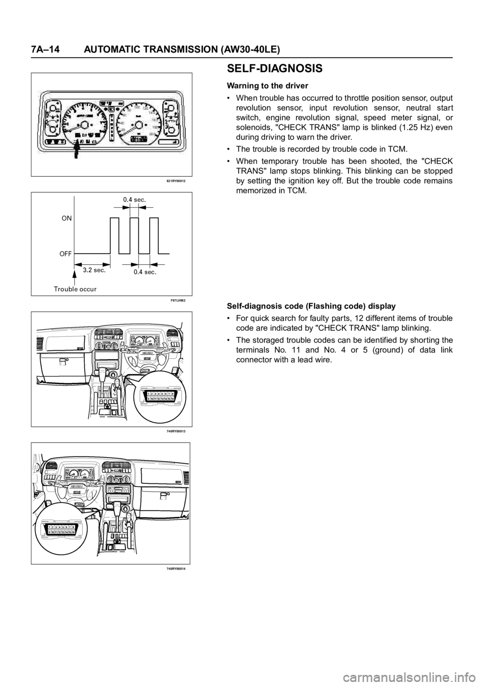
• When trouble has occurred to throttle position sensor, output
revolution sensor, input revolution sensor, neutral star t
switch, engine revolution signal, speed meter signal, or
solenoids, "CHECK TRANS" lamp is blinked (1.25 Hz) even
during driving to warn the driver.
• The trouble is recorded by trouble code in TCM.
• When temporary trouble has been shooted, the "CHECK
TRANS" lamp stops blinking. This blinking can be stopped
by setting the ignition key off. But the trouble code remains
memorized in TCM.
Self-diagnosis code (Flashing code) display
• For quick search for faulty parts, 12 different items of trouble
code are indicated by "CHECK TRANS" lamp blinking.
• The storaged trouble codes can be identified by shor ting the
terminals No. 11 and No. 4 or 5 (ground) of data link
connector with a lead wire.
Page 5796 of 6000
AUTOMATIC TRANSMISSION (AW30-40LE) 7A–15
F07LV001
Indication Method:
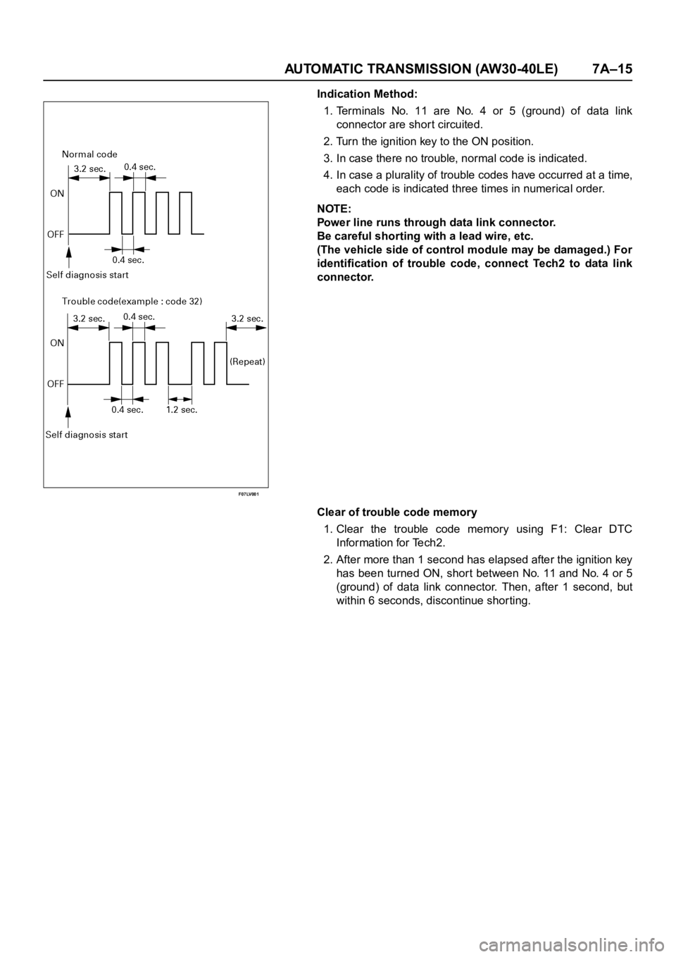
1.Terminals No. 11 are No. 4 or 5 (ground) of data link
connector are short circuited.
2. Turn the ignition key to the ON position.
3. In case there no trouble, normal code is indicated.
4. In case a plurality of trouble codes have occurred at a time,
each code is indicated three times in numerical order.
NOTE:
Power line runs through data link connector.
Be careful shorting with a lead wire, etc.
(The vehicle side of control module may be damaged.) For
identification of trouble code, connect Tech2 to data link
connector.
Clear of trouble code memory
1. Clear the trouble code memory using F1: Clear DTC
Information for Tech2.
2. After more than 1 second has elapsed after the ignition key
has been turned ON, short between No. 11 and No. 4 or 5
(ground) of data link connector. Then, after 1 second, but
within 6 seconds, discontinue shorting.