Page 3205 of 6000
8F–10BODY STRUCTURE
Parts Location (W/Rear Combination Light and License Light)
690RW010
Legend
(1) Back Bar
(2) Rear Combination Light Back Plate
(3) Rear Bumper Retainer
(4) Reinforce Assembly
(5) Rear Bumper Slider Brackets
(6) Rear Combination Light Assembly
(7) License Light
(8) Reinforce Lower Screws(9) Reinforce Upper Bolts
(10) Rear Step
(11) Rear Step Clips
(12) Rear Bumper Fascia Bracket Screws
(13) Rear Bumper Assembly
(14) Rear Bumper Side Covers
(15) Rear Bumper Fascia Brackets
(16) Mud Flaps
(17) Rear Bumper Assembly Fixing Bolts
Removal
1. Disconnect battery ground cable.
2. Remove rear bumper side covers.3. Remove mud flaps.Remove three screws.
4. Remove rear bumper fascia bracket screws.
Page 3207 of 6000
8F–12BODY STRUCTURE
Parts Location (W/Rear Combination Light)
690RW012
Legend
(1) Back Bar
(2) Rear Combination Light Back Plate
(3) Rear Bumper Retainer
(4) Reinforce Assembly
(5) Rear Bumper Slider Brackets
(6) Rear Combination Light Assembly
(7) Rear Step Clips
(8) Reinforce Upper Bolts(9) Reinforce Lower Screws
(10) Rear Bumper Fascia Bracket Screws
(11) Rear Bumper Assembly
(12) Rear Bumper Side Covers
(13) Rear Bumper Fascia Brackets
(14) Mud Flaps
(15) Clips
(16) Rear Bumper Assembly Fixing Bolts
Removal
1. Disconnect battery ground cable.
2. Remove rear bumper side covers.3. Remove mud flaps.Remove three screws.
4. Remove rear bumper fascia bracket screws.
Page 3217 of 6000
8F–22BODY STRUCTURE
Front Fender Panel
Parts Location
605RW008
Legend
(1) Cowl Cover
(2) Front Mud Flap
(3) Antenna Bezel(4) Side Flasher Light
(5) Front Fender Panel
(6) Front Combination Lamp Assembly
(7) Inner Liner
Removal
1. Open the hood.
2. Support the hood.
3. Disconnect the battery ground cable.
4. Remove cowl cover.
Refer to Cowl Cover in this section.
5. Remove front combination lamp assembly.
Disconnect fixing screw and connector.6. Remove front mud flap.
Disconnect three fixing screws and four clips.
7. Remove inner liner.
8. Remove antenna bezel.
Refer to Entertainment in this section.
9. Remove side flasher light.
Refer to Lighting System in this section.
Page 3249 of 6000

8F–54BODY STRUCTURE
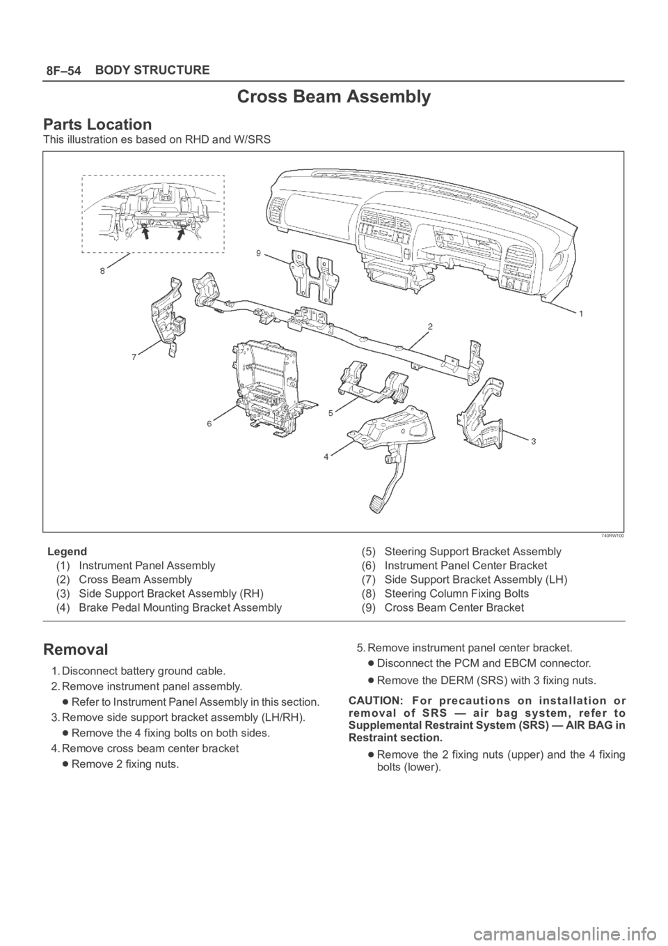
Cross Beam Assembly
Parts Location
This illustration es based on RHD and W/SRS
740RW100
Legend
(1) Instrument Panel Assembly
(2) Cross Beam Assembly
(3) Side Support Bracket Assembly (RH)
(4) Brake Pedal Mounting Bracket Assembly(5) Steering Support Bracket Assembly
(6) Instrument Panel Center Bracket
(7) Side Support Bracket Assembly (LH)
(8) Steering Column Fixing Bolts
(9) Cross Beam Center Bracket
Removal
1. Disconnect battery ground cable.
2. Remove instrument panel assembly.
Refer to Instrument Panel Assembly in this section.
3. Remove side support bracket assembly (LH/RH).
Remove the 4 fixing bolts on both sides.
4. Remove cross beam center bracket
Remove 2 fixing nuts.5. Remove instrument panel center bracket.
Disconnect the PCM and EBCM connector.
Remove the DERM (SRS) with 3 fixing nuts.
CAUTION: For precautions on installation or
removal of SRS — air bag system, refer to
Supplemental Restraint System (SRS) — AIR BAG in
Restraint section.
Remove the 2 fixing nuts (upper) and the 4 fixing
bolts (lower).
Page 3251 of 6000
8F–56BODY STRUCTURE
Front Door Assembly
Parts Location
630RS001
Legend
(1) Door Check Arm Pin
(2) Front Door Assembly(3) Door Hinge Assembly
(4) Hinge Bolt
(5) Door Harness Connection
Removal
1. Disconnect the battery ground cable.
2. Remove door check arm pin (1).
630RS002
3. Remove hinge bolt.
Align the hinge bolt to the door side hinge and put a
marker on it.
4. Remove door harness connection (2).
Pull the door harness grommet out in order to
disconnect the harness connection.
810RS001
5. Remove front door assembly.
Installation
To install, follow the removal steps in the reverse order,
noting the following points:
1. Align the door fitting to the body by referring to Body
Dimensions in this section.
2. Tighten the door hinge bolts to the specified torque.
Torque : 34 N
m (3.5kgꞏm/25 lb ft)
3. Apply chassis grease to the door check arm pin and
the door hinge moving surface.
Page 3252 of 6000
8F–57 BODY STRUCTURE
Rear Door Assembly
Parts Location
650RW007
Legend
(1) Door Check Arm Pin
(2) Door Harness Connection(3) Rear Door Assembly
(4) Hinge Bolt
Removal
1. Disconnect the battery ground cable.
2. Apply a setting mark on the body side hinge.
3. Remove door check arm pin (1).
630RS002
4. Remove hinge bolt.
Open the front door and remove the body side hinge
bolts (2).
650RS002
Page 3254 of 6000
8F–59 BODY STRUCTURE
Door Check Arm Assembly (Front & Rear)
Parts Location
630RS003
Legend
(1) Front or Rear Door
(2) Door Trim Panel
(3) Check Arm Assembly(4) Check Arm Pin Bracket
(5) Check Arm Pin
(6) Front or Center Pillar
Removal
1. Disconnect the battery ground cable.
2. Remove door trim panel.
Refer to Exterior / Interrior Trim in this section.
3. Remove check arm pin (1).
630RS002
Page 3255 of 6000
8F–60BODY STRUCTURE
4. Remove check arm assembly.
Carefully peel off the water proof sheet as much as
necessary, for check arm removal.
Installation
To install, follow the removal steps in the reverse order,
noting the following point.1. When installing the check arm assembly, note its
marking to ensure using the appropriate part.
2. Tighten the check arm fixing nuts to the specified
torque.
Torque : 13 N
m (1.3kgꞏm/113 lb in)
3. Apply chassis grease to the check arm pin moving
surface.
Front Window Regulator, Glass And Glass Run
Parts Location
631RS002
Legend
(1) Speaker Box
(2) Glass Run
(3) Glass
(4) Rear Guide Rail(5) Window Regulator
(6) Window Regulator with Power Window
(7) Window Regulator Motor Connector
(8) Door Trim Panel
(9) Waterproof Sheet
Removal
1. Disconnect the battery ground cable.
2. Remove door trim panel.
Refer to Exterior / Interrior Trim in this section.
3. Remove speaker box.